Download to read offline

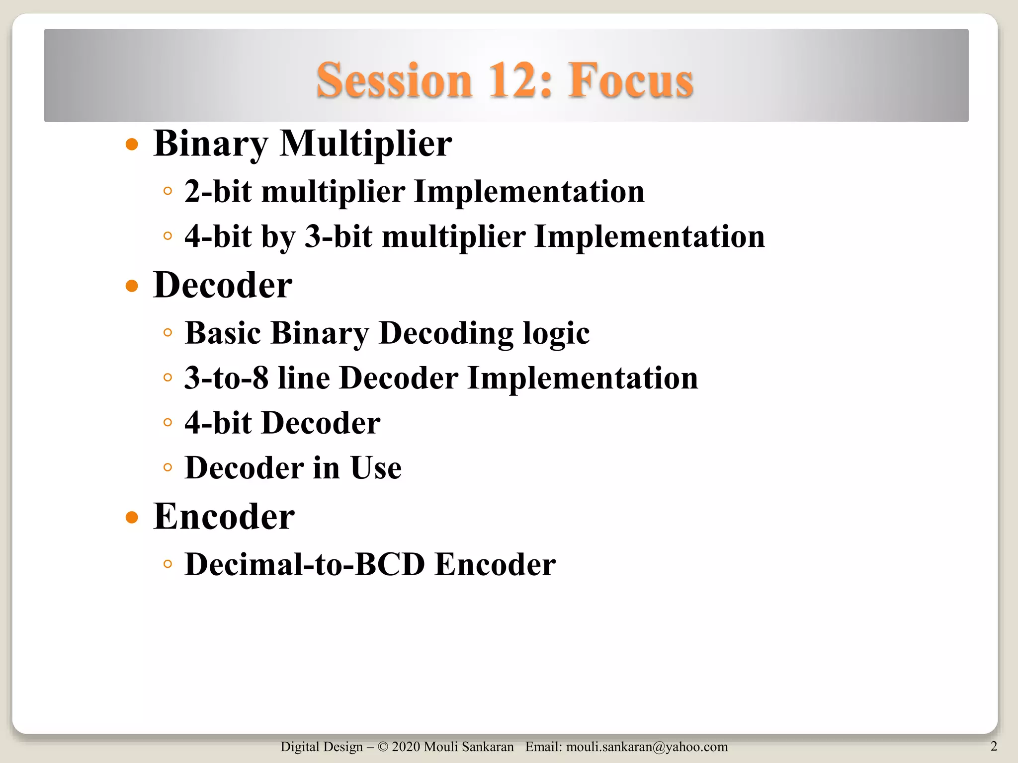

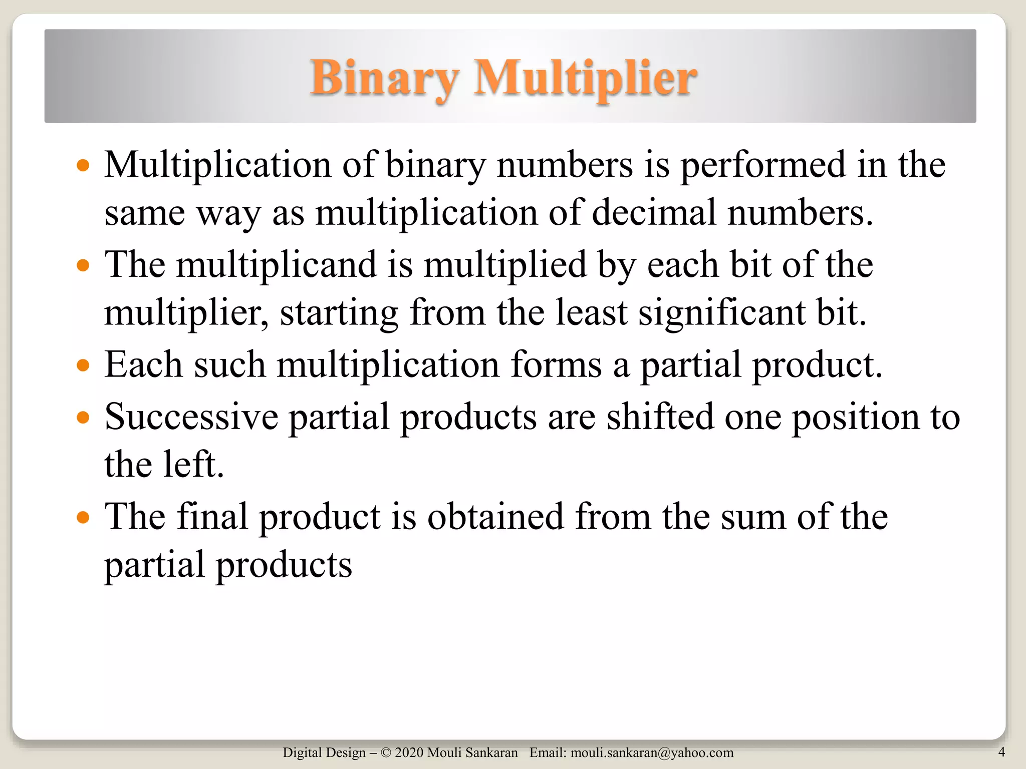

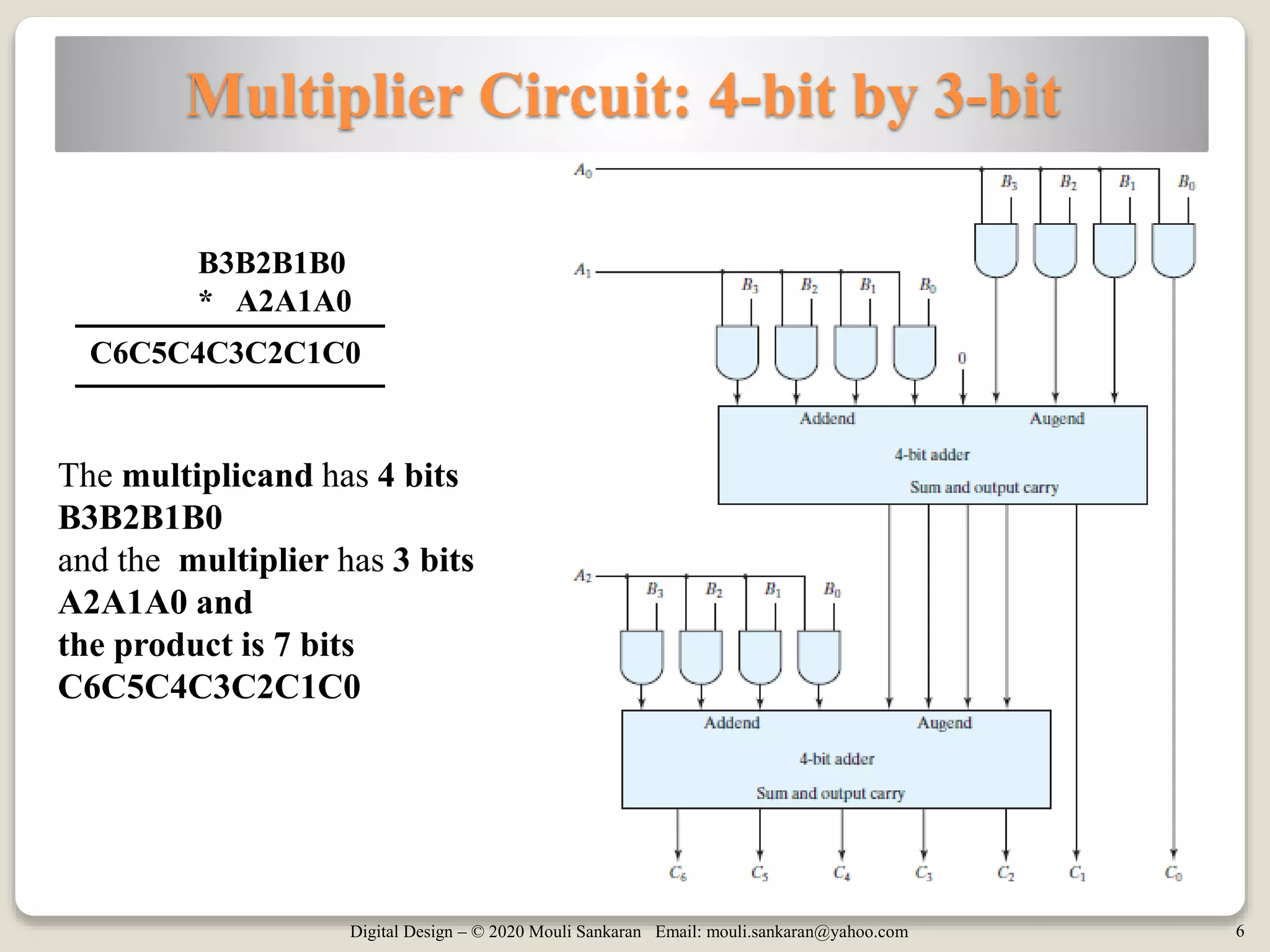

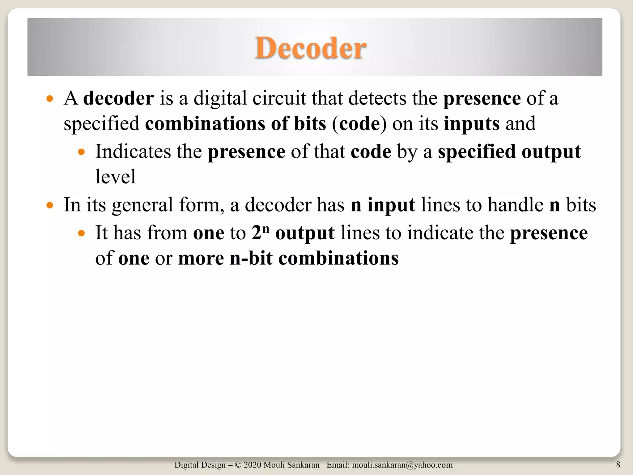

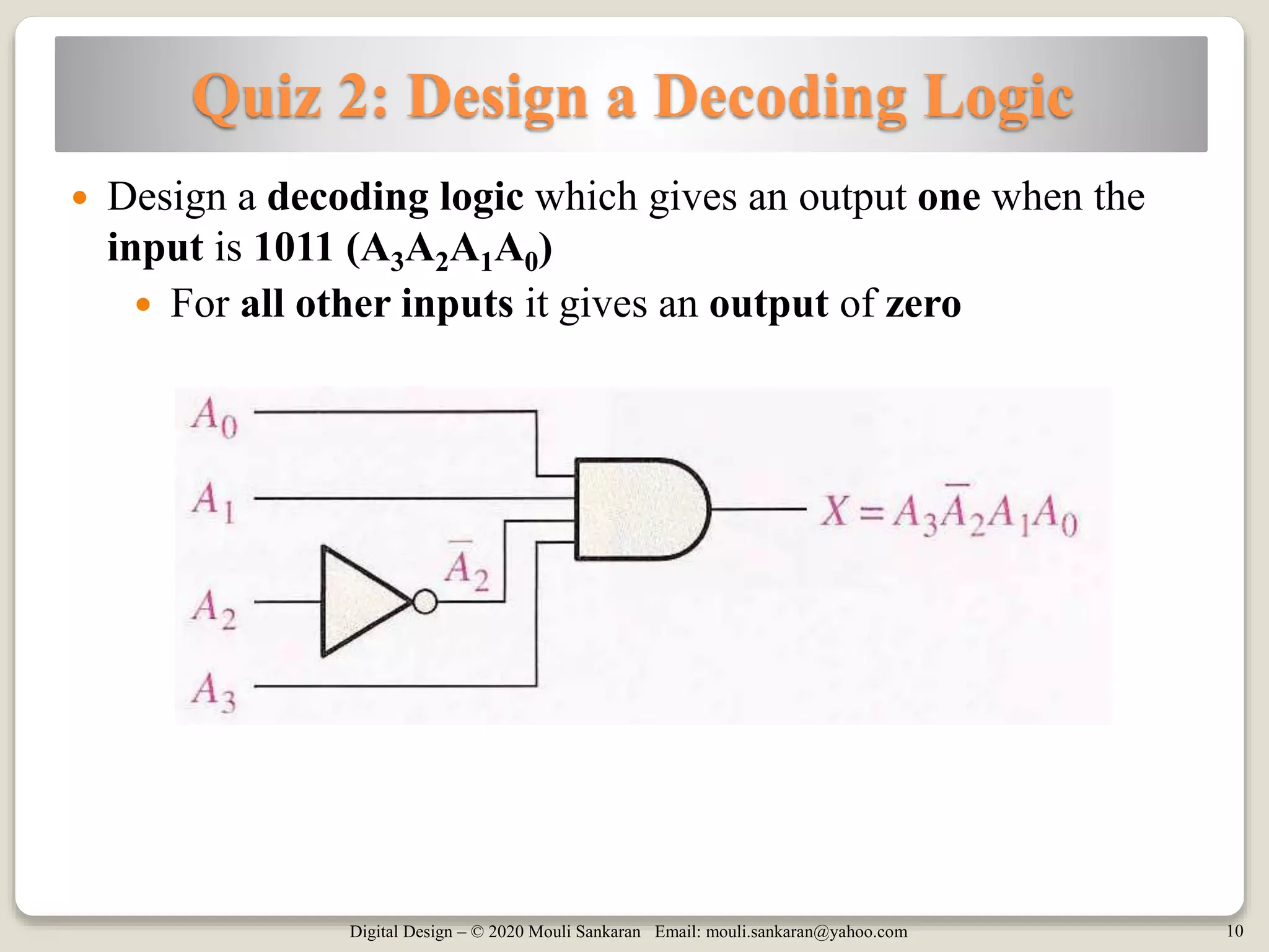
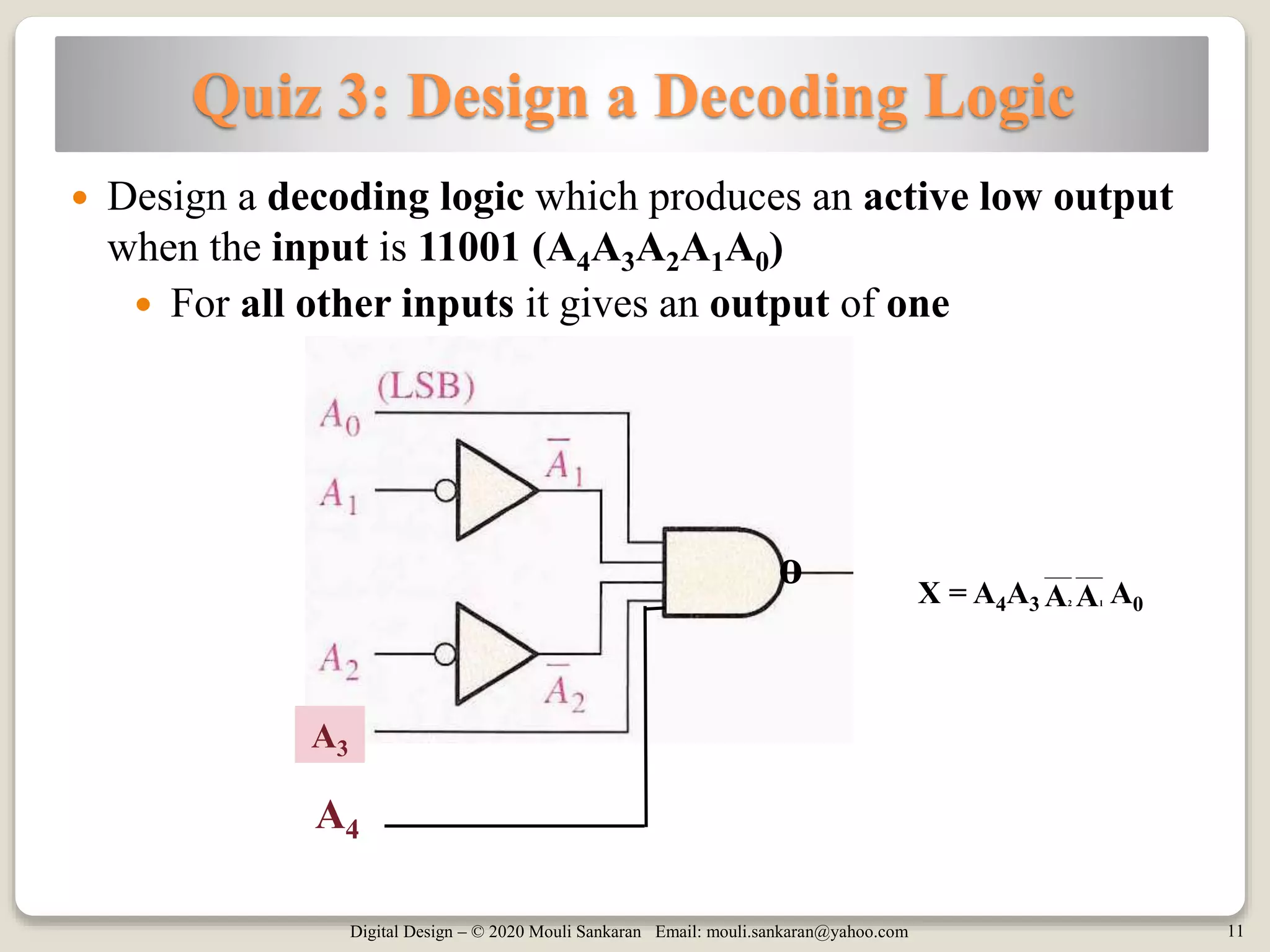
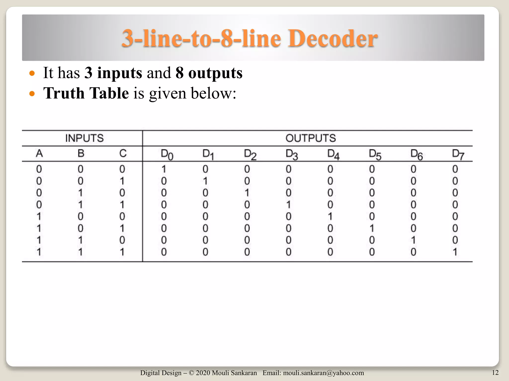

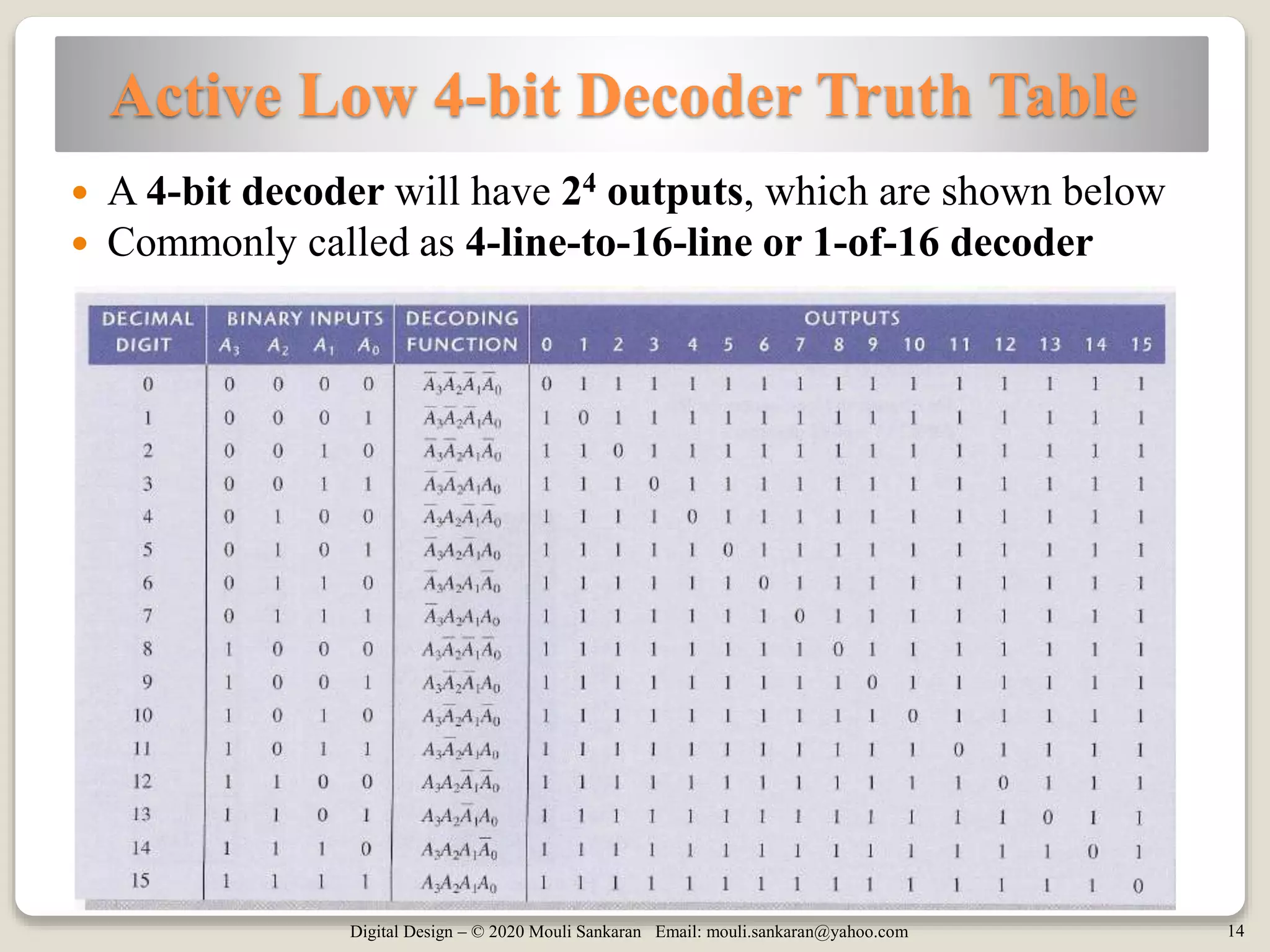


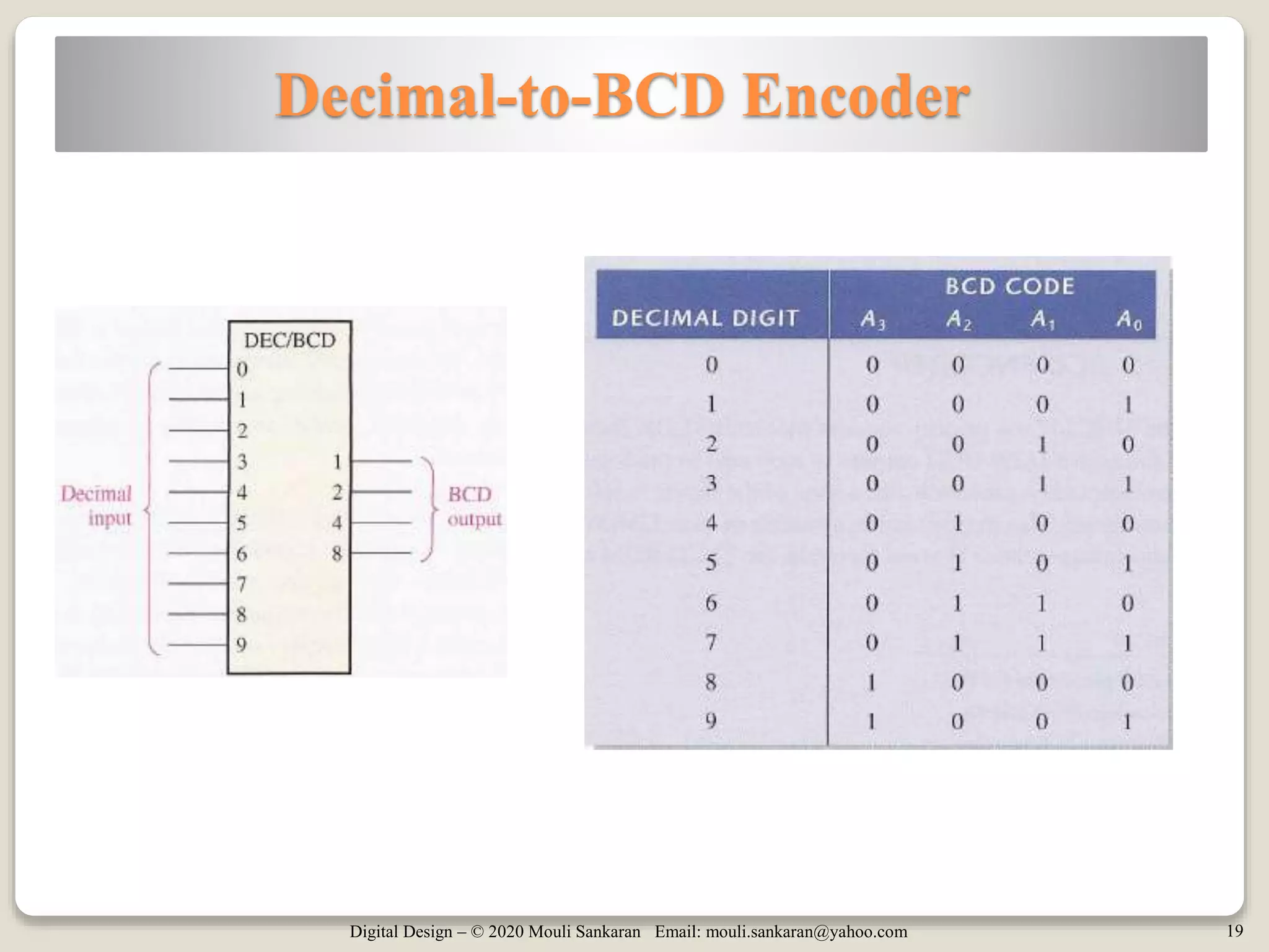


The document covers digital design concepts including binary multipliers, decoders, and encoders. It explains how binary multiplication is performed, presents implementations for 2-bit and 4-bit by 3-bit multipliers, and details the functions of decoders and encoders with relevant designs. Additionally, it includes quizzes on decoding logic and references related to the content.


![Analysis_Design_Procedures_with_Diagrams[1].pptx](https://cdn.slidesharecdn.com/ss_thumbnails/analysisdesignprocedureswithdiagrams1-250902110500-deeb2e09-thumbnail.jpg?width=640&height=640&fit=bounds)
![Analysis_Design_Procedures_with_Diagrams[1].pptx](https://cdn.slidesharecdn.com/ss_thumbnails/analysisdesignprocedureswithdiagrams1-250902110906-778fd956-thumbnail.jpg?width=640&height=640&fit=bounds)