Downloaded 167 times


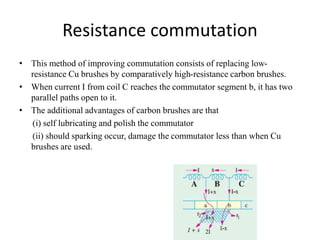
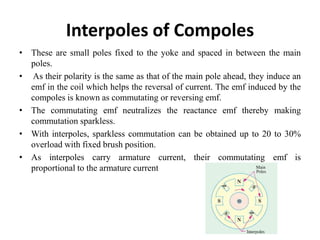
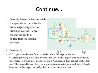


This document discusses armature reaction in DC machines and methods to minimize it. It describes how armature reaction demagnetizes and distorts the main magnetic flux, weakening it in some areas and strengthening it in others. Compensating windings and interpoles are introduced to counteract the cross-magnetizing effect. Commutation, the process of reversing current in armature coils, is also covered. Resistance commutation using carbon brushes and emf commutation using interpoles are two methods discussed to improve commutation and reduce sparking. Interpoles produce a reversing emf that neutralizes reactance voltage during commutation for smooth current reversal.


![Amit seth armature_reaction[1]](https://cdn.slidesharecdn.com/ss_thumbnails/amitsetharmaturereaction1-151213065631-thumbnail.jpg?width=640&height=640&fit=bounds)