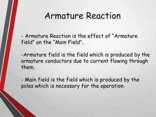
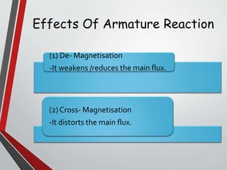
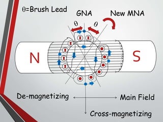
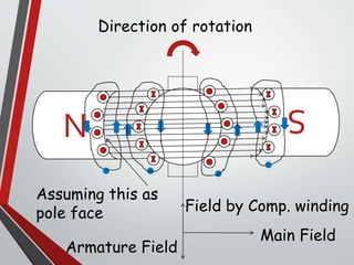
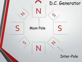
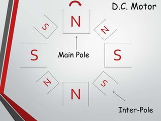
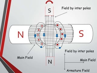
Gujarat Power Engineering
& Research Institute
By-
-Karan Thawani(58)
Contents:-
- Armature Reaction
-Compensating winding
- Interpoles
Armature Reaction
- Armature Reaction is the effect of “Armature
field” on the “Main Field”.
-Armature field is the field which is produced by the
armature conductors due to current flowing through
them.
- Main field is the field which is produced by the
poles which is necessary for the operation.
(1) De- Magnetisation
-It weakens /reduces the main flux.
(2) Cross- Magnetisation
-It distorts the main flux.
Effects Of Armature Reaction
Terminology Related To
Armature Reaction
-MNA(Magnetically Neutral Axis)
It is the axis along which no E.M.F is produced, hence
brushes are kept on this axis.
-GNA(Geometrically Neutral Axis)
It is the axis which divides the armature core in two
equal parts.
-Polar Axis
It is the imaginary line which joins the
center of NS poles.
o Consider a two pole D.C Generator.
o For the sake of simplicity, the brushes are shown
directly touching the armature conductors, but
practically they touch commutator segments.
o Assume that there is no current flowing through
armature conductors, Hence..
(1) The flux is distributed symmetrically with respect
to polar axis.
(2) The M.N.A coincides the G.NA.
N
S
Pole
Armature
Brush
Main Field
Armature conductors
MNA/GNA
o Now assume that there is current flowing through
the armature conductors and the direction of rotation
is clock-wise.
o According to Fleming’s right hand rule, the direction
of current is inwards in conductors which are influence
of N pole and outwards which are influence of S pole.
o Inward flow of current is represented by “ ”
whereas the outward flow is represented
by “ ” .
o Now due to the current flowing through the armature
conductors, magnetic flux is produced around the
armature conductors.
o According to Fleming’s right hand rule, the direction
of this flux is clock-wise in conductors which are
influence of N pole and Anti-clock wise in conductors
which are influence of s pole.
o Now, the main flux is no more longer symmetrical
about the pole axis.
o Hence the main field is distorted.
o Now, the resultant flux is the vector sum of the main
field and the armature field.
o Hence the position of M.N.A changes(which is always
perpendicular to the resultant flux).
o Due to change in position of M.N.A, the position of
brush also changes which in known as “Brush Lead”.
o Brush lead is in the direction of rotation in the case
of D.C. Generator, while in the opposite direction of
rotation in case of D.C. Motor.
N
S
Direction of rotation
Current going inside
Current coming outside
Main Field
Armature Field
o Now due to brush shift, the armature conductors and
hence armature current is redistributed.
o Some armature conductors which were earlier under
the influence of N-pole come under the influence of S-
pole and vice-versa.
o According to Fleming’s right hand thumb rule,
armature conductors in 2(where = brush lead)
produces De-magnetizing effect and remaining
produces cross-magnetizing effect.
N
S
Main FieldDe-magnetizing
Cross-magnetizing
New MNAGNA
=Brush Lead
o Magnetic flux density increases over one half of the
core and decreases over the other half.
o The flux wave is distorted and there is a shift in the
position of M.N.A.
o It causes the commutation problem.
Effects Of Armature
Reaction
Compensating winding
o Compensating windings are used to nullify the cross-
magnetizing effect.
o These windings are kept in slots of pole faces.
o It carries current in opposite direction to the
current of armature winding just below the pole faces.
o It is connected in series with the armature winding.
N
S
Direction of rotation
Assuming this as
pole face
Main Field
Armature Field
Field by Comp. winding
Drawbacks:
o There is only one disadvantage of compensating
winding and that is it is costly.
Advantages:
o It is used in large machines heaving heavy
fluctuation.
o It is used when same output is required at low
voltage.
o As the compensating windings are too costly, inter-
poles are used to neutralize the Cross-magnetizing
effect of armature reaction.
o These are small poles fixed to the yoke and spaced in
between the main poles.
o They are wound with comparatively few heavy gauge
copper wire turns and are connected in series with the
armature so that they carry full armature current.
o Their polarity is same as the “Leading pole” in the case
of D.C. Generator and “Trailing pole” in d case of D.C.
Motor considering the direction of rotation.
Inter-poles:
N
N
S S
D.C. Generator
Main Pole
Inter-Pole
N
N
S S
D.C. Motor
Main Pole
Inter-Pole
N
S
N
S
Main Field
Field by inter poles
Armature Field
Main Field
Field by inter poles
o There are mainly two functions of inter-poles:-
1. As their polarity is the same as that of the leading
pole, they induce an e.m.f in the coil(under
commutation) which helps the reversal of current.
The e.m.f induced by the inter-poles is known as
reversing-commutating e.m.f. This e.m.f neutralizes
the reactance e.m.f and makes commutation
sparkless.
2. Another function of the inter-poles is to neutralize
the cross-magnetizing effect of armature reaction.
Hence, brushes are not be shifted from the original
position.
Armature reaction

Armature reaction

  • 1.
    Gujarat Power Engineering &Research Institute By- -Karan Thawani(58) Contents:- - Armature Reaction -Compensating winding - Interpoles
  • 2.
    Armature Reaction - ArmatureReaction is the effect of “Armature field” on the “Main Field”. -Armature field is the field which is produced by the armature conductors due to current flowing through them. - Main field is the field which is produced by the poles which is necessary for the operation.
  • 3.
    (1) De- Magnetisation -Itweakens /reduces the main flux. (2) Cross- Magnetisation -It distorts the main flux. Effects Of Armature Reaction
  • 4.
    Terminology Related To ArmatureReaction -MNA(Magnetically Neutral Axis) It is the axis along which no E.M.F is produced, hence brushes are kept on this axis. -GNA(Geometrically Neutral Axis) It is the axis which divides the armature core in two equal parts. -Polar Axis It is the imaginary line which joins the center of NS poles.
  • 5.
    o Consider atwo pole D.C Generator. o For the sake of simplicity, the brushes are shown directly touching the armature conductors, but practically they touch commutator segments. o Assume that there is no current flowing through armature conductors, Hence.. (1) The flux is distributed symmetrically with respect to polar axis. (2) The M.N.A coincides the G.NA.
  • 6.
  • 7.
    o Now assumethat there is current flowing through the armature conductors and the direction of rotation is clock-wise. o According to Fleming’s right hand rule, the direction of current is inwards in conductors which are influence of N pole and outwards which are influence of S pole. o Inward flow of current is represented by “ ” whereas the outward flow is represented by “ ” .
  • 8.
    o Now dueto the current flowing through the armature conductors, magnetic flux is produced around the armature conductors. o According to Fleming’s right hand rule, the direction of this flux is clock-wise in conductors which are influence of N pole and Anti-clock wise in conductors which are influence of s pole. o Now, the main flux is no more longer symmetrical about the pole axis.
  • 9.
    o Hence themain field is distorted. o Now, the resultant flux is the vector sum of the main field and the armature field. o Hence the position of M.N.A changes(which is always perpendicular to the resultant flux). o Due to change in position of M.N.A, the position of brush also changes which in known as “Brush Lead”. o Brush lead is in the direction of rotation in the case of D.C. Generator, while in the opposite direction of rotation in case of D.C. Motor.
  • 10.
    N S Direction of rotation Currentgoing inside Current coming outside Main Field Armature Field
  • 11.
    o Now dueto brush shift, the armature conductors and hence armature current is redistributed. o Some armature conductors which were earlier under the influence of N-pole come under the influence of S- pole and vice-versa. o According to Fleming’s right hand thumb rule, armature conductors in 2(where = brush lead) produces De-magnetizing effect and remaining produces cross-magnetizing effect.
  • 12.
  • 13.
    o Magnetic fluxdensity increases over one half of the core and decreases over the other half. o The flux wave is distorted and there is a shift in the position of M.N.A. o It causes the commutation problem. Effects Of Armature Reaction
  • 14.
    Compensating winding o Compensatingwindings are used to nullify the cross- magnetizing effect. o These windings are kept in slots of pole faces. o It carries current in opposite direction to the current of armature winding just below the pole faces. o It is connected in series with the armature winding.
  • 15.
    N S Direction of rotation Assumingthis as pole face Main Field Armature Field Field by Comp. winding
  • 16.
    Drawbacks: o There isonly one disadvantage of compensating winding and that is it is costly. Advantages: o It is used in large machines heaving heavy fluctuation. o It is used when same output is required at low voltage.
  • 17.
    o As thecompensating windings are too costly, inter- poles are used to neutralize the Cross-magnetizing effect of armature reaction. o These are small poles fixed to the yoke and spaced in between the main poles. o They are wound with comparatively few heavy gauge copper wire turns and are connected in series with the armature so that they carry full armature current. o Their polarity is same as the “Leading pole” in the case of D.C. Generator and “Trailing pole” in d case of D.C. Motor considering the direction of rotation. Inter-poles:
  • 18.
  • 19.
    N N S S D.C. Motor MainPole Inter-Pole
  • 20.
    N S N S Main Field Field byinter poles Armature Field Main Field Field by inter poles
  • 21.
    o There aremainly two functions of inter-poles:- 1. As their polarity is the same as that of the leading pole, they induce an e.m.f in the coil(under commutation) which helps the reversal of current. The e.m.f induced by the inter-poles is known as reversing-commutating e.m.f. This e.m.f neutralizes the reactance e.m.f and makes commutation sparkless. 2. Another function of the inter-poles is to neutralize the cross-magnetizing effect of armature reaction. Hence, brushes are not be shifted from the original position.