Downloaded 246 times


![References
Indian Railway Year Book 2002-2003
U.S. Army Corps of Engineers, 2000
Transportation Research Board, 2000
• White, Thomas. 2000. Developing The Pacific Northwest Rail Corridor Incremental Plan. [Online]
• 2000. [Cited: September 29, 2011.]
• http://www.halcyon.com/tawhite/Trans/PNWRC%20INCREMENTAL%20PLAN.htm.
• Whitford, R. K. 1981. Railroad Electrification. An Alternative for Petroleum Savings.
Transportation
• Research Record. 1981, 802.
• a planning methodology for railway construction
• cost estimation in north america
• Jeffrey Tyler Von Brown](https://image.slidesharecdn.com/railwayelectrification-151011045726-lva1-app6891/85/Railway-electrification-32-320.jpg)

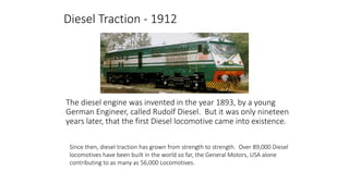
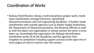
The document discusses the history and development of diesel and electric traction for railways. It provides details on railway electrification in India, including key parts of electrification infrastructure like overhead line equipment, traction substations, and signaling systems. It also describes the cost estimation methodology used by Indian Railways, called the CPM method, which takes into account factors like terrain, land use, speed, track layout and electrification to estimate project costs. Electrification has increased over time in India under successive five-year plans to reduce operating costs and diesel consumption.


