Download as PDF, PPTX

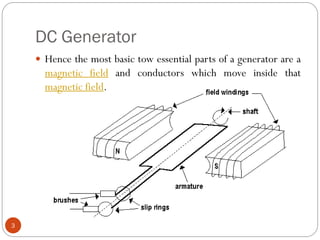
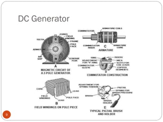
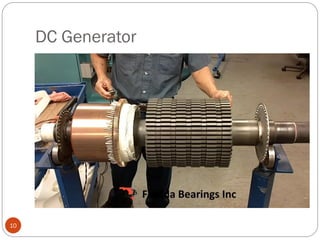
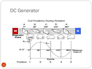
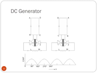


This document discusses DC generators and their components and operation. It describes: 1) The basic components of a DC generator including the armature, electromagnet, slip rings, and brushes. 2) How a DC generator works by inducing an electromotive force (emf) in the armature coils as they cut through the magnetic field. 3) Issues that can occur with commutation in DC generators and different methods to improve commutation such as using resistance or interpole commutation.


