The document discusses direct current (DC) machines and their operation. It provides details on:
1) The basic components and construction of a DC machine including its armature winding, commutator, and field poles.
2) How an alternating current induced in the armature coils is converted to direct current via the commutator and brush assembly.
3) Different types of armature windings including lap and wave windings.
4) Factors that affect the performance of DC machines such as armature reaction and how it can be mitigated through techniques like using interpoles.
5) Equations for calculating the generated electromotive force (EMF) in a DC generator.
Infinite bus bar is one which keeps constant voltage and frequency although the load varies. Thus it may behave like a voltage source with zero internal impedance and infinite rotational inertia.
Infinite bus bar is one which keeps constant voltage and frequency although the load varies. Thus it may behave like a voltage source with zero internal impedance and infinite rotational inertia.
This document contains the Report for a Synchronizing Panel that I made for Diploma main project. It carries the complete detail about parallel operation AC Generators aka Alternators.
This document contains the Report for a Synchronizing Panel that I made for Diploma main project. It carries the complete detail about parallel operation AC Generators aka Alternators.
Construction and components of DC Machine – Principle of operation – Lap and wave windings-EMF equations– circuit model – armature reaction –methods of excitationcommutation – interpoles compensating winding –characteristics of DC generators.
Visualization of magnetic field produced by the field winding excitation with...BhangaleSonal
There are a few ways to detect magnetic fields, one of the most reliable is with magnetic viewer film. This unique film suspends tiny nickel particles over a thin layer of viscous material allowing the particles to align with magnetic fields. It shows the location, as well as how many poles, a magnet has. Magnetic field lines can be drawn by moving a small compass from point to point around a magnet. At each point, draw a short line in the direction of the compass needle. Joining the points together reveals the path of the magnetic field lines.
Sachpazis:Terzaghi Bearing Capacity Estimation in simple terms with Calculati...Dr.Costas Sachpazis
Terzaghi's soil bearing capacity theory, developed by Karl Terzaghi, is a fundamental principle in geotechnical engineering used to determine the bearing capacity of shallow foundations. This theory provides a method to calculate the ultimate bearing capacity of soil, which is the maximum load per unit area that the soil can support without undergoing shear failure. The Calculation HTML Code included.
About
Indigenized remote control interface card suitable for MAFI system CCR equipment. Compatible for IDM8000 CCR. Backplane mounted serial and TCP/Ethernet communication module for CCR remote access. IDM 8000 CCR remote control on serial and TCP protocol.
• Remote control: Parallel or serial interface.
• Compatible with MAFI CCR system.
• Compatible with IDM8000 CCR.
• Compatible with Backplane mount serial communication.
• Compatible with commercial and Defence aviation CCR system.
• Remote control system for accessing CCR and allied system over serial or TCP.
• Indigenized local Support/presence in India.
• Easy in configuration using DIP switches.
Technical Specifications
Indigenized remote control interface card suitable for MAFI system CCR equipment. Compatible for IDM8000 CCR. Backplane mounted serial and TCP/Ethernet communication module for CCR remote access. IDM 8000 CCR remote control on serial and TCP protocol.
Key Features
Indigenized remote control interface card suitable for MAFI system CCR equipment. Compatible for IDM8000 CCR. Backplane mounted serial and TCP/Ethernet communication module for CCR remote access. IDM 8000 CCR remote control on serial and TCP protocol.
• Remote control: Parallel or serial interface
• Compatible with MAFI CCR system
• Copatiable with IDM8000 CCR
• Compatible with Backplane mount serial communication.
• Compatible with commercial and Defence aviation CCR system.
• Remote control system for accessing CCR and allied system over serial or TCP.
• Indigenized local Support/presence in India.
Application
• Remote control: Parallel or serial interface.
• Compatible with MAFI CCR system.
• Compatible with IDM8000 CCR.
• Compatible with Backplane mount serial communication.
• Compatible with commercial and Defence aviation CCR system.
• Remote control system for accessing CCR and allied system over serial or TCP.
• Indigenized local Support/presence in India.
• Easy in configuration using DIP switches.
Automobile Management System Project Report.pdfKamal Acharya
The proposed project is developed to manage the automobile in the automobile dealer company. The main module in this project is login, automobile management, customer management, sales, complaints and reports. The first module is the login. The automobile showroom owner should login to the project for usage. The username and password are verified and if it is correct, next form opens. If the username and password are not correct, it shows the error message.
When a customer search for a automobile, if the automobile is available, they will be taken to a page that shows the details of the automobile including automobile name, automobile ID, quantity, price etc. “Automobile Management System” is useful for maintaining automobiles, customers effectively and hence helps for establishing good relation between customer and automobile organization. It contains various customized modules for effectively maintaining automobiles and stock information accurately and safely.
When the automobile is sold to the customer, stock will be reduced automatically. When a new purchase is made, stock will be increased automatically. While selecting automobiles for sale, the proposed software will automatically check for total number of available stock of that particular item, if the total stock of that particular item is less than 5, software will notify the user to purchase the particular item.
Also when the user tries to sale items which are not in stock, the system will prompt the user that the stock is not enough. Customers of this system can search for a automobile; can purchase a automobile easily by selecting fast. On the other hand the stock of automobiles can be maintained perfectly by the automobile shop manager overcoming the drawbacks of existing system.
Event Management System Vb Net Project Report.pdfKamal Acharya
In present era, the scopes of information technology growing with a very fast .We do not see any are untouched from this industry. The scope of information technology has become wider includes: Business and industry. Household Business, Communication, Education, Entertainment, Science, Medicine, Engineering, Distance Learning, Weather Forecasting. Carrier Searching and so on.
My project named “Event Management System” is software that store and maintained all events coordinated in college. It also helpful to print related reports. My project will help to record the events coordinated by faculties with their Name, Event subject, date & details in an efficient & effective ways.
In my system we have to make a system by which a user can record all events coordinated by a particular faculty. In our proposed system some more featured are added which differs it from the existing system such as security.
Explore the innovative world of trenchless pipe repair with our comprehensive guide, "The Benefits and Techniques of Trenchless Pipe Repair." This document delves into the modern methods of repairing underground pipes without the need for extensive excavation, highlighting the numerous advantages and the latest techniques used in the industry.
Learn about the cost savings, reduced environmental impact, and minimal disruption associated with trenchless technology. Discover detailed explanations of popular techniques such as pipe bursting, cured-in-place pipe (CIPP) lining, and directional drilling. Understand how these methods can be applied to various types of infrastructure, from residential plumbing to large-scale municipal systems.
Ideal for homeowners, contractors, engineers, and anyone interested in modern plumbing solutions, this guide provides valuable insights into why trenchless pipe repair is becoming the preferred choice for pipe rehabilitation. Stay informed about the latest advancements and best practices in the field.
Forklift Classes Overview by Intella PartsIntella Parts
Discover the different forklift classes and their specific applications. Learn how to choose the right forklift for your needs to ensure safety, efficiency, and compliance in your operations.
For more technical information, visit our website https://intellaparts.com
Immunizing Image Classifiers Against Localized Adversary Attacksgerogepatton
This paper addresses the vulnerability of deep learning models, particularly convolutional neural networks
(CNN)s, to adversarial attacks and presents a proactive training technique designed to counter them. We
introduce a novel volumization algorithm, which transforms 2D images into 3D volumetric representations.
When combined with 3D convolution and deep curriculum learning optimization (CLO), itsignificantly improves
the immunity of models against localized universal attacks by up to 40%. We evaluate our proposed approach
using contemporary CNN architectures and the modified Canadian Institute for Advanced Research (CIFAR-10
and CIFAR-100) and ImageNet Large Scale Visual Recognition Challenge (ILSVRC12) datasets, showcasing
accuracy improvements over previous techniques. The results indicate that the combination of the volumetric
input and curriculum learning holds significant promise for mitigating adversarial attacks without necessitating
adversary training.
Overview of the fundamental roles in Hydropower generation and the components involved in wider Electrical Engineering.
This paper presents the design and construction of hydroelectric dams from the hydrologist’s survey of the valley before construction, all aspects and involved disciplines, fluid dynamics, structural engineering, generation and mains frequency regulation to the very transmission of power through the network in the United Kingdom.
Author: Robbie Edward Sayers
Collaborators and co editors: Charlie Sims and Connor Healey.
(C) 2024 Robbie E. Sayers
CFD Simulation of By-pass Flow in a HRSG module by R&R Consult.pptxR&R Consult
CFD analysis is incredibly effective at solving mysteries and improving the performance of complex systems!
Here's a great example: At a large natural gas-fired power plant, where they use waste heat to generate steam and energy, they were puzzled that their boiler wasn't producing as much steam as expected.
R&R and Tetra Engineering Group Inc. were asked to solve the issue with reduced steam production.
An inspection had shown that a significant amount of hot flue gas was bypassing the boiler tubes, where the heat was supposed to be transferred.
R&R Consult conducted a CFD analysis, which revealed that 6.3% of the flue gas was bypassing the boiler tubes without transferring heat. The analysis also showed that the flue gas was instead being directed along the sides of the boiler and between the modules that were supposed to capture the heat. This was the cause of the reduced performance.
Based on our results, Tetra Engineering installed covering plates to reduce the bypass flow. This improved the boiler's performance and increased electricity production.
It is always satisfying when we can help solve complex challenges like this. Do your systems also need a check-up or optimization? Give us a call!
Work done in cooperation with James Malloy and David Moelling from Tetra Engineering.
More examples of our work https://www.r-r-consult.dk/en/cases-en/
Saudi Arabia stands as a titan in the global energy landscape, renowned for its abundant oil and gas resources. It's the largest exporter of petroleum and holds some of the world's most significant reserves. Let's delve into the top 10 oil and gas projects shaping Saudi Arabia's energy future in 2024.
1. 1
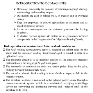
DC motor can satisfy the demands of load requiring high starting,
accelerating and retarding torques.
DC motors are used in rolling mills, in traction and in overhead
cranes.
They are employed in control applications as actuators and as
speed or position sensors.
Its use as a motor-generator (ac motor-dc generator) for feeding
dc drives .
In electric traction systems dc motors act as generators for brief
time periods in the “regenerative” or “dynamic braking” mode.
Basic operation and constructional features of a dc machine are :
The field winding (concentrated type) is mounted on salient-poles on the
stator and the armature winding (distributed type) is wound in slots on a
cylindrical rotor.
The magnetic circuit of a dc machine consists of the armature magnetic
material (core), the air-gap, field poles and yoke.
The interpoles or commutation poles are narrow poles fixed to the yoke,
midway between the main field poles.
The use of an electric field winding is to establish a magnetic field in the
magnetic circuit.
The armature winding is connected to the external power source through a
commutator-brush system which is a mechanical rectifying (switching)
device for converting the alternating currents and induced emfs of the
armature to dc form.
INTRODUCTION TO DC MACHINES
3. ARMATURE WINDING AND COMMUTATOR
A dc machine is a heteropolar structure with stationary poles and
the rotating armature.
An alternating emf of the same wave shape as that of B-wave is
induced in every coil.
As the armature rotates, the emfs induced in the belt of coil-sides
under a given pole is unidirectional and the pattern alternates from
pole to pole as shown in Fig. 7.3 for a 4-pole machine.
The coil side current pattern is the same as the emf pattern.
There is also rectification process which is carried out by
mechanical rectifier comprising commutator-brush assembly.
S
3
4. 4
Commutator-BrushAssembly
The commutator is a cylindrical assembly of wedge-shaped copper
segments insulated from one another and the shaft by thin mica or
micanite sheets.
Each commutator segment forms the junction between two
armature coils (“finish” of one coil and “start” of the other).
In large machines flat copper strips known as risers are used
forming clip connections to armature bar conductors.
A double-layer winding is universally adopted in dc machines.
The coils are continuously connected “finish” to “start” to form a
closed winding.
5. Stationary carbon brushes are placed in contact with the commutator
under spring pressure.
The brushes are electrically placed in the magnetic neutral regions
where the armature coils have almost zero induced emf.
At one brush the current constantly flows out and at the next brush the
current flows in. This occurs at all brush pairs. The adjoining brushes
are at constant dc voltage and the coils in series between the two
constitute one parallel path.
As a coil crosses the brush position, the current in it must reverse which
is the commutation process.
5
6. 6
Two types of armatures windings are mostly employed for DC
machines are known as Lap Winding and Wave Winding.
In a lap winding, the number of parallel paths
(a) is always equal to the number of poles.
(b) and also to the number of brushes.
In wave windings, the number of parallel paths
(a) is always two and there may be two or more brush positions
. https://www.youtube.com/watch?v=wex3ZenASl0
Armature Windings
Choice between Lap and Wave Windings
Wave winding’s greatest attraction is that it does not require
equalizer rings* which means a less expensive machine
compared to lap winding.
Lap winding has the advantage of a larger number of parallel
paths and lower conductor current (Ic = Ia/A) and is therefore
adopted for low-voltage high-current machines.
The use of wave winding is prohibited for armature currents
exceeding 300 A because of certain commutation difficulties.
7. 7
Pole-pitch : The periphery of the armature is spanned by the
number of poles of the generator. i.e. the distance between two
adjacent poles in terms of number of armature conductor spanned.
It is equal to the number of armature conductors (or armature
slots) per pole. If there are 400 conductors and 4 poles, then pole
pitch is 400/4= 100 conductor.
Coil span or Coil pitch : It is the distance, measured in terms of
armature slots (or armature conductors), between two sides of a coil.
Terminologies of Armature Coil
8. 8
Back Pitch : The distance, measured in terms of the armature
conductors which a coil advances on the back of the armature is
called back pitch and is denoted by Yb.
It is equal 'to the number difference of the conductors connected to a
given segment of the commutator.
Front Pitch : The number of armature conductors spanned by a coil
on the front (or commutator end of an armature) is called the front
pitch and is designated by Yf as shown in above figure
Alternatively, it can be defined as the distance (in terms of armature
conductors) between the second conductor of one coil and the first
conductor of the next coil which are connected together to commutator
end of the armature.
Terminologies of Armature Coil
9. 9
Resultant Pitch : It is the distance between the starting end of coil
sides of one coil and the starting end of coil sides of the next coil to
which it is connected as shown in figure below represented by (Yr ).
Commutator Pitch (Yc) :It is the distance (measured in
commutator bars or segments) between the segments to which the
two ends of a coil are connected as shown in figure below
for lap winding : Yc is the difference of Yb and Y f
for wave winding : Yc is the sum of Yb and Yf .
10. 10
Single-layer Winding : It is that winding in which one conductor or one
coil side is placed in each armature slot as shown below. Such a winding is not
much used.
Double-Layer Winding : In this type of winding,' there are two conductors or
coil sides-per slot arranged in two layers. Usually, one side of every coil lies in
the upper half of one slot and other side lies in the lower
11. 11
Generated EMF Equation of a Generator.
Let =flux/pole in weber.
Z=total number of armature conductors = No. of slots*No. of conductors/slot.
P=No. of poles. A= No. of parallel paths in armature.
N = armature rotation in rpm E=EMF induced in any parallel path in armature.
Generated EMF=e.m.f. generated in one of the parallel paths.
Average EMF generated/conductor = d
dt
volt
Now, flux cut/conductor in one revolution, d * P web.
Number of revolution per second =N/60;
Then, time for one revolution, dt=60/N second
Hence according to Faraday's laws of electromagnetic induction,
12. 12
Generated EMF Equation of a Generator.
Eg=
NPϕZ
60 A
=
PZ 2ᴨNϕ
2ᴨA 60
= Kaϕωm
where ωm=
2ᴨN
60
( angular speed of rotation of armature in mech. rad/sec)
Ka=
PZ
2ᴨA
is machine constant .
Example : A 4 pole, long-shunt, compound generator supplies
100 A at a terminal voltage of 500 V. If armature resistance is
0.02 Ω, series field resistance it 0.04 Ω and shunt field resistance
100 Ω, find the generated EMF. Take drop per brush as 1 V,
Neglect armature reaction.
13. 13
Solution:
Step 1 : Draw the circuit diagram of long shunt compound
generator
Brushes
14. 14
Example 2. A 20 kW compound generator works on full load
with a terminal voltage of 250 V. The armature, series and shunt
windings have resistances of 0.05, 0.025 and 100
respectively. Calculate the total EMF generated in the armature
when the machine is connected as short shunt.
Solution:
Generator voltage is shown in
Load current = 20000/250 = 80 A
Voltage drop in the series windings = 80*0.025 = 2V
Voltage across shunt winding = 252 V.
15. 15
Example 3 A 4 pole, lap wound, DC shunt generator has a useful
flux per pole of 0.07 Wb. The armature winding consists of 220
turns each of 0.004 resistance. Calculate the terminal voltage
when running at 900 rpm if the armature current is 50 A.
Solution
Since each turn has two sides,
Z = 220 x 2 = 440 ; N=900 rpm ; = 0.07 Wb ; P = A = 4
17. 17
Vt (armature terminal voltage) = Ea – IaRa ; Ea > Vt
Thus a dc machine is generating if
its armature induced emf (Ea) is more than its terminal voltage (Vt).
The electromagnetic power converted from mechanical to electrical
form is
EaIa = Pelect(out)|gross = Pmech(in)|net
The net electrical power output is
P0 = Vt Ia ( where Vt = Va & Ea = Eg
)
Also,
EaIa – Vt Ia = Ia2
Ra
= armature copper-loss (inclusive of brush loss) and
Pmech(in)|gross = shaft power = Pmech(in)|net + rotational loss
Power Balance
Mechanical power = ωmT = EaIa
So, T = EaIa / ωm = (Kaϕωm. Ia)/ ωm
T = (Kaϕ Ia ) where Ka=
PZ
2ᴨA
Again , ϕ ∝ If => , ϕ = KfIf
I = field current and K = field constant
18. 18
Armature Reaction:
The armature m.m.f. produces two undesirable effects on the
main field flux . These effects are called Armature Reaction.
(i) net reduction in the main field flux per pole thus
further reduction in the generated voltage and
electromagnetic torque.
(ii) distortion of the main field flux wave along the air-
gap periphery, which influences the limits of successful
commutation in d.c. machines.
20. 20
The path of the armature flux is perpendicular to the path of the main-field flux.
Hence armature flux has entirely cross-magnetizing effect on the main field flux.
The armature flux aids the main field flux at upper end of North-pole and at the
lower end of S-pole. So, at these two pole ends (or tips), the armature flux
strengthens the main field flux. Also the armature flux weakens the main field flux at
lower end of North-pole and at the upper end of S-pole. So, again at these two pole
ends (or tips), the armature flux weakens the main field flux.
21. 21
It may therefore be stated from above that net effect of armature flux on the
main-field flux is
(i) to distort the main-field flux thereby causing non-uniform distribution of flux
under the main poles,
(ii) to shift the MNA in the direction of rotation for a generator.
MNA is always perpendicular to the resultant air gap flux.
(iii) to reduce the main-field flux from its no-load value.
Detrimental Effects Of Armature Reaction In DC
Machines
By distortion of main field flux following problems are caused:
(i) Rise in iron losses,
(ii) poor commutation and
(iii) sparking at the brushes.
whereas the reduction in field flux
(i) influences the cost of field winding.
22. 22
Methods of limiting the effects of armature reaction
1. High-reluctance pole tips:
If the reluctance of the pole tips is increased, then the magnitude of
armature cross flux is reduced and the distortion of the resultant flux
density wave is minimised.
2. Reduction in armature flux :
To reduce the armature cross flux is to create more reluctance in the
path of armature flux without reducing the main field flux.
By using field-pole laminations having several rectangular holes
punched in them.
The reluctance offered to armature flux is increased due to four air-gap
openings introduced in the path of cross flux.
As a result armature cross flux is reduced considerably, whereas the
main-field flux remains almost unaffected.
23. 23
3. Strong main-field flux:. During the design of a dc machine, it
should be ensured that:
The main field mmf is sufficiently strong in comparison with full-load
armature mmf.
Greater the ratio of main field mmf to full-load armature mmf, less is the
distortion produced by armature cross flux.
4. Interpoles. The effect of armature reaction in the interpolar zone can
be overcome by interpoles, placed in between the main poles.
The magnetic axis of interpole winding is in line with the
quadrature axis.
Interpole winding is connected in series with armature so that interpole
mmf is able to neutralize the effect of armature mmf in the interpolar
zone at all levels of load current.
.
24. 24
5. Compensating winding. The effect of armature reaction under the
pole shoes can be limited by using compensating winding. This winding
is embedded in slots cut in the pole faces of the dc machine. This is the
best, but the most expensive method.
Effect of Brush Shift
Armature reaction shifts the MNA in the direction of rotation in a generator.
The brushes are along the GNA. The coils undergoing commutation have,
rotational e.m.f. induced in them.
As a consequence, sparking and poor commutation occurs.
If the brushes are given a shift through an angle θ, no rotational e.m.f. would be
generated in the coils undergoing commutation.
It would result in smooth commutation if the brushes are given a forward shift .
In this section, the effect of brush shift in the direction of rotation (called forward
shift) is investigated.
25. 25
The armature flux Φa = OB must be along the brush axis as before.
Flux Φa can now be decomposed into two components ; OC and OD as shown in
Fig. 4.21 (b).
The component OC = Φa sinθ is opposing the main field flux Φf . Therefore, OC
has a demagnetizing effect on the main-field flux.
The other component OD, being perpendicular to the main flux Φf , is the cross
magnetizing effect OD= Φa cosθ .
26. 26
Draw RS making an angle θ with respect to GNA and on the other side
of brush shift, Fig. 4.21 (a). The total armature ampere turns can now be
divided into two groups as illustrated in Fig. 4.22. The conductors
shown in angle ROP and QOS or the conductors lying in angle 4θ for
every 360° electrical (or 2θ for every 180° electrical) are producing a
flux opposite to the main field flux., This can be verified by the right-
hand grip rule. Hence the ampere turns due to the conductors
contained in 4θ degrees for every 360° electrical are demagnetizing
in nature.
27. 27
Prior to the invention of interpoles, brush this was carried out to
improve the commutation forward in a generator and backward in
a motor. Now-a-days brush shift is never carried out.