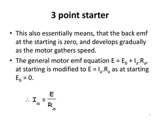
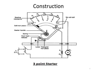
SlideShare a Scribd company logo
3 point starter
Unit 3
1
3 point starter
• A 3 point starter in simple words is a device
that helps in the starting and running of
a shunt wound dc motor or compound wound
dc motor in a safe mode.
• Now the question is why these types of dc
motors require the assistance of the starter in
the first case
2
3 point starter
• The only explanation to that is given by the
presence of back emf Eb, which plays a critical
role in governing the operation of the motor.
• The back emf, develops as the motor
armature starts to rotate in presence of the
magnetic field, by generating action and
counters the supply voltage.
3
Back EMF
• When the armature of a DC motor rotates
under the influence of the driving torque, the
armature conductors move through the
magnetic field and hence emf is induced in
them as in a generator. The induced emf acts
in opposite direction to the applied voltage V
(Lenz's law) and is known as Back EMF or
Counter EMF (Eb).
4
3 point starter
• This also essentially means, that the back emf
at the starting is zero, and develops gradually
as the motor gathers speed.
• The general motor emf equation E = Eb + Ia.Ra,
at starting is modified to E = Ia.Ra as at starting
Eb = 0.
5
3 point starter
• Thus we can well understand from the above
equation that the current will be dangerously
high at starting (as armature resistance Ra is
small) and hence its important that we make
use of a device like the 3 point starter to limit
the starting current to an allowable lower
value.
6
Construction
7
Construction
• Construction wise a starter is a variable
resistance, integrated into number of sections
as shown in the figure .
• The contact points of these sections are called
studs and are shown separately as OFF, 1,
2,3,4,5, RUN.
8
Construction
• Other than that there are 3 main points, referred
to as
1. ‘L’ Line terminal. (Connected to positive of
supply.)
2. ‘A’ Armature terminal. (Connected to the
armature winding.)
3. ‘F’ Field terminal. (Connected to the field
winding.)
9
Construction
• And from there it gets the name 3 point starter
• The Point ‘L’ is connected to an electromagnet
called overload release (OLR) as shown in the
figure.
• The other end of ‘OLR’ is connected to the lower
end of conducting lever of starter handle where a
spring is also attached with it and the starter
handle contains also a soft iron piece housed on
it.
10
Construction
• This handle is free to move to the other side
RUN against the force of the spring.
• This spring brings back the handle to its
original OFF position under the influence of its
own force.
• Another parallel path is derived from the stud
’1′, given to the another electromagnet called
No Volt Coil (NVC)which is further connected
to terminal ‘F’.
11
Construction
• The starting resistance at starting is entirely in
series with the armature. The OLR and NVC
acts as the two protecting devices of the
starter.
12
Working of Three Point Starter
• To start with the handle is in the OFF position
when the supply to the d.c. motor is switched
on.
• Then handle is slowly moved against the
spring force to make a contact with stud No. 1.
• At this point, field winding of the shunt or the
compound motor gets supply through the
parallel path provided to starting resistance,
through No Voltage Coil.
13
Working of Three Point Starter
• While entire starting resistance comes in series
with the armature.
• The high starting armature current thus gets
limited as the current equation at this stage
becomes Ia = E/(Ra+Rst).
• As the handle is moved further, it goes on making
contact with studs 2, 3, 4 etc.,
• Thus gradually cutting off the series resistance
from the armature circuit as the motor gathers
speed.
14
Working of Three Point Starter
• Finally when the starter handle is in ‘RUN’
position, the entire starting resistance is
eliminated and the motor runs with normal
speed.
• This is because back emf is developed
consequently with speed to counter the
supply voltage and reduce the armature
current.
15
Working of Three Point Starter
• So the external resistance is not required
anymore, and is removed for optimum operation.
• The handle is moved manually from OFF to the
RUN position with development of speed. Now
the obvious question is once the handle is taken
to the RUN position how is it supposed to stay
there, as long as motor is running ?
• To find the answer to this question let us look
into the working of No Voltage Coil.
16
Working of No Voltage Coil of 3 point
starter
• The supply to the field winding is derived
through No Voltage Coil.
• So when field current flows, the NVC is
magnetized.
• Now when the handle is in the ‘RUN’ position,
soft iron piece connected to the handle and
gets attracted by the magnetic force produced
by NVC, because of flow of current through it.
17
Working of No Voltage Coil of 3 point
starter
• The NVC is designed in such a way that it
holds the handle in ‘RUN’ position against the
force of the spring as long as supply is given to
the motor.
• Thus NVC holds the handle in the ‘RUN’
position and hence also called hold on coil.
18
Working of No Voltage Coil of 3 point
starter
• Now when there is any kind of supply failure,
the current flow through NVC is affected and it
immediately looses its magnetic property and
is unable to keep the soft iron piece on the
handle, attracted.
• At this point under the action of the spring
force, the handle comes back to OFF position,
opening the circuit and thus switching off the
motor.
19
Working of No Voltage Coil of 3 point
starter
• So due to the combination of NVC and the
spring, the starter handle always comes back
to OFF position whenever there is any supply
problems.
• Thus it also acts as a protective device
safeguarding the motor from any kind of
abnormality.
20
Drawbacks of a Three Point Starter
• To increase the speed of the motor field
resistance can be increased.
• Therefore current through the shunt field is
reduced.
• Field current becomes very low which results
in holding electromagnet too weak to
overcome the force exerted by the spring.
21
Thank you
22

More Related Content

What's hot

Slip power recovery schemes EDC
Slip power recovery schemes EDC Slip power recovery schemes EDC
Slip power recovery schemes EDC
STALLONRAJ
 
Dc machines (Generator & Motor)
Dc machines (Generator & Motor)Dc machines (Generator & Motor)
Dc machines (Generator & Motor)
Mohammed Waris Senan
 
transformer slide prsentation
transformer slide prsentation transformer slide prsentation
transformer slide prsentation
abu jubayer
 
PERMANENT MAGNET BRUSHLESS DC MOTOR
PERMANENT MAGNET BRUSHLESS DC MOTORPERMANENT MAGNET BRUSHLESS DC MOTOR
PERMANENT MAGNET BRUSHLESS DC MOTOR
Archana Balachandran
 
Choppers
ChoppersChoppers
SYNCHRONOUS MOTOR PROJECT REPORT
SYNCHRONOUS MOTOR PROJECT REPORT SYNCHRONOUS MOTOR PROJECT REPORT
SYNCHRONOUS MOTOR PROJECT REPORT
karmbir saini
 
Single phase im-lecture_10_1
Single phase im-lecture_10_1Single phase im-lecture_10_1
Single phase im-lecture_10_1
أشرف أمجد الشريف
 
speed control of three phase induction motor
speed control of three phase induction motorspeed control of three phase induction motor
speed control of three phase induction motor
Ashvani Shukla
 
Three phase transformers
Three phase transformersThree phase transformers
Three phase transformers
W3Edify
 
Dc motor
Dc motorDc motor
Dc motor
Kishan
 
Alternator
AlternatorAlternator
Alternator
Parth Patel
 
Ppt of current transformer
Ppt of current transformerPpt of current transformer
Ppt of current transformer
ROOPAL PANCHOLI
 
three phase induction machine starter
three phase induction machine starterthree phase induction machine starter
three phase induction machine starter
Aditya More
 
ENERGY EFFICIENT MOTORS
ENERGY EFFICIENT MOTORSENERGY EFFICIENT MOTORS
ENERGY EFFICIENT MOTORS
Arigela Harika
 
Electric drive
Electric driveElectric drive
Electric drive
mishradiya
 
Transformer ppt download
Transformer ppt downloadTransformer ppt download
Transformer ppt download
ANKUSHKUMAR407
 
Electrical machines lecture notes
Electrical machines lecture notesElectrical machines lecture notes
Electrical machines lecture notes
IYAKAREMYE Jean De Dieu
 
Variable voltage variable frequency drive
Variable voltage variable frequency driveVariable voltage variable frequency drive
Variable voltage variable frequency drive
bheemanna angadi
 
Construction of dc machines
Construction of dc machinesConstruction of dc machines
Construction of dc machinesRohini Haridas
 

What's hot (20)

Slip power recovery schemes EDC
Slip power recovery schemes EDC Slip power recovery schemes EDC
Slip power recovery schemes EDC
 
Dc machines (Generator & Motor)
Dc machines (Generator & Motor)Dc machines (Generator & Motor)
Dc machines (Generator & Motor)
 
transformer slide prsentation
transformer slide prsentation transformer slide prsentation
transformer slide prsentation
 
PERMANENT MAGNET BRUSHLESS DC MOTOR
PERMANENT MAGNET BRUSHLESS DC MOTORPERMANENT MAGNET BRUSHLESS DC MOTOR
PERMANENT MAGNET BRUSHLESS DC MOTOR
 
Choppers
ChoppersChoppers
Choppers
 
SYNCHRONOUS MOTOR PROJECT REPORT
SYNCHRONOUS MOTOR PROJECT REPORT SYNCHRONOUS MOTOR PROJECT REPORT
SYNCHRONOUS MOTOR PROJECT REPORT
 
Single phase im-lecture_10_1
Single phase im-lecture_10_1Single phase im-lecture_10_1
Single phase im-lecture_10_1
 
speed control of three phase induction motor
speed control of three phase induction motorspeed control of three phase induction motor
speed control of three phase induction motor
 
Three phase transformers
Three phase transformersThree phase transformers
Three phase transformers
 
Dc motor
Dc motorDc motor
Dc motor
 
Alternator
AlternatorAlternator
Alternator
 
Dc motor
Dc motorDc motor
Dc motor
 
Ppt of current transformer
Ppt of current transformerPpt of current transformer
Ppt of current transformer
 
three phase induction machine starter
three phase induction machine starterthree phase induction machine starter
three phase induction machine starter
 
ENERGY EFFICIENT MOTORS
ENERGY EFFICIENT MOTORSENERGY EFFICIENT MOTORS
ENERGY EFFICIENT MOTORS
 
Electric drive
Electric driveElectric drive
Electric drive
 
Transformer ppt download
Transformer ppt downloadTransformer ppt download
Transformer ppt download
 
Electrical machines lecture notes
Electrical machines lecture notesElectrical machines lecture notes
Electrical machines lecture notes
 
Variable voltage variable frequency drive
Variable voltage variable frequency driveVariable voltage variable frequency drive
Variable voltage variable frequency drive
 
Construction of dc machines
Construction of dc machinesConstruction of dc machines
Construction of dc machines
 

Similar to 3 point starter

dc motor starter.pptnmkdssbfhhhhdhhdhhhdh
dc motor starter.pptnmkdssbfhhhhdhhdhhhdhdc motor starter.pptnmkdssbfhhhhdhhdhhhdh
dc motor starter.pptnmkdssbfhhhhdhhdhhhdh
MANOJ KHARADE
 
Stater motor
Stater motorStater motor
Stater motor
Rajput Manthan
 
Induction motor Starters.pp
Induction motor Starters.ppInduction motor Starters.pp
Induction motor Starters.pp
37NMahaLakshmi
 
STARTING AND SPEED CONTROL OF THREE PHASE INDUCTION MOTOR
STARTING AND SPEED CONTROL OF THREE PHASE INDUCTION MOTORSTARTING AND SPEED CONTROL OF THREE PHASE INDUCTION MOTOR
STARTING AND SPEED CONTROL OF THREE PHASE INDUCTION MOTOR
RagulS61
 
4 point starter
4 point starter4 point starter
4 point starter
mpsrekha83
 
Starting methods Of DC Machines
Starting methods Of DC MachinesStarting methods Of DC Machines
Starting methods Of DC Machines
Dinesh Sharma
 
Induction motor 3ph
Induction motor 3phInduction motor 3ph
Induction motor 3ph
Ramaiahsubasri
 
inductionmotor mod4threephaseinductionmotorsquirrelcagemotor.pptx
inductionmotor mod4threephaseinductionmotorsquirrelcagemotor.pptxinductionmotor mod4threephaseinductionmotorsquirrelcagemotor.pptx
inductionmotor mod4threephaseinductionmotorsquirrelcagemotor.pptx
divyababu56
 
chapter 5 (1).pptx
chapter 5 (1).pptxchapter 5 (1).pptx
chapter 5 (1).pptx
deepaMS4
 
Unit 5.pptx
Unit 5.pptxUnit 5.pptx
Unit 5.pptx
NagarajR28
 
Breaking,Types of Electrical Braking system, Regenerative Braking, Plugging ...
Breaking,Types of Electrical Braking system, Regenerative Braking,  Plugging ...Breaking,Types of Electrical Braking system, Regenerative Braking,  Plugging ...
Breaking,Types of Electrical Braking system, Regenerative Braking, Plugging ...
Waqas Afzal
 
Synchronous generator construction
Synchronous generator constructionSynchronous generator construction
Synchronous generator construction
AnilKumarJain19
 
Alternator and 3 phase induction motor
Alternator and 3 phase induction motorAlternator and 3 phase induction motor
Alternator and 3 phase induction motor
johny renoald
 
industry 4.0-Revolution-chapter3-DC Motors.pptx
industry 4.0-Revolution-chapter3-DC Motors.pptxindustry 4.0-Revolution-chapter3-DC Motors.pptx
industry 4.0-Revolution-chapter3-DC Motors.pptx
AndrieKienFanerPalom
 
Permanent magnet brushless dc motors ppt
Permanent magnet brushless dc motors pptPermanent magnet brushless dc motors ppt
Permanent magnet brushless dc motors ppt
srmrithi
 
ppts D.c motors.pptx
ppts D.c motors.pptxppts D.c motors.pptx
ppts D.c motors.pptx
BalramGyadari1
 
Single-phase-Induction-motor1.ppt.pptx
Single-phase-Induction-motor1.ppt.pptxSingle-phase-Induction-motor1.ppt.pptx
Single-phase-Induction-motor1.ppt.pptx
datamboli
 
Generators
GeneratorsGenerators
Generators
Karthik Selvan. P
 

Similar to 3 point starter (20)

dc motor starter.pptnmkdssbfhhhhdhhdhhhdh
dc motor starter.pptnmkdssbfhhhhdhhdhhhdhdc motor starter.pptnmkdssbfhhhhdhhdhhhdh
dc motor starter.pptnmkdssbfhhhhdhhdhhhdh
 
Stater motor
Stater motorStater motor
Stater motor
 
Induction motor Starters.pp
Induction motor Starters.ppInduction motor Starters.pp
Induction motor Starters.pp
 
STARTING AND SPEED CONTROL OF THREE PHASE INDUCTION MOTOR
STARTING AND SPEED CONTROL OF THREE PHASE INDUCTION MOTORSTARTING AND SPEED CONTROL OF THREE PHASE INDUCTION MOTOR
STARTING AND SPEED CONTROL OF THREE PHASE INDUCTION MOTOR
 
4 point starter
4 point starter4 point starter
4 point starter
 
Starters
StartersStarters
Starters
 
Starting methods Of DC Machines
Starting methods Of DC MachinesStarting methods Of DC Machines
Starting methods Of DC Machines
 
Induction motor 3ph
Induction motor 3phInduction motor 3ph
Induction motor 3ph
 
inductionmotor mod4threephaseinductionmotorsquirrelcagemotor.pptx
inductionmotor mod4threephaseinductionmotorsquirrelcagemotor.pptxinductionmotor mod4threephaseinductionmotorsquirrelcagemotor.pptx
inductionmotor mod4threephaseinductionmotorsquirrelcagemotor.pptx
 
chapter 5 (1).pptx
chapter 5 (1).pptxchapter 5 (1).pptx
chapter 5 (1).pptx
 
DC Motors
DC MotorsDC Motors
DC Motors
 
Unit 5.pptx
Unit 5.pptxUnit 5.pptx
Unit 5.pptx
 
Breaking,Types of Electrical Braking system, Regenerative Braking, Plugging ...
Breaking,Types of Electrical Braking system, Regenerative Braking,  Plugging ...Breaking,Types of Electrical Braking system, Regenerative Braking,  Plugging ...
Breaking,Types of Electrical Braking system, Regenerative Braking, Plugging ...
 
Synchronous generator construction
Synchronous generator constructionSynchronous generator construction
Synchronous generator construction
 
Alternator and 3 phase induction motor
Alternator and 3 phase induction motorAlternator and 3 phase induction motor
Alternator and 3 phase induction motor
 
industry 4.0-Revolution-chapter3-DC Motors.pptx
industry 4.0-Revolution-chapter3-DC Motors.pptxindustry 4.0-Revolution-chapter3-DC Motors.pptx
industry 4.0-Revolution-chapter3-DC Motors.pptx
 
Permanent magnet brushless dc motors ppt
Permanent magnet brushless dc motors pptPermanent magnet brushless dc motors ppt
Permanent magnet brushless dc motors ppt
 
ppts D.c motors.pptx
ppts D.c motors.pptxppts D.c motors.pptx
ppts D.c motors.pptx
 
Single-phase-Induction-motor1.ppt.pptx
Single-phase-Induction-motor1.ppt.pptxSingle-phase-Induction-motor1.ppt.pptx
Single-phase-Induction-motor1.ppt.pptx
 
Generators
GeneratorsGenerators
Generators
 

More from mpsrekha83

Line coding
Line codingLine coding
Line coding
mpsrekha83
 
Delta modulation
Delta modulationDelta modulation
Delta modulation
mpsrekha83
 
Block diagram of digital communication
Block diagram of digital communicationBlock diagram of digital communication
Block diagram of digital communication
mpsrekha83
 
Adaptive differential pcm
Adaptive differential pcmAdaptive differential pcm
Adaptive differential pcm
mpsrekha83
 
Adaptive delta modulation
Adaptive delta modulationAdaptive delta modulation
Adaptive delta modulation
mpsrekha83
 
Eye pattern
Eye patternEye pattern
Eye pattern
mpsrekha83
 
Digital modulation techniques
Digital modulation techniquesDigital modulation techniques
Digital modulation techniques
mpsrekha83
 
Comparison of qam and psk
Comparison of qam and pskComparison of qam and psk
Comparison of qam and psk
mpsrekha83
 
Pn sequence
Pn sequencePn sequence
Pn sequence
mpsrekha83
 
Spread spectrum
Spread spectrumSpread spectrum
Spread spectrum
mpsrekha83
 
8086 signals
8086 signals8086 signals
8086 signals
mpsrekha83
 
System bus timing 8086
System bus timing 8086System bus timing 8086
System bus timing 8086
mpsrekha83
 
Pulse modulation
Pulse modulationPulse modulation
Pulse modulation
mpsrekha83
 
AM diode envelope demodulator
AM diode envelope demodulatorAM diode envelope demodulator
AM diode envelope demodulator
mpsrekha83
 
Byte and string manipulation 8086
Byte and string manipulation 8086Byte and string manipulation 8086
Byte and string manipulation 8086
mpsrekha83
 
Interrupts of 8086
Interrupts of 8086Interrupts of 8086
Interrupts of 8086
mpsrekha83
 
Super heterodyne receiver
Super heterodyne receiverSuper heterodyne receiver
Super heterodyne receiver
mpsrekha83
 
Pre emphasis and de-emphasis
Pre emphasis and de-emphasisPre emphasis and de-emphasis
Pre emphasis and de-emphasis
mpsrekha83
 
Fm generation
Fm generationFm generation
Fm generation
mpsrekha83
 
Fm demodulation using zero crossing detector
Fm demodulation using zero crossing detectorFm demodulation using zero crossing detector
Fm demodulation using zero crossing detector
mpsrekha83
 

More from mpsrekha83 (20)

Line coding
Line codingLine coding
Line coding
 
Delta modulation
Delta modulationDelta modulation
Delta modulation
 
Block diagram of digital communication
Block diagram of digital communicationBlock diagram of digital communication
Block diagram of digital communication
 
Adaptive differential pcm
Adaptive differential pcmAdaptive differential pcm
Adaptive differential pcm
 
Adaptive delta modulation
Adaptive delta modulationAdaptive delta modulation
Adaptive delta modulation
 
Eye pattern
Eye patternEye pattern
Eye pattern
 
Digital modulation techniques
Digital modulation techniquesDigital modulation techniques
Digital modulation techniques
 
Comparison of qam and psk
Comparison of qam and pskComparison of qam and psk
Comparison of qam and psk
 
Pn sequence
Pn sequencePn sequence
Pn sequence
 
Spread spectrum
Spread spectrumSpread spectrum
Spread spectrum
 
8086 signals
8086 signals8086 signals
8086 signals
 
System bus timing 8086
System bus timing 8086System bus timing 8086
System bus timing 8086
 
Pulse modulation
Pulse modulationPulse modulation
Pulse modulation
 
AM diode envelope demodulator
AM diode envelope demodulatorAM diode envelope demodulator
AM diode envelope demodulator
 
Byte and string manipulation 8086
Byte and string manipulation 8086Byte and string manipulation 8086
Byte and string manipulation 8086
 
Interrupts of 8086
Interrupts of 8086Interrupts of 8086
Interrupts of 8086
 
Super heterodyne receiver
Super heterodyne receiverSuper heterodyne receiver
Super heterodyne receiver
 
Pre emphasis and de-emphasis
Pre emphasis and de-emphasisPre emphasis and de-emphasis
Pre emphasis and de-emphasis
 
Fm generation
Fm generationFm generation
Fm generation
 
Fm demodulation using zero crossing detector
Fm demodulation using zero crossing detectorFm demodulation using zero crossing detector
Fm demodulation using zero crossing detector
 

Recently uploaded

J.Yang, ICLR 2024, MLILAB, KAIST AI.pdf
J.Yang,  ICLR 2024, MLILAB, KAIST AI.pdfJ.Yang,  ICLR 2024, MLILAB, KAIST AI.pdf
J.Yang, ICLR 2024, MLILAB, KAIST AI.pdf
MLILAB
 
Sachpazis:Terzaghi Bearing Capacity Estimation in simple terms with Calculati...
Sachpazis:Terzaghi Bearing Capacity Estimation in simple terms with Calculati...Sachpazis:Terzaghi Bearing Capacity Estimation in simple terms with Calculati...
Sachpazis:Terzaghi Bearing Capacity Estimation in simple terms with Calculati...
Dr.Costas Sachpazis
 
NO1 Uk best vashikaran specialist in delhi vashikaran baba near me online vas...
NO1 Uk best vashikaran specialist in delhi vashikaran baba near me online vas...NO1 Uk best vashikaran specialist in delhi vashikaran baba near me online vas...
NO1 Uk best vashikaran specialist in delhi vashikaran baba near me online vas...
Amil Baba Dawood bangali
 
The role of big data in decision making.
The role of big data in decision making.The role of big data in decision making.
The role of big data in decision making.
ankuprajapati0525
 
ASME IX(9) 2007 Full Version .pdf
ASME IX(9)  2007 Full Version       .pdfASME IX(9)  2007 Full Version       .pdf
ASME IX(9) 2007 Full Version .pdf
AhmedHussein950959
 
Investor-Presentation-Q1FY2024 investor presentation document.pptx
Investor-Presentation-Q1FY2024 investor presentation document.pptxInvestor-Presentation-Q1FY2024 investor presentation document.pptx
Investor-Presentation-Q1FY2024 investor presentation document.pptx
AmarGB2
 
ML for identifying fraud using open blockchain data.pptx
ML for identifying fraud using open blockchain data.pptxML for identifying fraud using open blockchain data.pptx
ML for identifying fraud using open blockchain data.pptx
Vijay Dialani, PhD
 
Design and Analysis of Algorithms-DP,Backtracking,Graphs,B&B
Design and Analysis of Algorithms-DP,Backtracking,Graphs,B&BDesign and Analysis of Algorithms-DP,Backtracking,Graphs,B&B
Design and Analysis of Algorithms-DP,Backtracking,Graphs,B&B
Sreedhar Chowdam
 
Nuclear Power Economics and Structuring 2024
Nuclear Power Economics and Structuring 2024Nuclear Power Economics and Structuring 2024
Nuclear Power Economics and Structuring 2024
Massimo Talia
 
power quality voltage fluctuation UNIT - I.pptx
power quality voltage fluctuation UNIT - I.pptxpower quality voltage fluctuation UNIT - I.pptx
power quality voltage fluctuation UNIT - I.pptx
ViniHema
 
Cosmetic shop management system project report.pdf
Cosmetic shop management system project report.pdfCosmetic shop management system project report.pdf
Cosmetic shop management system project report.pdf
Kamal Acharya
 
Runway Orientation Based on the Wind Rose Diagram.pptx
Runway Orientation Based on the Wind Rose Diagram.pptxRunway Orientation Based on the Wind Rose Diagram.pptx
Runway Orientation Based on the Wind Rose Diagram.pptx
SupreethSP4
 
Railway Signalling Principles Edition 3.pdf
Railway Signalling Principles Edition 3.pdfRailway Signalling Principles Edition 3.pdf
Railway Signalling Principles Edition 3.pdf
TeeVichai
 
HYDROPOWER - Hydroelectric power generation
HYDROPOWER - Hydroelectric power generationHYDROPOWER - Hydroelectric power generation
HYDROPOWER - Hydroelectric power generation
Robbie Edward Sayers
 
Architectural Portfolio Sean Lockwood
Architectural Portfolio Sean LockwoodArchitectural Portfolio Sean Lockwood
Architectural Portfolio Sean Lockwood
seandesed
 
Fundamentals of Electric Drives and its applications.pptx
Fundamentals of Electric Drives and its applications.pptxFundamentals of Electric Drives and its applications.pptx
Fundamentals of Electric Drives and its applications.pptx
manasideore6
 
Gen AI Study Jams _ For the GDSC Leads in India.pdf
Gen AI Study Jams _ For the GDSC Leads in India.pdfGen AI Study Jams _ For the GDSC Leads in India.pdf
Gen AI Study Jams _ For the GDSC Leads in India.pdf
gdsczhcet
 
Standard Reomte Control Interface - Neometrix
Standard Reomte Control Interface - NeometrixStandard Reomte Control Interface - Neometrix
Standard Reomte Control Interface - Neometrix
Neometrix_Engineering_Pvt_Ltd
 
Student information management system project report ii.pdf
Student information management system project report ii.pdfStudent information management system project report ii.pdf
Student information management system project report ii.pdf
Kamal Acharya
 
H.Seo, ICLR 2024, MLILAB, KAIST AI.pdf
H.Seo,  ICLR 2024, MLILAB,  KAIST AI.pdfH.Seo,  ICLR 2024, MLILAB,  KAIST AI.pdf
H.Seo, ICLR 2024, MLILAB, KAIST AI.pdf
MLILAB
 

Recently uploaded (20)

J.Yang, ICLR 2024, MLILAB, KAIST AI.pdf
J.Yang,  ICLR 2024, MLILAB, KAIST AI.pdfJ.Yang,  ICLR 2024, MLILAB, KAIST AI.pdf
J.Yang, ICLR 2024, MLILAB, KAIST AI.pdf
 
Sachpazis:Terzaghi Bearing Capacity Estimation in simple terms with Calculati...
Sachpazis:Terzaghi Bearing Capacity Estimation in simple terms with Calculati...Sachpazis:Terzaghi Bearing Capacity Estimation in simple terms with Calculati...
Sachpazis:Terzaghi Bearing Capacity Estimation in simple terms with Calculati...
 
NO1 Uk best vashikaran specialist in delhi vashikaran baba near me online vas...
NO1 Uk best vashikaran specialist in delhi vashikaran baba near me online vas...NO1 Uk best vashikaran specialist in delhi vashikaran baba near me online vas...
NO1 Uk best vashikaran specialist in delhi vashikaran baba near me online vas...
 
The role of big data in decision making.
The role of big data in decision making.The role of big data in decision making.
The role of big data in decision making.
 
ASME IX(9) 2007 Full Version .pdf
ASME IX(9)  2007 Full Version       .pdfASME IX(9)  2007 Full Version       .pdf
ASME IX(9) 2007 Full Version .pdf
 
Investor-Presentation-Q1FY2024 investor presentation document.pptx
Investor-Presentation-Q1FY2024 investor presentation document.pptxInvestor-Presentation-Q1FY2024 investor presentation document.pptx
Investor-Presentation-Q1FY2024 investor presentation document.pptx
 
ML for identifying fraud using open blockchain data.pptx
ML for identifying fraud using open blockchain data.pptxML for identifying fraud using open blockchain data.pptx
ML for identifying fraud using open blockchain data.pptx
 
Design and Analysis of Algorithms-DP,Backtracking,Graphs,B&B
Design and Analysis of Algorithms-DP,Backtracking,Graphs,B&BDesign and Analysis of Algorithms-DP,Backtracking,Graphs,B&B
Design and Analysis of Algorithms-DP,Backtracking,Graphs,B&B
 
Nuclear Power Economics and Structuring 2024
Nuclear Power Economics and Structuring 2024Nuclear Power Economics and Structuring 2024
Nuclear Power Economics and Structuring 2024
 
power quality voltage fluctuation UNIT - I.pptx
power quality voltage fluctuation UNIT - I.pptxpower quality voltage fluctuation UNIT - I.pptx
power quality voltage fluctuation UNIT - I.pptx
 
Cosmetic shop management system project report.pdf
Cosmetic shop management system project report.pdfCosmetic shop management system project report.pdf
Cosmetic shop management system project report.pdf
 
Runway Orientation Based on the Wind Rose Diagram.pptx
Runway Orientation Based on the Wind Rose Diagram.pptxRunway Orientation Based on the Wind Rose Diagram.pptx
Runway Orientation Based on the Wind Rose Diagram.pptx
 
Railway Signalling Principles Edition 3.pdf
Railway Signalling Principles Edition 3.pdfRailway Signalling Principles Edition 3.pdf
Railway Signalling Principles Edition 3.pdf
 
HYDROPOWER - Hydroelectric power generation
HYDROPOWER - Hydroelectric power generationHYDROPOWER - Hydroelectric power generation
HYDROPOWER - Hydroelectric power generation
 
Architectural Portfolio Sean Lockwood
Architectural Portfolio Sean LockwoodArchitectural Portfolio Sean Lockwood
Architectural Portfolio Sean Lockwood
 
Fundamentals of Electric Drives and its applications.pptx
Fundamentals of Electric Drives and its applications.pptxFundamentals of Electric Drives and its applications.pptx
Fundamentals of Electric Drives and its applications.pptx
 
Gen AI Study Jams _ For the GDSC Leads in India.pdf
Gen AI Study Jams _ For the GDSC Leads in India.pdfGen AI Study Jams _ For the GDSC Leads in India.pdf
Gen AI Study Jams _ For the GDSC Leads in India.pdf
 
Standard Reomte Control Interface - Neometrix
Standard Reomte Control Interface - NeometrixStandard Reomte Control Interface - Neometrix
Standard Reomte Control Interface - Neometrix
 
Student information management system project report ii.pdf
Student information management system project report ii.pdfStudent information management system project report ii.pdf
Student information management system project report ii.pdf
 
H.Seo, ICLR 2024, MLILAB, KAIST AI.pdf
H.Seo,  ICLR 2024, MLILAB,  KAIST AI.pdfH.Seo,  ICLR 2024, MLILAB,  KAIST AI.pdf
H.Seo, ICLR 2024, MLILAB, KAIST AI.pdf
 

3 point starter

  • 2. 3 point starter • A 3 point starter in simple words is a device that helps in the starting and running of a shunt wound dc motor or compound wound dc motor in a safe mode. • Now the question is why these types of dc motors require the assistance of the starter in the first case 2
  • 3. 3 point starter • The only explanation to that is given by the presence of back emf Eb, which plays a critical role in governing the operation of the motor. • The back emf, develops as the motor armature starts to rotate in presence of the magnetic field, by generating action and counters the supply voltage. 3
  • 4. Back EMF • When the armature of a DC motor rotates under the influence of the driving torque, the armature conductors move through the magnetic field and hence emf is induced in them as in a generator. The induced emf acts in opposite direction to the applied voltage V (Lenz's law) and is known as Back EMF or Counter EMF (Eb). 4
  • 5. 3 point starter • This also essentially means, that the back emf at the starting is zero, and develops gradually as the motor gathers speed. • The general motor emf equation E = Eb + Ia.Ra, at starting is modified to E = Ia.Ra as at starting Eb = 0. 5
  • 6. 3 point starter • Thus we can well understand from the above equation that the current will be dangerously high at starting (as armature resistance Ra is small) and hence its important that we make use of a device like the 3 point starter to limit the starting current to an allowable lower value. 6
  • 8. Construction • Construction wise a starter is a variable resistance, integrated into number of sections as shown in the figure . • The contact points of these sections are called studs and are shown separately as OFF, 1, 2,3,4,5, RUN. 8
  • 9. Construction • Other than that there are 3 main points, referred to as 1. ‘L’ Line terminal. (Connected to positive of supply.) 2. ‘A’ Armature terminal. (Connected to the armature winding.) 3. ‘F’ Field terminal. (Connected to the field winding.) 9
  • 10. Construction • And from there it gets the name 3 point starter • The Point ‘L’ is connected to an electromagnet called overload release (OLR) as shown in the figure. • The other end of ‘OLR’ is connected to the lower end of conducting lever of starter handle where a spring is also attached with it and the starter handle contains also a soft iron piece housed on it. 10
  • 11. Construction • This handle is free to move to the other side RUN against the force of the spring. • This spring brings back the handle to its original OFF position under the influence of its own force. • Another parallel path is derived from the stud ’1′, given to the another electromagnet called No Volt Coil (NVC)which is further connected to terminal ‘F’. 11
  • 12. Construction • The starting resistance at starting is entirely in series with the armature. The OLR and NVC acts as the two protecting devices of the starter. 12
  • 13. Working of Three Point Starter • To start with the handle is in the OFF position when the supply to the d.c. motor is switched on. • Then handle is slowly moved against the spring force to make a contact with stud No. 1. • At this point, field winding of the shunt or the compound motor gets supply through the parallel path provided to starting resistance, through No Voltage Coil. 13
  • 14. Working of Three Point Starter • While entire starting resistance comes in series with the armature. • The high starting armature current thus gets limited as the current equation at this stage becomes Ia = E/(Ra+Rst). • As the handle is moved further, it goes on making contact with studs 2, 3, 4 etc., • Thus gradually cutting off the series resistance from the armature circuit as the motor gathers speed. 14
  • 15. Working of Three Point Starter • Finally when the starter handle is in ‘RUN’ position, the entire starting resistance is eliminated and the motor runs with normal speed. • This is because back emf is developed consequently with speed to counter the supply voltage and reduce the armature current. 15
  • 16. Working of Three Point Starter • So the external resistance is not required anymore, and is removed for optimum operation. • The handle is moved manually from OFF to the RUN position with development of speed. Now the obvious question is once the handle is taken to the RUN position how is it supposed to stay there, as long as motor is running ? • To find the answer to this question let us look into the working of No Voltage Coil. 16
  • 17. Working of No Voltage Coil of 3 point starter • The supply to the field winding is derived through No Voltage Coil. • So when field current flows, the NVC is magnetized. • Now when the handle is in the ‘RUN’ position, soft iron piece connected to the handle and gets attracted by the magnetic force produced by NVC, because of flow of current through it. 17
  • 18. Working of No Voltage Coil of 3 point starter • The NVC is designed in such a way that it holds the handle in ‘RUN’ position against the force of the spring as long as supply is given to the motor. • Thus NVC holds the handle in the ‘RUN’ position and hence also called hold on coil. 18
  • 19. Working of No Voltage Coil of 3 point starter • Now when there is any kind of supply failure, the current flow through NVC is affected and it immediately looses its magnetic property and is unable to keep the soft iron piece on the handle, attracted. • At this point under the action of the spring force, the handle comes back to OFF position, opening the circuit and thus switching off the motor. 19
  • 20. Working of No Voltage Coil of 3 point starter • So due to the combination of NVC and the spring, the starter handle always comes back to OFF position whenever there is any supply problems. • Thus it also acts as a protective device safeguarding the motor from any kind of abnormality. 20
  • 21. Drawbacks of a Three Point Starter • To increase the speed of the motor field resistance can be increased. • Therefore current through the shunt field is reduced. • Field current becomes very low which results in holding electromagnet too weak to overcome the force exerted by the spring. 21