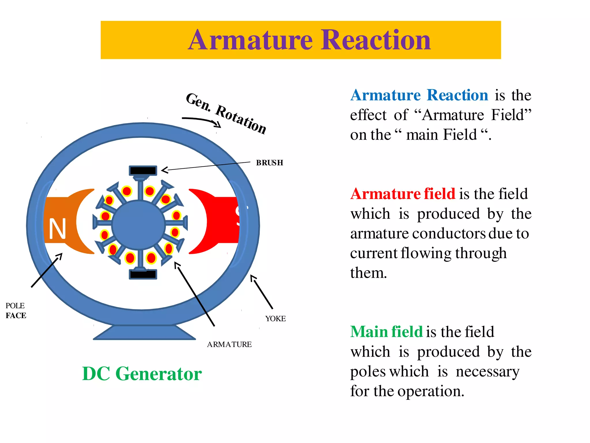
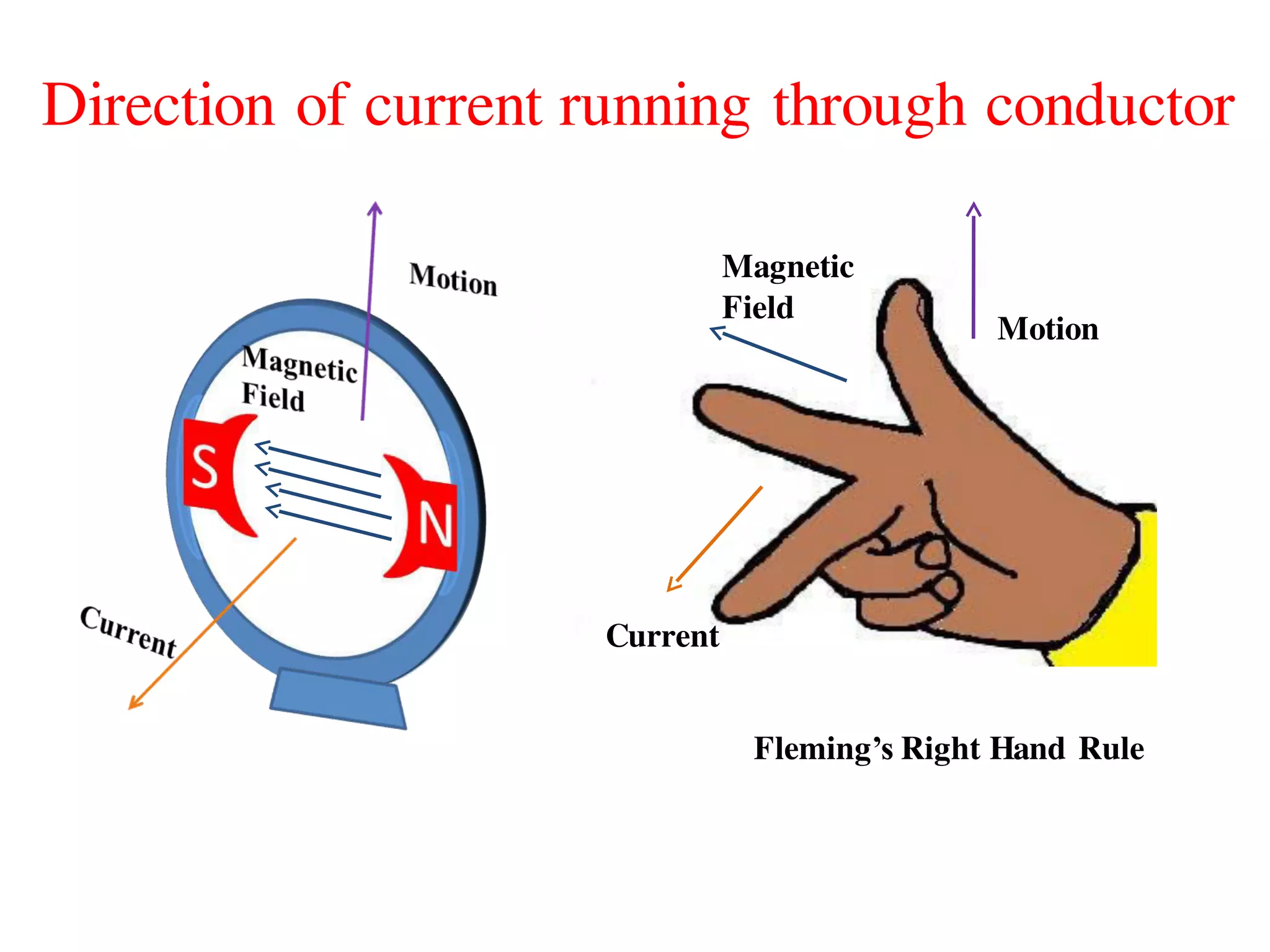
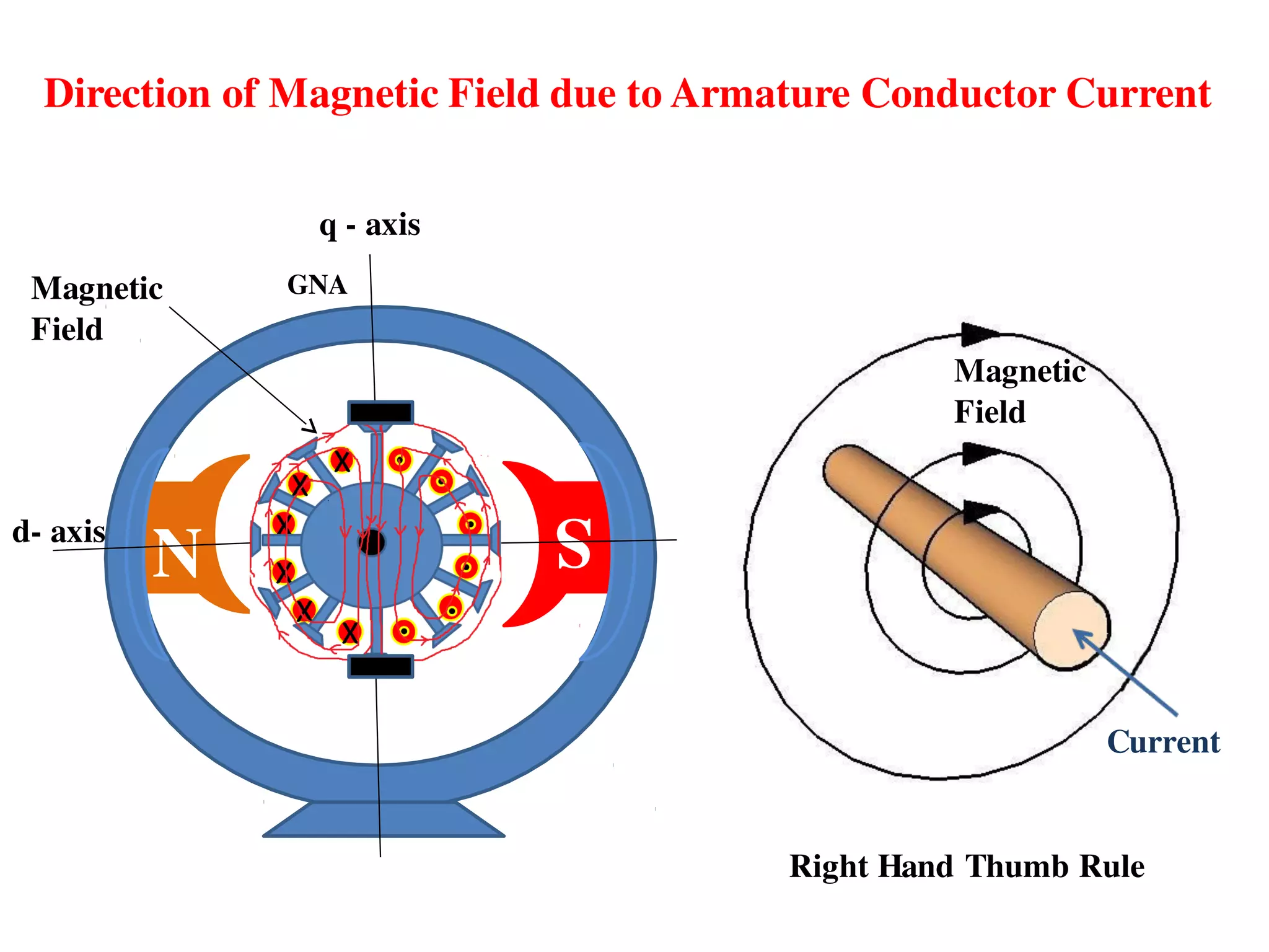
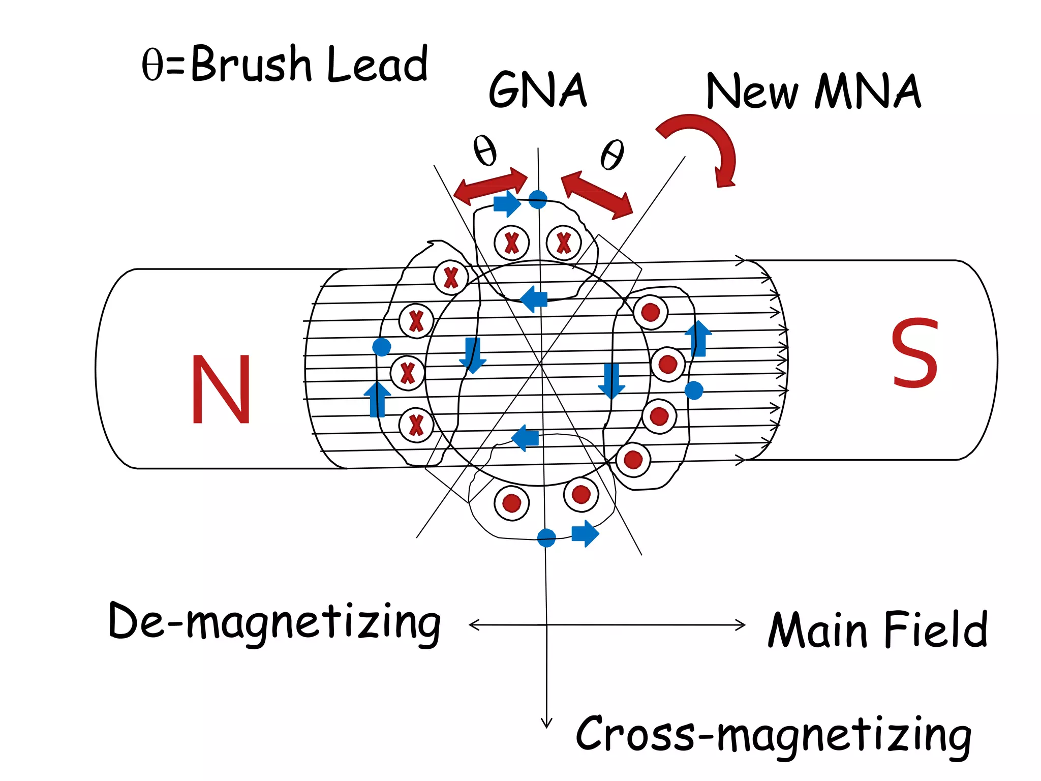
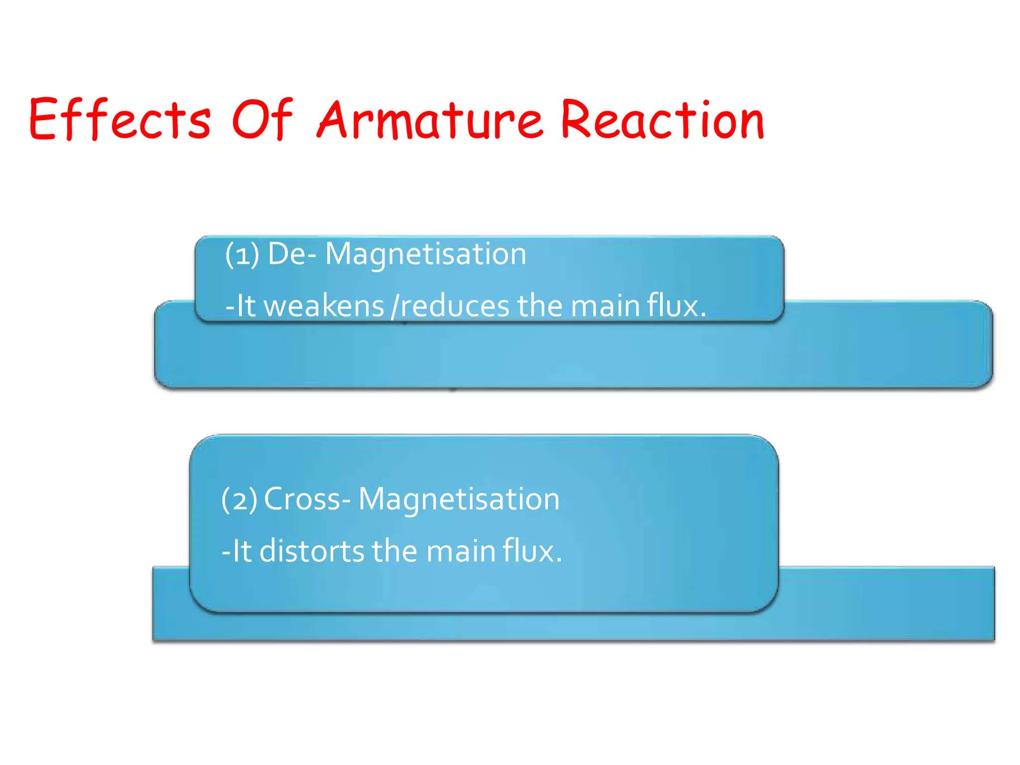
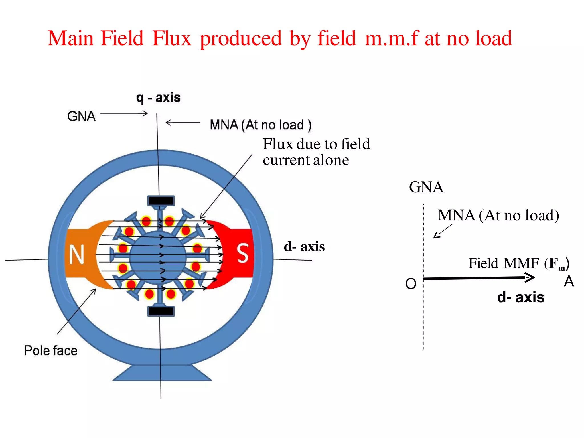
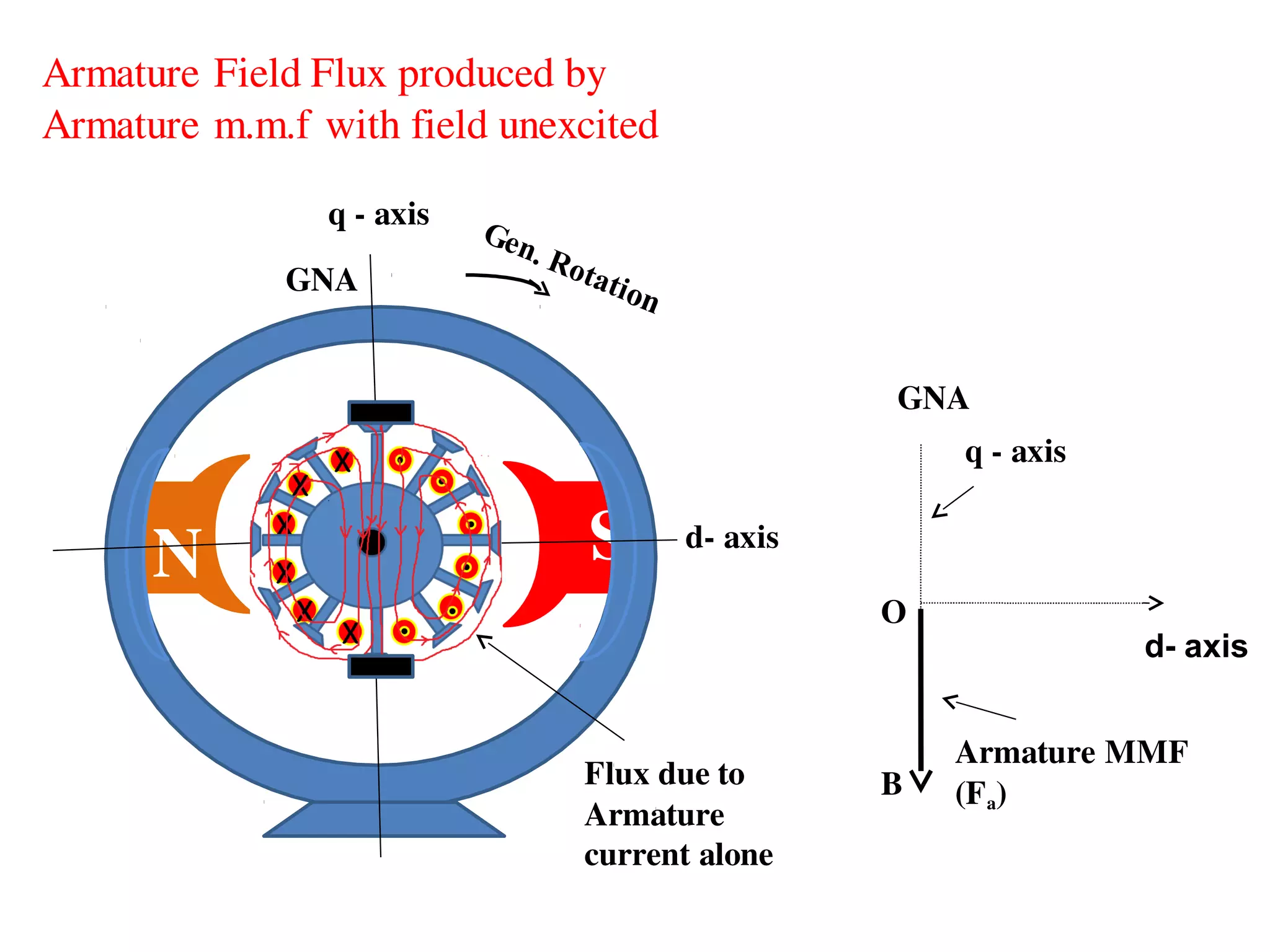
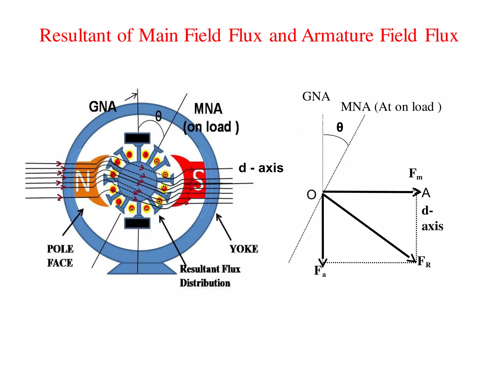
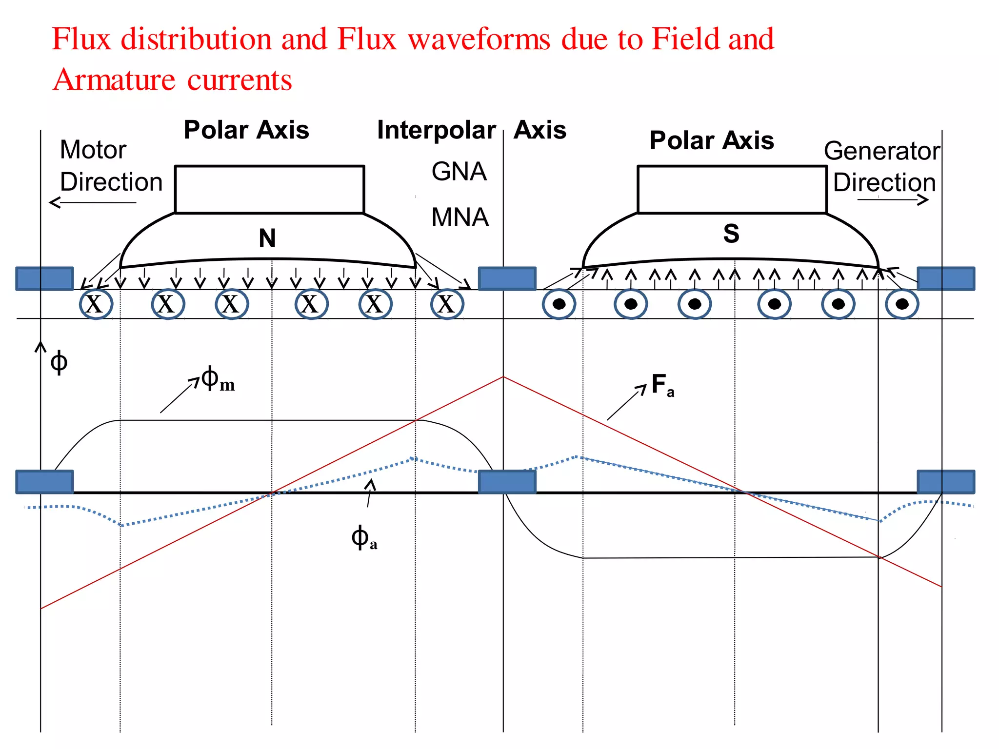
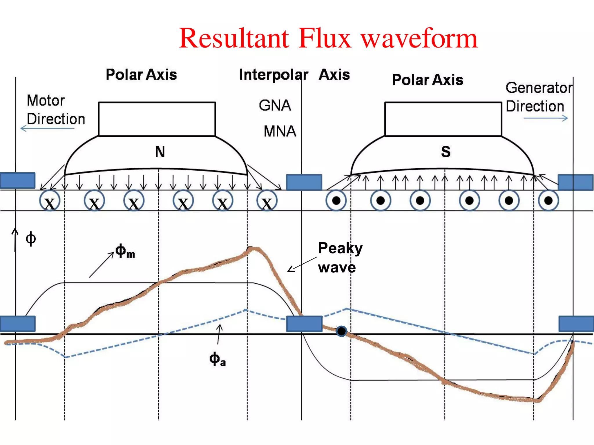
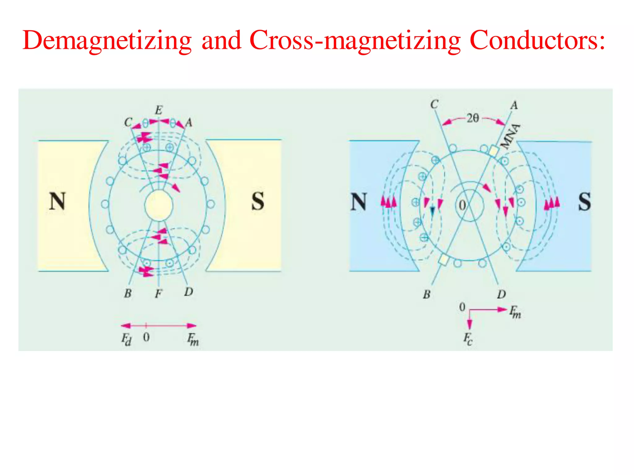
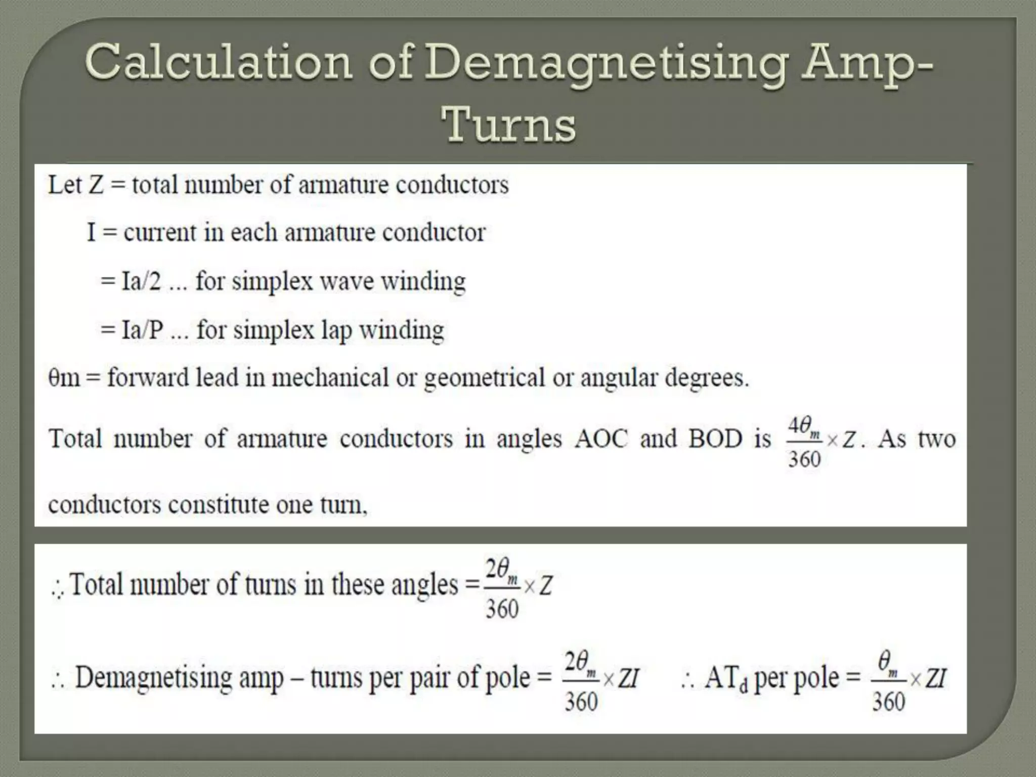
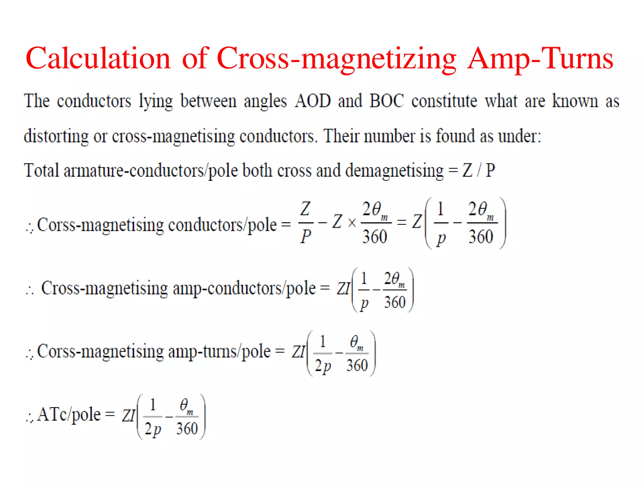
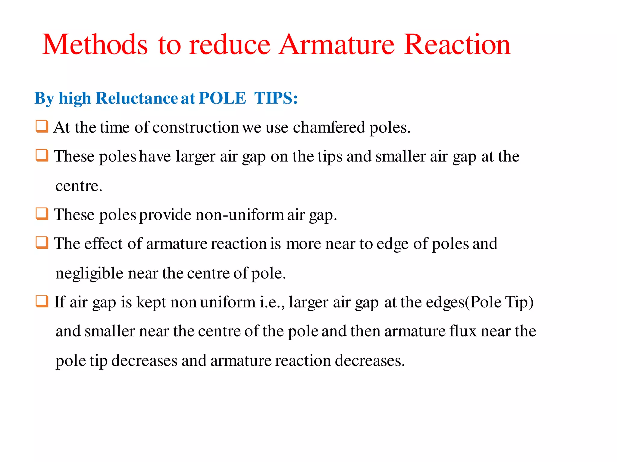
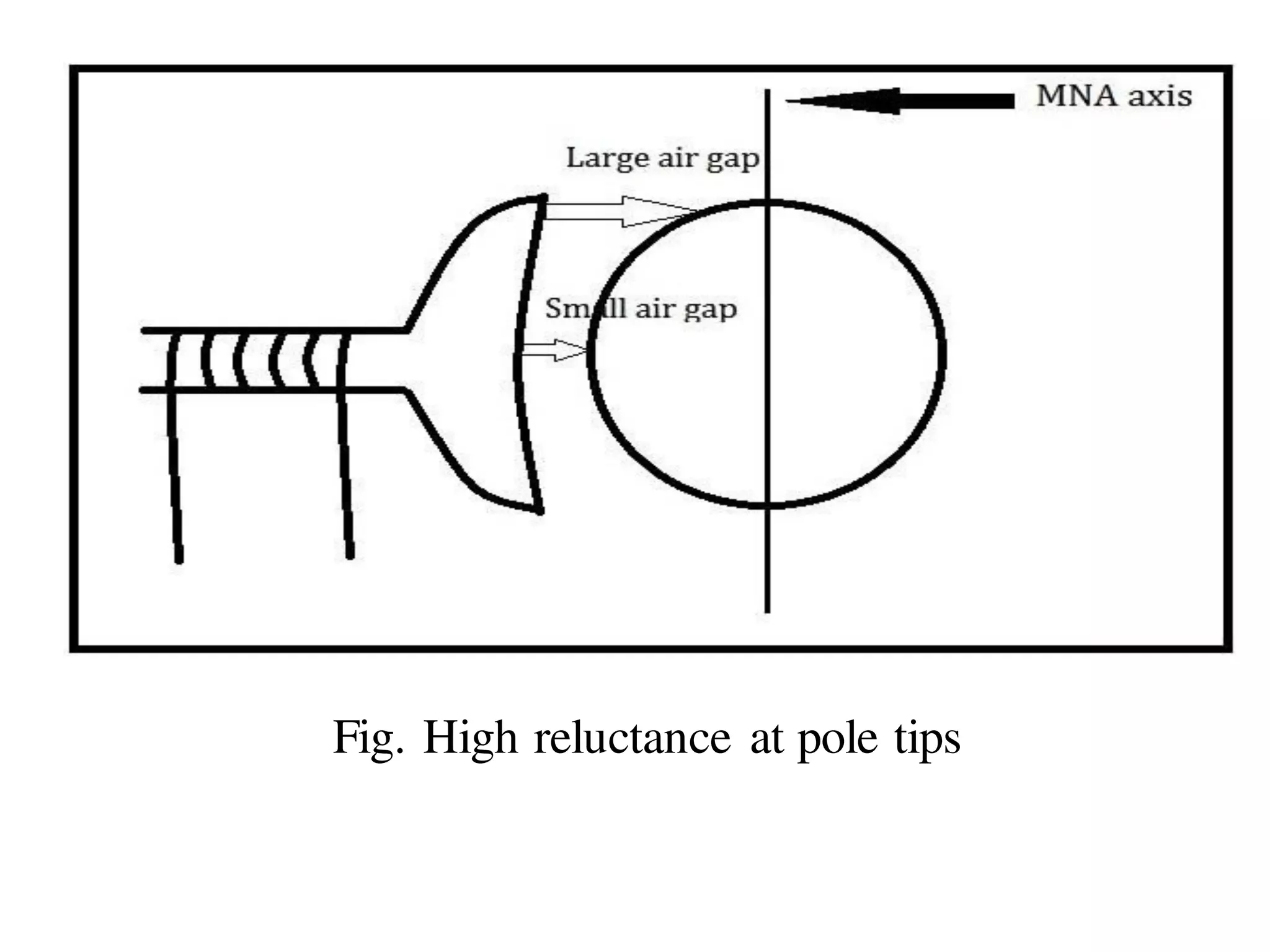
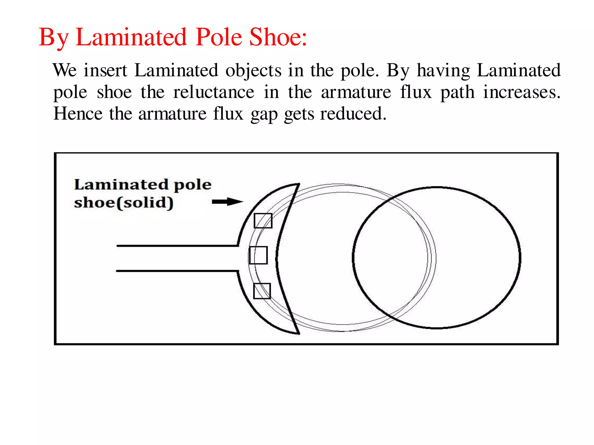
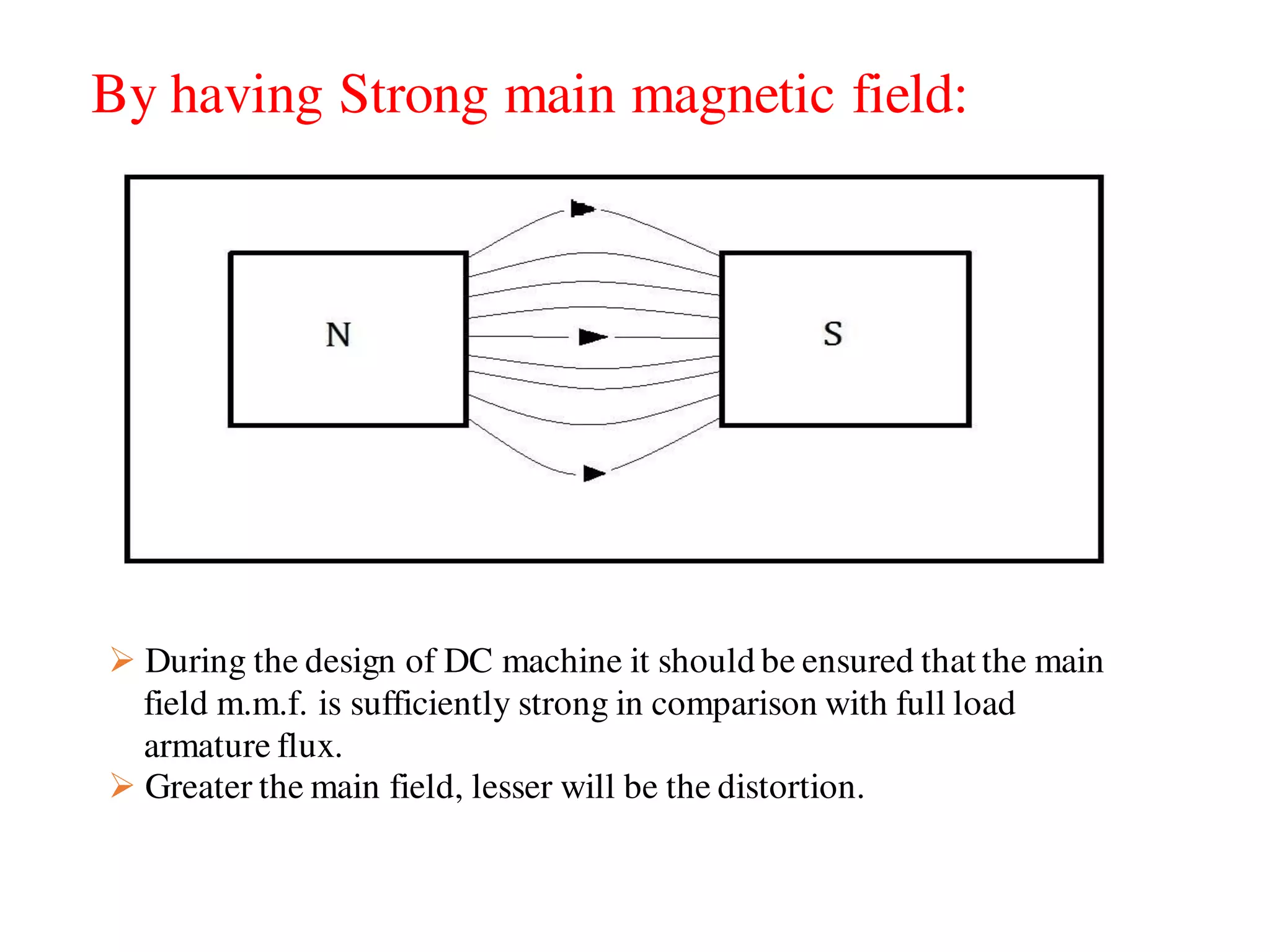
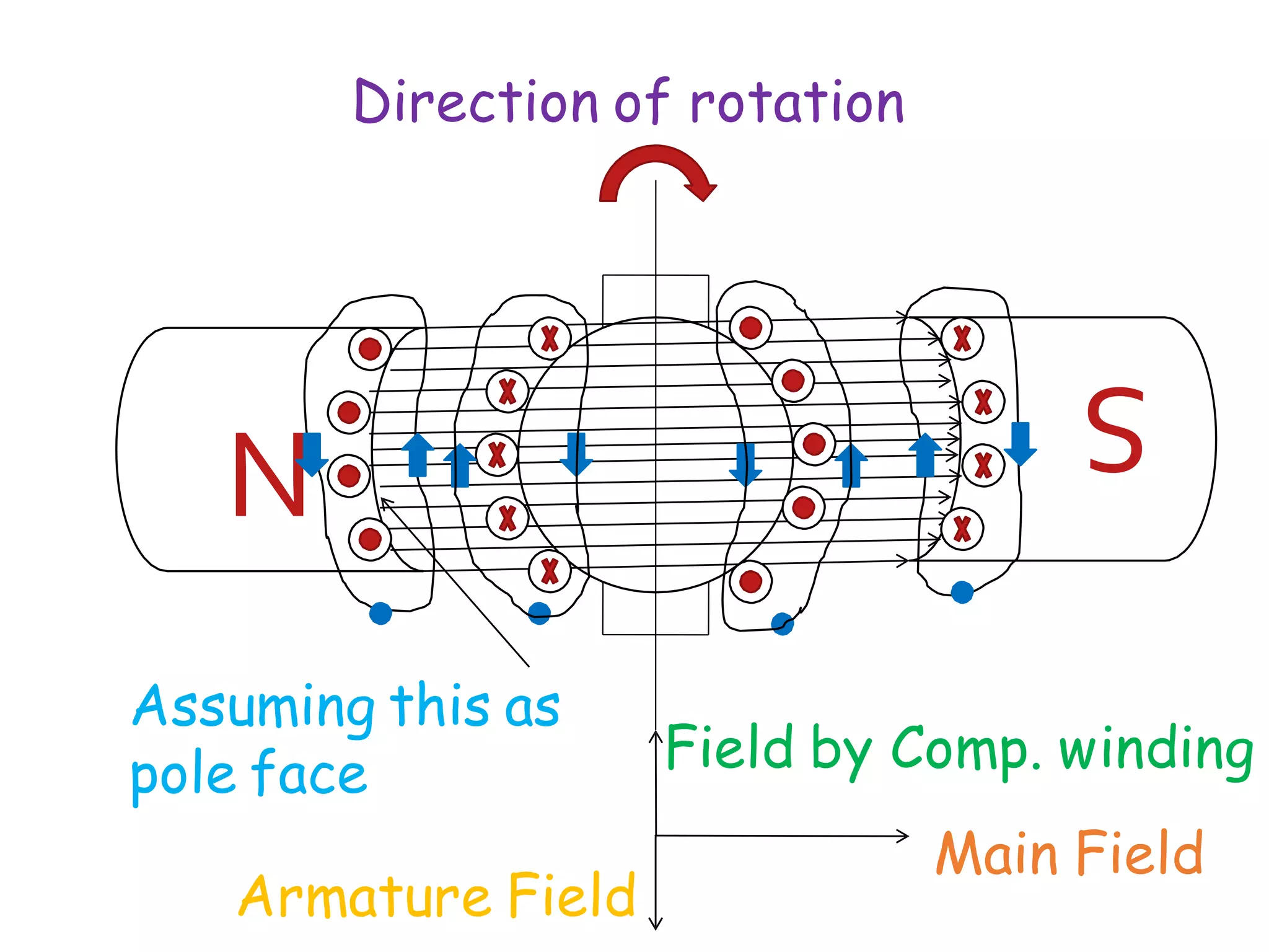
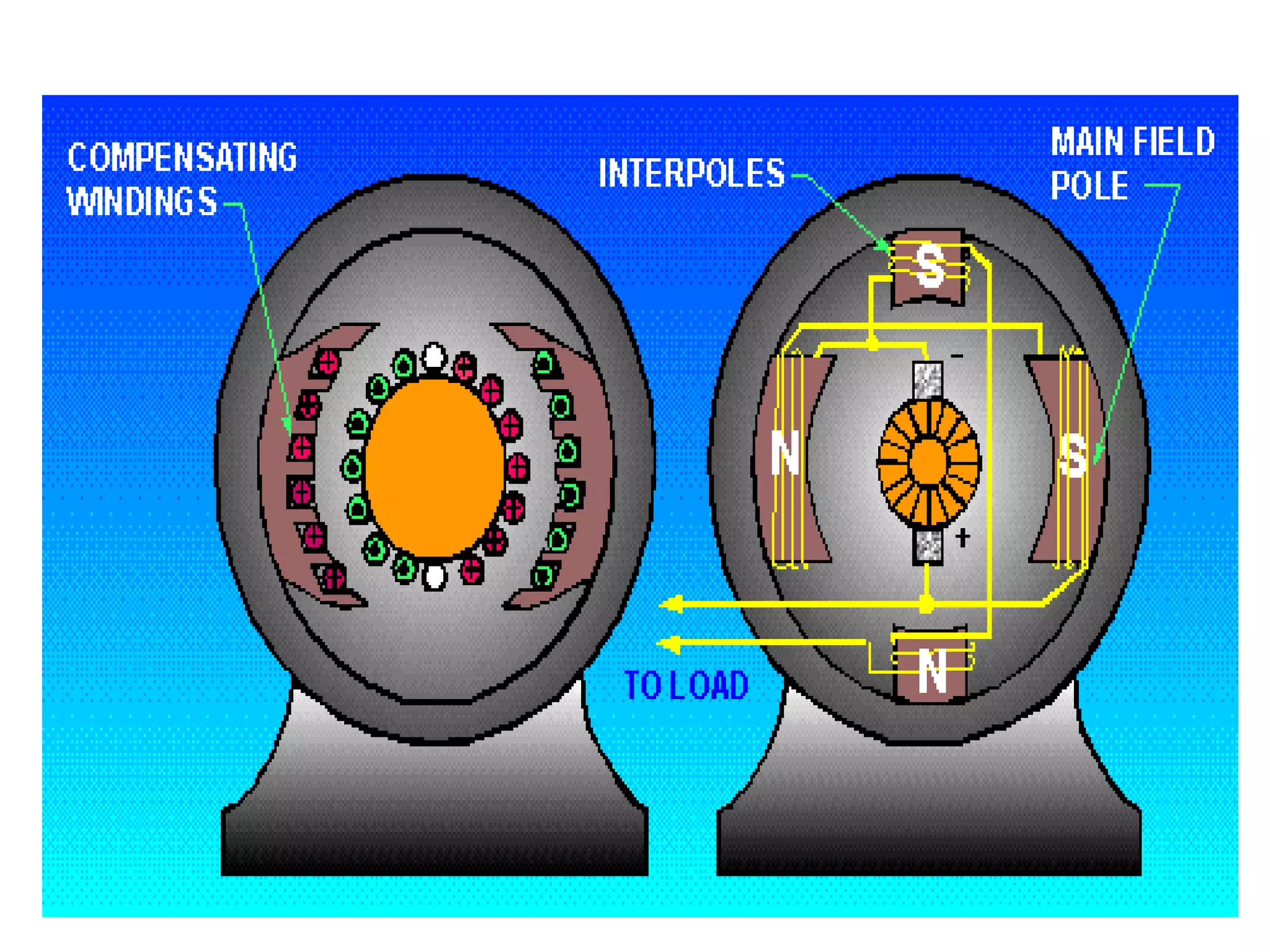
POLE
FACE
ARMATURE
YOKE
N
S
BRUSH
Armature Reaction is the
effect of “Armature Field”
on the “ main Field “.
Armature field is the field
which is produced by the
armature conductorsdue to
current flowing through
them.
Main field is the field
which is produced by the
poles which is necessary
for the operation.
DC Generator
Armature Reaction
Motion
Magnetic
Field
Current
Fleming’s Right Hand Rule
Direction of current running through conductor
N
S
q - axis
GNA
d- axis
Current
Right Hand Thumb Rule
Magnetic
Field
Magnetic
Field
Direction of Magnetic Field due to Armature Conductor Current
N
Main FieldDe-magnetizing
Cross-magnetizing
New MNAGNA
=Brush Lead
(1) De- Magnetisation
-It weakens /reduces the main flux.
(2)Cross- Magnetisation
-It distorts the main flux.
Effects Of Armature Reaction
Terminology Related To Armature Reaction
-MNA (Magnetically Neutral Axis)
It is the axis along which no E.M.F is produced, hence
brushes are kept on this axis.
-GNA (Geometrically Neutral Axis)
It is the axis which divides the armature core in two equal
parts.
-Polar Axis
It is the imaginary line which joins the center of NS poles.
Consider a two pole D.C Generator.
For the sake of simplicity, the brushes are shown directly touching
the armature conductors, but practically they touch commutator
segments.
Assume that there is no current flowing through
armature conductors, Hence..
(1)The flux is distributed symmetrically with respect
to polar axis.
(2)The M.N.A coincides the G.N.A.
Field MMF (Fm)
A
d- axis
O
Flux due to field
current alone
GNA
MNA (At no load)
Main Field Flux produced by field m.m.f at no load
d- axis
N
S
O
d- axis
Armature MMF
(Fa)
q - axis
GNA
BFlux due to
Armature
current alone
d- axis
Armature Field Flux produced by
Armature m.m.f with field unexcited
q - axis
GNA
d - axis
Fa
m
A
d-
axis
F
GNA
MNA (At on load )
O
FR
θ
Resultant of Main Field Flux and Armature Field Flux
Generator
Direction
x x x x x x
N S
Polar Axis Interpolar Axis
GNA
MNA
Polar AxisMotor
Direction
Bm Fa
Ba
ϕ
Flux distribution and Flux waveforms due to Field and
Armature currents
ϕm
ϕa
Peaky
wave
Mmf
& B
Resultant Flux waveform
ϕ
Demagnetizing and Cross-magnetizing Conductors:
Calculation of Cross-magnetizing Amp-Turns
Methods to reduce Armature Reaction
By high Reluctanceat POLE TIPS:
 At the time of constructionwe use chamfered poles.
 These poleshave larger air gap on the tips and smaller air gap at the
centre.
 These polesprovide non-uniformair gap.
 The effect of armature reaction is more near to edge of poles and
negligible near the centre of pole.
 If air gap is kept non uniform i.e., larger air gap at the edges(Pole Tip)
and smaller near the centre of the poleand then armature flux near the
pole tip decreases and armature reaction decreases.
Fig. High reluctance at pole tips
By Laminated Pole Shoe:
We insert Laminated objects in the pole. By having Laminated
pole shoe the reluctance in the armature flux path increases.
Hence the armature flux gap gets reduced.
By Reduction in Armature flux:
 The effect of Armature Reaction is reduced by creating more
reluctance in the path of Armature flux.
 This is achieved by using field Pole Laminations having several
Rectangular holes punched in them.
 It gives high Reluctance in the path of armature flux.
 Due to this armature cross flux reduces whereas main field
remains almost unaffected.
By having Strong main magnetic field:
 During the design of DC machine it should be ensured that the main
field m.m.f. is sufficiently strong in comparison with full load
armature flux.
 Greater the main field, lesser will be the distortion.
Compensating Winding:
 Compensating windings are used to nullify the cross-
magnetizing effect.
 These windings are kept in slots of pole faces.
 It carries current in opposite direction to the current of
armature winding just below the pole faces.
 It is connected in series with the armature winding.
N
Direction of rotation
Assuming this as
pole face
Main Field
Armature Field
Field by Comp. winding
Reduction methods of armature reaction in DC machines

Reduction methods of armature reaction in DC machines

  • 1.
    POLE FACE ARMATURE YOKE N S BRUSH Armature Reaction isthe effect of “Armature Field” on the “ main Field “. Armature field is the field which is produced by the armature conductorsdue to current flowing through them. Main field is the field which is produced by the poles which is necessary for the operation. DC Generator Armature Reaction
  • 2.
    Motion Magnetic Field Current Fleming’s Right HandRule Direction of current running through conductor
  • 3.
    N S q - axis GNA d-axis Current Right Hand Thumb Rule Magnetic Field Magnetic Field Direction of Magnetic Field due to Armature Conductor Current
  • 4.
  • 5.
    (1) De- Magnetisation -Itweakens /reduces the main flux. (2)Cross- Magnetisation -It distorts the main flux. Effects Of Armature Reaction
  • 6.
    Terminology Related ToArmature Reaction -MNA (Magnetically Neutral Axis) It is the axis along which no E.M.F is produced, hence brushes are kept on this axis. -GNA (Geometrically Neutral Axis) It is the axis which divides the armature core in two equal parts. -Polar Axis It is the imaginary line which joins the center of NS poles.
  • 7.
    Consider a twopole D.C Generator. For the sake of simplicity, the brushes are shown directly touching the armature conductors, but practically they touch commutator segments. Assume that there is no current flowing through armature conductors, Hence.. (1)The flux is distributed symmetrically with respect to polar axis. (2)The M.N.A coincides the G.N.A.
  • 8.
    Field MMF (Fm) A d-axis O Flux due to field current alone GNA MNA (At no load) Main Field Flux produced by field m.m.f at no load d- axis
  • 9.
    N S O d- axis Armature MMF (Fa) q- axis GNA BFlux due to Armature current alone d- axis Armature Field Flux produced by Armature m.m.f with field unexcited q - axis GNA
  • 10.
    d - axis Fa m A d- axis F GNA MNA(At on load ) O FR θ Resultant of Main Field Flux and Armature Field Flux
  • 11.
    Generator Direction x x xx x x N S Polar Axis Interpolar Axis GNA MNA Polar AxisMotor Direction Bm Fa Ba ϕ Flux distribution and Flux waveforms due to Field and Armature currents ϕm ϕa
  • 12.
  • 13.
  • 15.
  • 17.
    Methods to reduceArmature Reaction By high Reluctanceat POLE TIPS:  At the time of constructionwe use chamfered poles.  These poleshave larger air gap on the tips and smaller air gap at the centre.  These polesprovide non-uniformair gap.  The effect of armature reaction is more near to edge of poles and negligible near the centre of pole.  If air gap is kept non uniform i.e., larger air gap at the edges(Pole Tip) and smaller near the centre of the poleand then armature flux near the pole tip decreases and armature reaction decreases.
  • 18.
  • 19.
    By Laminated PoleShoe: We insert Laminated objects in the pole. By having Laminated pole shoe the reluctance in the armature flux path increases. Hence the armature flux gap gets reduced.
  • 20.
    By Reduction inArmature flux:  The effect of Armature Reaction is reduced by creating more reluctance in the path of Armature flux.  This is achieved by using field Pole Laminations having several Rectangular holes punched in them.  It gives high Reluctance in the path of armature flux.  Due to this armature cross flux reduces whereas main field remains almost unaffected.
  • 21.
    By having Strongmain magnetic field:  During the design of DC machine it should be ensured that the main field m.m.f. is sufficiently strong in comparison with full load armature flux.  Greater the main field, lesser will be the distortion.
  • 22.
    Compensating Winding:  Compensatingwindings are used to nullify the cross- magnetizing effect.  These windings are kept in slots of pole faces.  It carries current in opposite direction to the current of armature winding just below the pole faces.  It is connected in series with the armature winding.
  • 23.
    N Direction of rotation Assumingthis as pole face Main Field Armature Field Field by Comp. winding