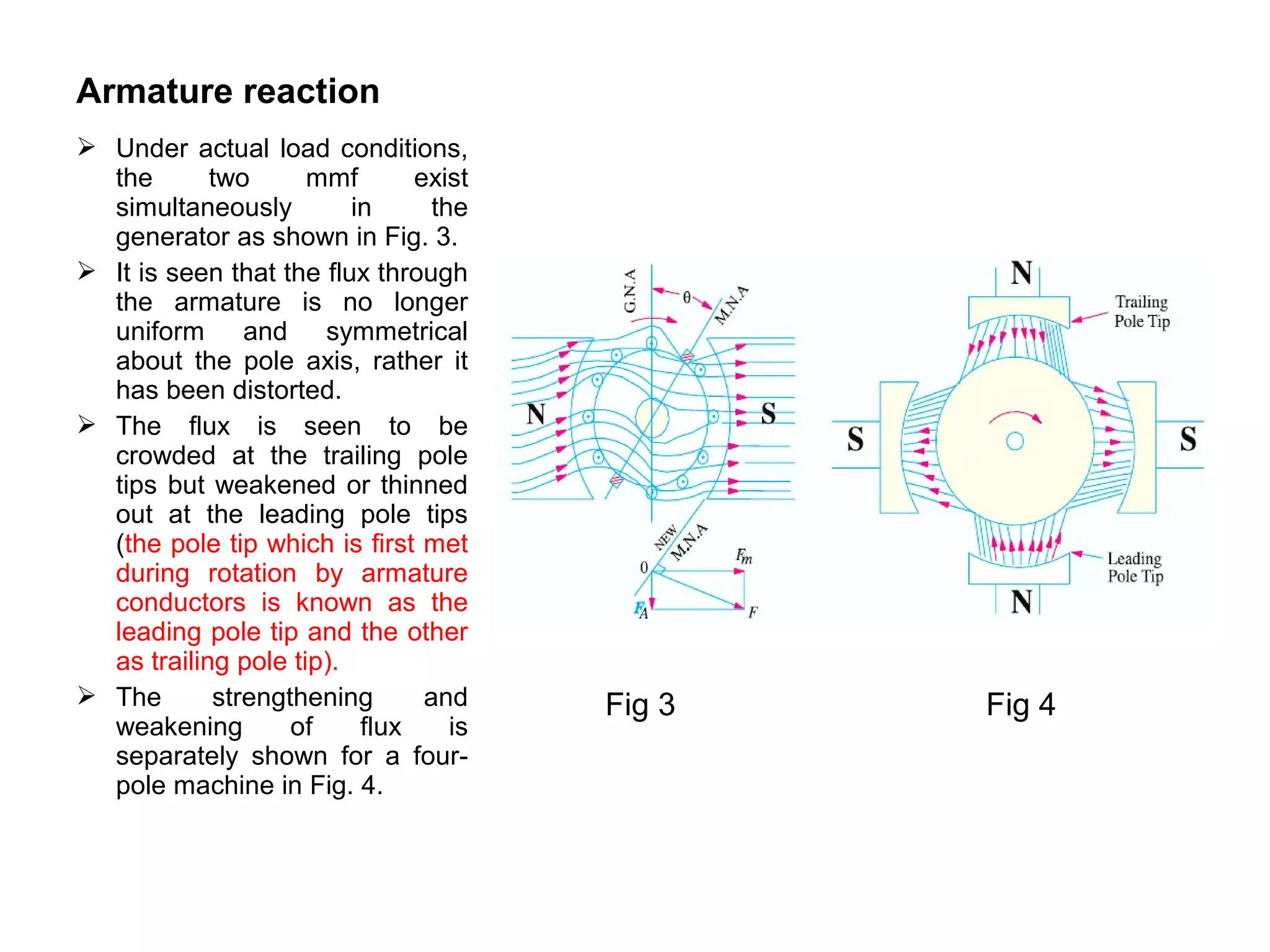
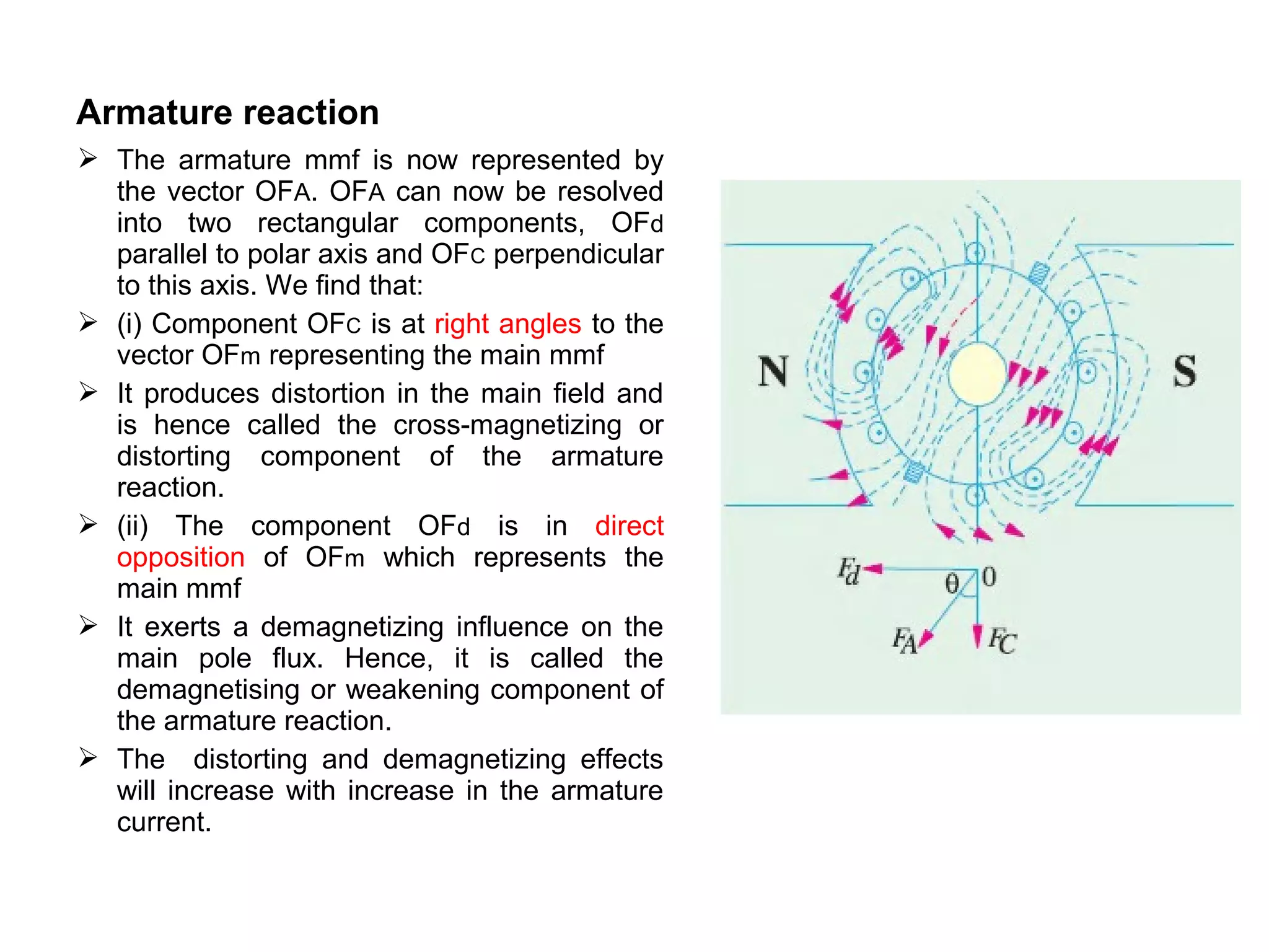
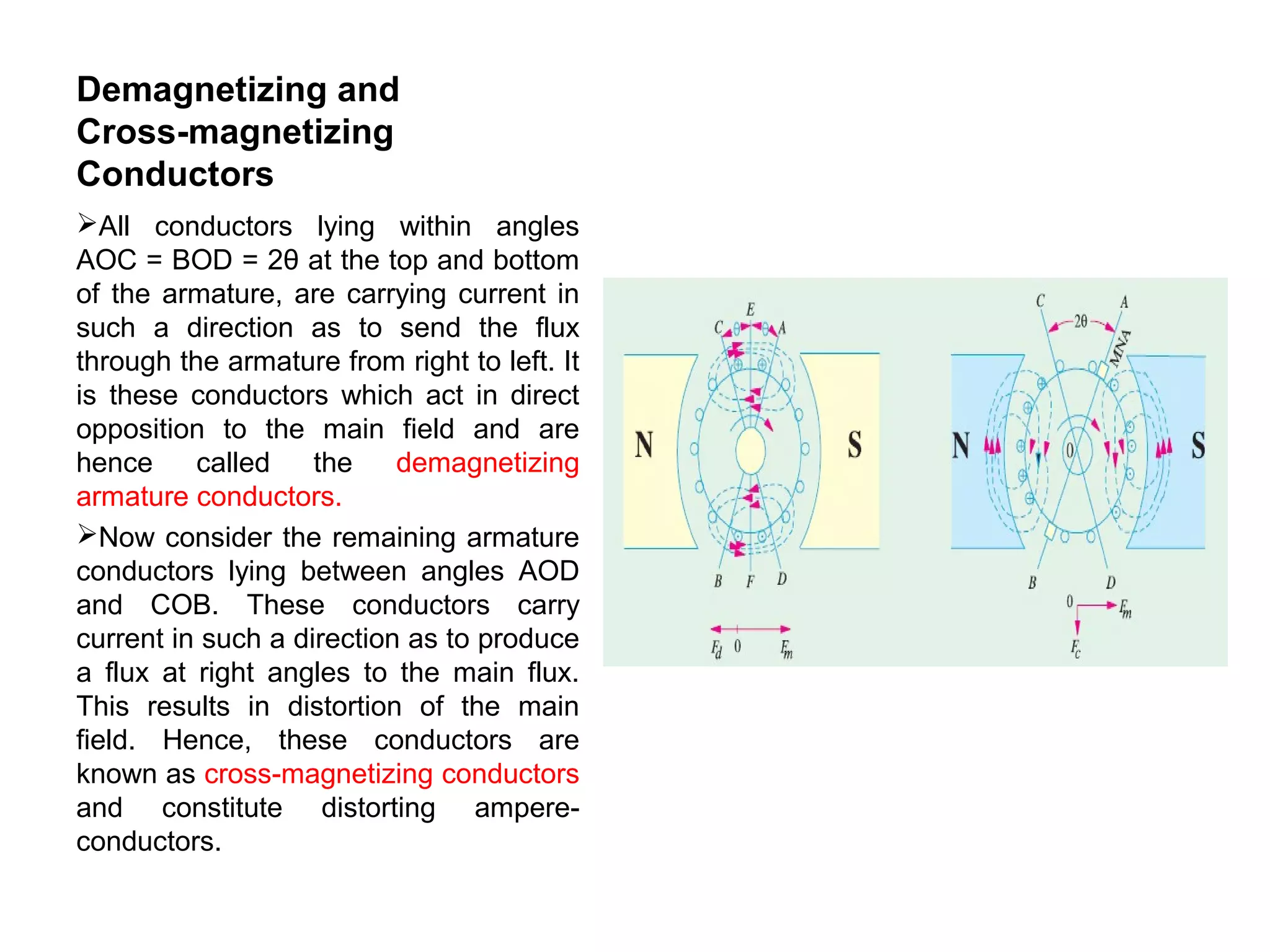
SlideShare a Scribd company logo
DC Machines
CHAPTER 2CHAPTER 2
ARMATURE REACTION AND
COMMUTATION
Armature reaction
• Armature reaction: The effect of magnetic field set up by armature
current on the distribution of flux under main poles of a dc machine.
The armature magnetic field has two effects:
• (i) It demagnetizes or weakens the main flux and
• (ii) It cross-magnetizes or distorts it
Polar axis and MNA
Polar axis: The flux is distributed
symmetrically with respect to polar axis,
which is the line joining the centers of NS
poles.
Magnetic neutral axis:
The magnetic neutral axis(MNA) or plane
coincides with the geometrical neutral axis or
plane. It is the axis along which no emf is
induced in the armature conductors because
they then move in parallel with the lines of
flux.
Therefore the brushes are placed along
MNA. Hence, MNA is called the axis of
commutation because of the reversal of
current in armature conductors takes place
across this axis. M.N.A. is the axis which is
perpendicular to the flux passing through the
armature
Fig1.Main magnetic field
Fig2.Armature magnetic
field
 As seen from Fig 1, Vector OFm
represents, both magnitude and
direction, of the mmf producing the
main flux.
 Fig 2 shows the field (or flux) set up
by the armature conductors alone
when carrying current, the field coils
being unexcited.
 The current direction is downwards in
conductors under N-pole and
upwards in those under S-pole.
 The armature mmf (depending on the
strength of the armature current) is
shown separately both in magnitude
and direction by the vector OFA.
Fig1.Main magnetic field
Fig2.Armature magnetic
field
Armature reaction
 Under actual load conditions,
the two mmf exist
simultaneously in the
generator as shown in Fig. 3.
 It is seen that the flux through
the armature is no longer
uniform and symmetrical
about the pole axis, rather it
has been distorted.
 The flux is seen to be
crowded at the trailing pole
tips but weakened or thinned
out at the leading pole tips
(the pole tip which is first met
during rotation by armature
conductors is known as the
leading pole tip and the other
as trailing pole tip).
 The strengthening and
weakening of flux is
separately shown for a four-
pole machine in Fig. 4.
Fig 3 Fig 4
Armature reaction
 In Fig.3 is shown the resultant mmf
OF which is found by vectorially
combining OFm and OFA. And the
new position of M.N.A which is always
perpendicular to the resultant mmf
vector OF, is also shown in the figure.
With the shift of M.N.A. So, through
an angle θ brushes are also shifted so
as to lie along the new position of
M.N.A.
 Due to this brush shift , the armature
conductors and hence armature
current is redistributed. All conductors
to the left of new position of M.N.A.
but between the two brushes, carry
current downwards and those to the
right carry current upwards. The
armature mmf is found to lie in the
direction of the new position of M.N.A.
(or brush axis).
Armature reaction
 The armature mmf is now represented by
the vector OFA. OFA can now be resolved
into two rectangular components, OFd
parallel to polar axis and OFC perpendicular
to this axis. We find that:
 (i) Component OFC is at right angles to the
vector OFm representing the main mmf
 It produces distortion in the main field and
is hence called the cross-magnetizing or
distorting component of the armature
reaction.
 (ii) The component OFd is in direct
opposition of OFm which represents the
main mmf
 It exerts a demagnetizing influence on the
main pole flux. Hence, it is called the
demagnetising or weakening component of
the armature reaction.
 The distorting and demagnetizing effects
will increase with increase in the armature
current.
Demagnetizing and
Cross-magnetizing
Conductors
All conductors lying within angles
AOC = BOD = 2θ at the top and bottom
of the armature, are carrying current in
such a direction as to send the flux
through the armature from right to left. It
is these conductors which act in direct
opposition to the main field and are
hence called the demagnetizing
armature conductors.
Now consider the remaining armature
conductors lying between angles AOD
and COB. These conductors carry
current in such a direction as to produce
a flux at right angles to the main flux.
This results in distortion of the main
field. Hence, these conductors are
known as cross-magnetizing conductors
and constitute distorting ampere-
conductors.
Solution for Cross-
magnetizing and
Demagnetizing effect
The armature demagnetizing
ampere-turns are neutralized
by adding extra ampere-turns
to the main field winding.
Compensating windings are
used for nullifying the cross
magnetization effect. These
windings are embedded in
slots in the pole shoes and are
connected in series with
armature in such a way that
the current in them flows in
opposite direction to that
flowing in armature conductors
directly below the pole shoes.
Commutation
A,B,C represent the three coils of
armature. a,b,c are the
Commutator segments.
The brush width is equal to width
of one Commutator segments and
one mica insulation.
In the figure it can be seen that
Commutator is moving in such a
way that the brush first touches
Commutator segment b and then
segment a.
From figure(a) it can be seen that
each coil is carrying 20 A. Brush is
connected to segment b. Thus
brush current is 40 A.
Prior to short-circuit the coil B
belongs to the group of coils lying
to the left of brush.
As seen from figure(b) coil B has
entered the short-circuit period and
has reached 1/3 of period.
Commutation
So the current through coil B has
been reduced from 20 A to 10 A, the
other 10 A is flowing from segment a.
In figure(c) it can be seen that the
coil is short-circuited and current
through it is zero.
Figure(d) shows that the coil has
become a part of the coils lying to the
right of brush. It can be seen that the
brush contact area with segment a is
increased as compared to that with
segment b.
Coil B now carries 10 A but in
reverse direction.
Figure(e) shows that the brush is not
touching segment b and coil B carries
15 A, while 5A directly jumps through
air to segment a causing sparking.
Reactance voltage
 So, it can be concluded that sparking at the brushes, which results in poor
commutation is due to the inability of the current in the short-circuited coil to reverse
completely by the end of short-circuit period (which is usually of the order of 1/500
second).
 The main cause which retards or delays this quick reversal is the production of self-
induced emf in the coil undergoing commutation.
 It may be pointed out that the coil possesses appreciable amount of self inductance
because it lies embedded in a material of high magnetic permeability. This self-
induced emf is known as reactance voltage.
 The value of reactance voltage= co-efficient of self-inductance × rate of change of
current
 Time of short circuit or commutation is the time required for the Commutator to move
a distance equal to circumferential thickness of brush(Wb) minus the thickness of one
insulating plate of strip of mica(Wm).
 Tc = (Wb-Wm)/v
 v=peripheral velocity of Commutator segments in cm/second
 If I is the current through one conductor than 2I is current through conductor during
short circuit period.
 Therefore reactance voltage = L × (2I/ Tc)(for linear commuation)
 reactance voltage =1.11L × (2I/ Tc)(for sinusoidal commuation)
Methods of Improving Commutation
There are two practical ways of improving commutation i.e. of
making current reversal in the short-circuited coil as spark less as
possible. These methods are known as
 (i) resistance commutation and
 (ii) emf. Commutation
Resistance Commutation:
This method of improving commutation consists of replacing
low-resistance Cu brushes by comparatively high-resistance
carbon brushes.
If copper brushes are used then since they have low resistance
some current passes through bar b and more current passes
through bar a.
But if high resistance carbon brushes are used, then the current
will prefer going through bar a, as (i) the resistance r1 of the first
path will increase due to diminishing area of contact of bar ‘b’ with
brush and because
(ii) Resistance r2 of second path will decrease due to rapidly
increasing contact area of bar ‘a’ with the brush.
Disadvantage of carbon brush:
Due to their high contact resistance (which is beneficial to
sparkless commutation) a loss of approximately 2 volt is caused.
E.M.F commutation
In this method, arrangement is made to
neutralize the reactance voltage by
producing a reversing emf in the short-
circuited coil under commutation.
This reversing emf, as the name shows,
is an emf in opposition to the reactance
voltage and if its value is made equal to
the latter, it will completely wipe it off,
thereby producing quick reversal of
current in the short-circuited coil which
will result in spark less commutation. The
reversing emf may be produced in two
ways:
 (i) either by giving the brushes a
forward lead sufficient enough to bring the
short-circuited coil under the influence of
next pole of opposite polarity
 (ii) by using interpoles.
Interpoles of Compoles
These are small poles fixed to the yoke and spaced in
between the main poles. They are wound with
comparatively few heavy gauge Cu wire turns and are
connected in series with the armature so that they carry full
armature current. Their polarity, in the case of a generator,
is the same as that of the main pole ahead in the direction
of rotation. The function of interpoles is two-fold:
(i) As their polarity is the same as that of the main pole
ahead, they induce an emf in the coil (under commutation)
which helps the reversal of current. The emf induced by the
compoles is known as commutating or reversing emf. The
commutating emf neutralizes the reactance emf thereby
making commutation spark less. With interpoles, spark less
commutation can be obtained up to 20 % to 30% overload
with fixed brush position.
(ii)Another function of the interpoles is to neutralize the
cross-magnetizing effect of armature reaction. Hence,
brushes are not to be shifted from the original position.

More Related Content

What's hot

Chapter 2
Chapter 2Chapter 2
Chapter 2
Yimam Alemu
 
Sag and tension
Sag and tensionSag and tension
Sag and tension
rajendrachoudhary123
 
Armature reaction
Armature reactionArmature reaction
Armature reaction
Dinesh Sharma
 
ABCB(air blast circuit breaker)
ABCB(air blast circuit breaker)ABCB(air blast circuit breaker)
ABCB(air blast circuit breaker)
AB Amit
 
Two reaction theory and slip test
Two reaction theory and slip testTwo reaction theory and slip test
Two reaction theory and slip test
karthi1017
 
moving iron instrument
 moving iron instrument moving iron instrument
moving iron instrument
ezhilsubitham
 
Synchronous generator construction
Synchronous generator constructionSynchronous generator construction
Synchronous generator construction
AnilKumarJain19
 
Transformer : Equivalent Circuit
Transformer : Equivalent CircuitTransformer : Equivalent Circuit
Transformer : Equivalent Circuit
Muhammad Ridwanul Hoque
 
Basics of Electrical Machines
Basics of Electrical MachinesBasics of Electrical Machines
Basics of Electrical Machines
maneesh001
 
Pmmc instrument
Pmmc instrumentPmmc instrument
Pmmc instrument
GITAM UNIVERSITY
 
Per unit system
Per unit systemPer unit system
Per unit system
Muhammad Kamran Shaikh
 
Armature reaction
Armature reactionArmature reaction
Armature reaction
SidHeart Sharma
 
dc Generator Ppt
dc Generator Pptdc Generator Ppt
dc Generator Ppt
kiit university
 
Symmetrical and un-symmetrical fault
Symmetrical and un-symmetrical faultSymmetrical and un-symmetrical fault
Symmetrical and un-symmetrical fault
siddiqui arshad hussain
 
Dc machines (Generator & Motor)
Dc machines (Generator & Motor)Dc machines (Generator & Motor)
Dc machines (Generator & Motor)
Mohammed Waris Senan
 
DC Generator.ppt
DC Generator.pptDC Generator.ppt
DC Generator.ppt
AjayKumar4724
 
Notes on armature reaction in dc machines
Notes on armature reaction in dc machinesNotes on armature reaction in dc machines
Notes on armature reaction in dc machines
Mohammad Umar Rehman
 
Transformer
TransformerTransformer
Electric machine
Electric machineElectric machine
Electric machine
ashok261084
 
Dc motor
Dc motorDc motor
Dc motor
Kishan
 

What's hot (20)

Chapter 2
Chapter 2Chapter 2
Chapter 2
 
Sag and tension
Sag and tensionSag and tension
Sag and tension
 
Armature reaction
Armature reactionArmature reaction
Armature reaction
 
ABCB(air blast circuit breaker)
ABCB(air blast circuit breaker)ABCB(air blast circuit breaker)
ABCB(air blast circuit breaker)
 
Two reaction theory and slip test
Two reaction theory and slip testTwo reaction theory and slip test
Two reaction theory and slip test
 
moving iron instrument
 moving iron instrument moving iron instrument
moving iron instrument
 
Synchronous generator construction
Synchronous generator constructionSynchronous generator construction
Synchronous generator construction
 
Transformer : Equivalent Circuit
Transformer : Equivalent CircuitTransformer : Equivalent Circuit
Transformer : Equivalent Circuit
 
Basics of Electrical Machines
Basics of Electrical MachinesBasics of Electrical Machines
Basics of Electrical Machines
 
Pmmc instrument
Pmmc instrumentPmmc instrument
Pmmc instrument
 
Per unit system
Per unit systemPer unit system
Per unit system
 
Armature reaction
Armature reactionArmature reaction
Armature reaction
 
dc Generator Ppt
dc Generator Pptdc Generator Ppt
dc Generator Ppt
 
Symmetrical and un-symmetrical fault
Symmetrical and un-symmetrical faultSymmetrical and un-symmetrical fault
Symmetrical and un-symmetrical fault
 
Dc machines (Generator & Motor)
Dc machines (Generator & Motor)Dc machines (Generator & Motor)
Dc machines (Generator & Motor)
 
DC Generator.ppt
DC Generator.pptDC Generator.ppt
DC Generator.ppt
 
Notes on armature reaction in dc machines
Notes on armature reaction in dc machinesNotes on armature reaction in dc machines
Notes on armature reaction in dc machines
 
Transformer
TransformerTransformer
Transformer
 
Electric machine
Electric machineElectric machine
Electric machine
 
Dc motor
Dc motorDc motor
Dc motor
 

Viewers also liked

Armature Reaction
Armature Reaction Armature Reaction
Armature Reaction
GPERI
 
Armature Reaction
Armature ReactionArmature Reaction
Armature Reaction
Vishal Thakur
 
Me3202 Engineering Design For Product
Me3202 Engineering Design For ProductMe3202 Engineering Design For Product
Me3202 Engineering Design For Product
Anthony Chan
 
Amit seth armature_reaction[1]
Amit seth armature_reaction[1]Amit seth armature_reaction[1]
Amit seth armature_reaction[1]
sethamit
 
Emc510 s emec_lect_notes_sem-1_2016_lecture-2
Emc510 s emec_lect_notes_sem-1_2016_lecture-2Emc510 s emec_lect_notes_sem-1_2016_lecture-2
Emc510 s emec_lect_notes_sem-1_2016_lecture-2
Timoteus Ikaku
 
Earthquake Waves
Earthquake WavesEarthquake Waves
Earthquake Waves
twindsor1
 
SWR
SWRSWR
(Slides) Efficient Evaluation Methods of Elementary Functions Suitable for SI...
(Slides) Efficient Evaluation Methods of Elementary Functions Suitable for SI...(Slides) Efficient Evaluation Methods of Elementary Functions Suitable for SI...
(Slides) Efficient Evaluation Methods of Elementary Functions Suitable for SI...
Naoki Shibata
 
Microwave engineering ch2
Microwave engineering ch2Microwave engineering ch2
Microwave engineering ch2
Muhammad Azwir
 
Introduction to Finite Elements
Introduction to Finite ElementsIntroduction to Finite Elements
Introduction to Finite Elements
Srinivas Varanasi, Ph.D.
 
space vector PWM for 2 leg inverter
space vector PWM for 2 leg inverterspace vector PWM for 2 leg inverter
space vector PWM for 2 leg inverter
Sudhakar Reddy
 
Finete Element
Finete ElementFinete Element
Finete Element
Fabian Manoppo
 
Sinusoidal PWM and Space Vector Modulation For Two Level Voltage Source Conve...
Sinusoidal PWM and Space Vector Modulation For Two Level Voltage Source Conve...Sinusoidal PWM and Space Vector Modulation For Two Level Voltage Source Conve...
Sinusoidal PWM and Space Vector Modulation For Two Level Voltage Source Conve...
ZunAib Ali
 
GENERATING OF HIGH ALTERNATING VOLTAGE
GENERATING OF HIGH ALTERNATING VOLTAGEGENERATING OF HIGH ALTERNATING VOLTAGE
GENERATING OF HIGH ALTERNATING VOLTAGE
Jamil Abdullah
 
Space vector PWM
Space vector PWMSpace vector PWM
Space vector PWM
Long Thang Pham
 
Transmission Media
Transmission MediaTransmission Media
Transmission Media
Sourav Roy
 
Hv chap8
Hv chap8Hv chap8
Ppt for tranmission media
Ppt for tranmission mediaPpt for tranmission media
Ppt for tranmission media
Manish8976
 
DATA STRUCTURES
DATA STRUCTURESDATA STRUCTURES
DATA STRUCTURES
bca2010
 

Viewers also liked (19)

Armature Reaction
Armature Reaction Armature Reaction
Armature Reaction
 
Armature Reaction
Armature ReactionArmature Reaction
Armature Reaction
 
Me3202 Engineering Design For Product
Me3202 Engineering Design For ProductMe3202 Engineering Design For Product
Me3202 Engineering Design For Product
 
Amit seth armature_reaction[1]
Amit seth armature_reaction[1]Amit seth armature_reaction[1]
Amit seth armature_reaction[1]
 
Emc510 s emec_lect_notes_sem-1_2016_lecture-2
Emc510 s emec_lect_notes_sem-1_2016_lecture-2Emc510 s emec_lect_notes_sem-1_2016_lecture-2
Emc510 s emec_lect_notes_sem-1_2016_lecture-2
 
Earthquake Waves
Earthquake WavesEarthquake Waves
Earthquake Waves
 
SWR
SWRSWR
SWR
 
(Slides) Efficient Evaluation Methods of Elementary Functions Suitable for SI...
(Slides) Efficient Evaluation Methods of Elementary Functions Suitable for SI...(Slides) Efficient Evaluation Methods of Elementary Functions Suitable for SI...
(Slides) Efficient Evaluation Methods of Elementary Functions Suitable for SI...
 
Microwave engineering ch2
Microwave engineering ch2Microwave engineering ch2
Microwave engineering ch2
 
Introduction to Finite Elements
Introduction to Finite ElementsIntroduction to Finite Elements
Introduction to Finite Elements
 
space vector PWM for 2 leg inverter
space vector PWM for 2 leg inverterspace vector PWM for 2 leg inverter
space vector PWM for 2 leg inverter
 
Finete Element
Finete ElementFinete Element
Finete Element
 
Sinusoidal PWM and Space Vector Modulation For Two Level Voltage Source Conve...
Sinusoidal PWM and Space Vector Modulation For Two Level Voltage Source Conve...Sinusoidal PWM and Space Vector Modulation For Two Level Voltage Source Conve...
Sinusoidal PWM and Space Vector Modulation For Two Level Voltage Source Conve...
 
GENERATING OF HIGH ALTERNATING VOLTAGE
GENERATING OF HIGH ALTERNATING VOLTAGEGENERATING OF HIGH ALTERNATING VOLTAGE
GENERATING OF HIGH ALTERNATING VOLTAGE
 
Space vector PWM
Space vector PWMSpace vector PWM
Space vector PWM
 
Transmission Media
Transmission MediaTransmission Media
Transmission Media
 
Hv chap8
Hv chap8Hv chap8
Hv chap8
 
Ppt for tranmission media
Ppt for tranmission mediaPpt for tranmission media
Ppt for tranmission media
 
DATA STRUCTURES
DATA STRUCTURESDATA STRUCTURES
DATA STRUCTURES
 

Similar to Armaturereaction&commutation

Dc generator
Dc generatorDc generator
Dc generator
MEHTA NIRAV
 
LOW CONVERSION LOSS DUAL GENERATOR
LOW CONVERSION LOSS DUAL GENERATORLOW CONVERSION LOSS DUAL GENERATOR
LOW CONVERSION LOSS DUAL GENERATOR
Journal For Research
 
Armature reaction
Armature reactionArmature reaction
Armature reaction
Prashant Menghal
 
DC machine.ppt
DC machine.pptDC machine.ppt
DC machine.ppt
LAYTH3
 
RGPV DIPLOMA EX305 UNIT II
RGPV DIPLOMA EX305 UNIT IIRGPV DIPLOMA EX305 UNIT II
RGPV DIPLOMA EX305 UNIT II
Mani Deep Dutt
 
2465716.ppt
2465716.ppt2465716.ppt
BE8251 AGRI 24may.pptx
BE8251 AGRI 24may.pptxBE8251 AGRI 24may.pptx
BE8251 AGRI 24may.pptx
MalathyN5
 
Transformer wikipedia, the free encyclopedia
Transformer   wikipedia, the free encyclopediaTransformer   wikipedia, the free encyclopedia
Transformer wikipedia, the free encyclopedia
Bibek Chouhan
 
Transformer wikipedia, the free encyclopedia
Transformer   wikipedia, the free encyclopediaTransformer   wikipedia, the free encyclopedia
Transformer wikipedia, the free encyclopedia
Bibek Chouhan
 
RGPV Unit i ex503 - copy
RGPV Unit i ex503 - copyRGPV Unit i ex503 - copy
RGPV Unit i ex503 - copy
Mani Deep Dutt
 
DC GENERATORS-BEEE.pptx
DC GENERATORS-BEEE.pptxDC GENERATORS-BEEE.pptx
DC GENERATORS-BEEE.pptx
BhumaNagaPavan
 
Generation of A.C. voltage
Generation of A.C. voltageGeneration of A.C. voltage
Generation of A.C. voltage
GPERI
 
Chapter 5 electromagnetism
Chapter 5   electromagnetismChapter 5   electromagnetism
Chapter 5 electromagnetism
Aca Jafri
 
Generator ppt 1
Generator ppt 1Generator ppt 1
Generator ppt 1
BrijeshPrasad13
 
electromagnetism Exam coverage.pptx
electromagnetism Exam coverage.pptxelectromagnetism Exam coverage.pptx
electromagnetism Exam coverage.pptx
WalidHassan53
 
Transformers
TransformersTransformers
Transformers
mrmeredith
 
[L2 Sambhav] Electro magnetic induction.pdf
[L2 Sambhav] Electro magnetic induction.pdf[L2 Sambhav] Electro magnetic induction.pdf
[L2 Sambhav] Electro magnetic induction.pdf
SaptakPaul
 
Voltmeter & Transformers: Types and Applications.
Voltmeter & Transformers: Types and  Applications.Voltmeter & Transformers: Types and  Applications.
Voltmeter & Transformers: Types and Applications.
Diksha Prakash
 
Electromagnetic induction
Electromagnetic inductionElectromagnetic induction
Electromagnetic induction
naomizammit2003
 
Full transformer
Full transformerFull transformer
Full transformer
Prateek Anandpara
 

Similar to Armaturereaction&commutation (20)

Dc generator
Dc generatorDc generator
Dc generator
 
LOW CONVERSION LOSS DUAL GENERATOR
LOW CONVERSION LOSS DUAL GENERATORLOW CONVERSION LOSS DUAL GENERATOR
LOW CONVERSION LOSS DUAL GENERATOR
 
Armature reaction
Armature reactionArmature reaction
Armature reaction
 
DC machine.ppt
DC machine.pptDC machine.ppt
DC machine.ppt
 
RGPV DIPLOMA EX305 UNIT II
RGPV DIPLOMA EX305 UNIT IIRGPV DIPLOMA EX305 UNIT II
RGPV DIPLOMA EX305 UNIT II
 
2465716.ppt
2465716.ppt2465716.ppt
2465716.ppt
 
BE8251 AGRI 24may.pptx
BE8251 AGRI 24may.pptxBE8251 AGRI 24may.pptx
BE8251 AGRI 24may.pptx
 
Transformer wikipedia, the free encyclopedia
Transformer   wikipedia, the free encyclopediaTransformer   wikipedia, the free encyclopedia
Transformer wikipedia, the free encyclopedia
 
Transformer wikipedia, the free encyclopedia
Transformer   wikipedia, the free encyclopediaTransformer   wikipedia, the free encyclopedia
Transformer wikipedia, the free encyclopedia
 
RGPV Unit i ex503 - copy
RGPV Unit i ex503 - copyRGPV Unit i ex503 - copy
RGPV Unit i ex503 - copy
 
DC GENERATORS-BEEE.pptx
DC GENERATORS-BEEE.pptxDC GENERATORS-BEEE.pptx
DC GENERATORS-BEEE.pptx
 
Generation of A.C. voltage
Generation of A.C. voltageGeneration of A.C. voltage
Generation of A.C. voltage
 
Chapter 5 electromagnetism
Chapter 5   electromagnetismChapter 5   electromagnetism
Chapter 5 electromagnetism
 
Generator ppt 1
Generator ppt 1Generator ppt 1
Generator ppt 1
 
electromagnetism Exam coverage.pptx
electromagnetism Exam coverage.pptxelectromagnetism Exam coverage.pptx
electromagnetism Exam coverage.pptx
 
Transformers
TransformersTransformers
Transformers
 
[L2 Sambhav] Electro magnetic induction.pdf
[L2 Sambhav] Electro magnetic induction.pdf[L2 Sambhav] Electro magnetic induction.pdf
[L2 Sambhav] Electro magnetic induction.pdf
 
Voltmeter & Transformers: Types and Applications.
Voltmeter & Transformers: Types and  Applications.Voltmeter & Transformers: Types and  Applications.
Voltmeter & Transformers: Types and Applications.
 
Electromagnetic induction
Electromagnetic inductionElectromagnetic induction
Electromagnetic induction
 
Full transformer
Full transformerFull transformer
Full transformer
 

Recently uploaded

OOPS_Lab_Manual - programs using C++ programming language
OOPS_Lab_Manual - programs using C++ programming languageOOPS_Lab_Manual - programs using C++ programming language
OOPS_Lab_Manual - programs using C++ programming language
PreethaV16
 
Asymmetrical Repulsion Magnet Motor Ratio 6-7.pdf
Asymmetrical Repulsion Magnet Motor Ratio 6-7.pdfAsymmetrical Repulsion Magnet Motor Ratio 6-7.pdf
Asymmetrical Repulsion Magnet Motor Ratio 6-7.pdf
felixwold
 
SMT process how to making and defects finding
SMT process how to making and defects findingSMT process how to making and defects finding
SMT process how to making and defects finding
rameshqapcba
 
Sri Guru Hargobind Ji - Bandi Chor Guru.pdf
Sri Guru Hargobind Ji - Bandi Chor Guru.pdfSri Guru Hargobind Ji - Bandi Chor Guru.pdf
Sri Guru Hargobind Ji - Bandi Chor Guru.pdf
Balvir Singh
 
一比一原版(爱大毕业证书)爱荷华大学毕业证如何办理
一比一原版(爱大毕业证书)爱荷华大学毕业证如何办理一比一原版(爱大毕业证书)爱荷华大学毕业证如何办理
一比一原版(爱大毕业证书)爱荷华大学毕业证如何办理
nedcocy
 
Particle Swarm Optimization–Long Short-Term Memory based Channel Estimation w...
Particle Swarm Optimization–Long Short-Term Memory based Channel Estimation w...Particle Swarm Optimization–Long Short-Term Memory based Channel Estimation w...
Particle Swarm Optimization–Long Short-Term Memory based Channel Estimation w...
IJCNCJournal
 
AN INTRODUCTION OF AI & SEARCHING TECHIQUES
AN INTRODUCTION OF AI & SEARCHING TECHIQUESAN INTRODUCTION OF AI & SEARCHING TECHIQUES
AN INTRODUCTION OF AI & SEARCHING TECHIQUES
drshikhapandey2022
 
Supermarket Management System Project Report.pdf
Supermarket Management System Project Report.pdfSupermarket Management System Project Report.pdf
Supermarket Management System Project Report.pdf
Kamal Acharya
 
Open Channel Flow: fluid flow with a free surface
Open Channel Flow: fluid flow with a free surfaceOpen Channel Flow: fluid flow with a free surface
Open Channel Flow: fluid flow with a free surface
Indrajeet sahu
 
Prediction of Electrical Energy Efficiency Using Information on Consumer's Ac...
Prediction of Electrical Energy Efficiency Using Information on Consumer's Ac...Prediction of Electrical Energy Efficiency Using Information on Consumer's Ac...
Prediction of Electrical Energy Efficiency Using Information on Consumer's Ac...
PriyankaKilaniya
 
FULL STACK PROGRAMMING - Both Front End and Back End
FULL STACK PROGRAMMING - Both Front End and Back EndFULL STACK PROGRAMMING - Both Front End and Back End
FULL STACK PROGRAMMING - Both Front End and Back End
PreethaV16
 
Accident detection system project report.pdf
Accident detection system project report.pdfAccident detection system project report.pdf
Accident detection system project report.pdf
Kamal Acharya
 
3rd International Conference on Artificial Intelligence Advances (AIAD 2024)
3rd International Conference on Artificial Intelligence Advances (AIAD 2024)3rd International Conference on Artificial Intelligence Advances (AIAD 2024)
3rd International Conference on Artificial Intelligence Advances (AIAD 2024)
GiselleginaGloria
 
Literature review for prompt engineering of ChatGPT.pptx
Literature review for prompt engineering of ChatGPT.pptxLiterature review for prompt engineering of ChatGPT.pptx
Literature review for prompt engineering of ChatGPT.pptx
LokerXu2
 
一比一原版(psu学位证书)美国匹兹堡州立大学毕业证如何办理
一比一原版(psu学位证书)美国匹兹堡州立大学毕业证如何办理一比一原版(psu学位证书)美国匹兹堡州立大学毕业证如何办理
一比一原版(psu学位证书)美国匹兹堡州立大学毕业证如何办理
nonods
 
Advancements in Automobile Engineering for Sustainable Development.pdf
Advancements in Automobile Engineering for Sustainable Development.pdfAdvancements in Automobile Engineering for Sustainable Development.pdf
Advancements in Automobile Engineering for Sustainable Development.pdf
JaveedKhan59
 
Call For Paper -3rd International Conference on Artificial Intelligence Advan...
Call For Paper -3rd International Conference on Artificial Intelligence Advan...Call For Paper -3rd International Conference on Artificial Intelligence Advan...
Call For Paper -3rd International Conference on Artificial Intelligence Advan...
ijseajournal
 
A high-Speed Communication System is based on the Design of a Bi-NoC Router, ...
A high-Speed Communication System is based on the Design of a Bi-NoC Router, ...A high-Speed Communication System is based on the Design of a Bi-NoC Router, ...
A high-Speed Communication System is based on the Design of a Bi-NoC Router, ...
DharmaBanothu
 
Butterfly Valves Manufacturer (LBF Series).pdf
Butterfly Valves Manufacturer (LBF Series).pdfButterfly Valves Manufacturer (LBF Series).pdf
Butterfly Valves Manufacturer (LBF Series).pdf
Lubi Valves
 
FUNDAMENTALS OF MECHANICAL ENGINEERING.pdf
FUNDAMENTALS OF MECHANICAL ENGINEERING.pdfFUNDAMENTALS OF MECHANICAL ENGINEERING.pdf
FUNDAMENTALS OF MECHANICAL ENGINEERING.pdf
EMERSON EDUARDO RODRIGUES
 

Recently uploaded (20)

OOPS_Lab_Manual - programs using C++ programming language
OOPS_Lab_Manual - programs using C++ programming languageOOPS_Lab_Manual - programs using C++ programming language
OOPS_Lab_Manual - programs using C++ programming language
 
Asymmetrical Repulsion Magnet Motor Ratio 6-7.pdf
Asymmetrical Repulsion Magnet Motor Ratio 6-7.pdfAsymmetrical Repulsion Magnet Motor Ratio 6-7.pdf
Asymmetrical Repulsion Magnet Motor Ratio 6-7.pdf
 
SMT process how to making and defects finding
SMT process how to making and defects findingSMT process how to making and defects finding
SMT process how to making and defects finding
 
Sri Guru Hargobind Ji - Bandi Chor Guru.pdf
Sri Guru Hargobind Ji - Bandi Chor Guru.pdfSri Guru Hargobind Ji - Bandi Chor Guru.pdf
Sri Guru Hargobind Ji - Bandi Chor Guru.pdf
 
一比一原版(爱大毕业证书)爱荷华大学毕业证如何办理
一比一原版(爱大毕业证书)爱荷华大学毕业证如何办理一比一原版(爱大毕业证书)爱荷华大学毕业证如何办理
一比一原版(爱大毕业证书)爱荷华大学毕业证如何办理
 
Particle Swarm Optimization–Long Short-Term Memory based Channel Estimation w...
Particle Swarm Optimization–Long Short-Term Memory based Channel Estimation w...Particle Swarm Optimization–Long Short-Term Memory based Channel Estimation w...
Particle Swarm Optimization–Long Short-Term Memory based Channel Estimation w...
 
AN INTRODUCTION OF AI & SEARCHING TECHIQUES
AN INTRODUCTION OF AI & SEARCHING TECHIQUESAN INTRODUCTION OF AI & SEARCHING TECHIQUES
AN INTRODUCTION OF AI & SEARCHING TECHIQUES
 
Supermarket Management System Project Report.pdf
Supermarket Management System Project Report.pdfSupermarket Management System Project Report.pdf
Supermarket Management System Project Report.pdf
 
Open Channel Flow: fluid flow with a free surface
Open Channel Flow: fluid flow with a free surfaceOpen Channel Flow: fluid flow with a free surface
Open Channel Flow: fluid flow with a free surface
 
Prediction of Electrical Energy Efficiency Using Information on Consumer's Ac...
Prediction of Electrical Energy Efficiency Using Information on Consumer's Ac...Prediction of Electrical Energy Efficiency Using Information on Consumer's Ac...
Prediction of Electrical Energy Efficiency Using Information on Consumer's Ac...
 
FULL STACK PROGRAMMING - Both Front End and Back End
FULL STACK PROGRAMMING - Both Front End and Back EndFULL STACK PROGRAMMING - Both Front End and Back End
FULL STACK PROGRAMMING - Both Front End and Back End
 
Accident detection system project report.pdf
Accident detection system project report.pdfAccident detection system project report.pdf
Accident detection system project report.pdf
 
3rd International Conference on Artificial Intelligence Advances (AIAD 2024)
3rd International Conference on Artificial Intelligence Advances (AIAD 2024)3rd International Conference on Artificial Intelligence Advances (AIAD 2024)
3rd International Conference on Artificial Intelligence Advances (AIAD 2024)
 
Literature review for prompt engineering of ChatGPT.pptx
Literature review for prompt engineering of ChatGPT.pptxLiterature review for prompt engineering of ChatGPT.pptx
Literature review for prompt engineering of ChatGPT.pptx
 
一比一原版(psu学位证书)美国匹兹堡州立大学毕业证如何办理
一比一原版(psu学位证书)美国匹兹堡州立大学毕业证如何办理一比一原版(psu学位证书)美国匹兹堡州立大学毕业证如何办理
一比一原版(psu学位证书)美国匹兹堡州立大学毕业证如何办理
 
Advancements in Automobile Engineering for Sustainable Development.pdf
Advancements in Automobile Engineering for Sustainable Development.pdfAdvancements in Automobile Engineering for Sustainable Development.pdf
Advancements in Automobile Engineering for Sustainable Development.pdf
 
Call For Paper -3rd International Conference on Artificial Intelligence Advan...
Call For Paper -3rd International Conference on Artificial Intelligence Advan...Call For Paper -3rd International Conference on Artificial Intelligence Advan...
Call For Paper -3rd International Conference on Artificial Intelligence Advan...
 
A high-Speed Communication System is based on the Design of a Bi-NoC Router, ...
A high-Speed Communication System is based on the Design of a Bi-NoC Router, ...A high-Speed Communication System is based on the Design of a Bi-NoC Router, ...
A high-Speed Communication System is based on the Design of a Bi-NoC Router, ...
 
Butterfly Valves Manufacturer (LBF Series).pdf
Butterfly Valves Manufacturer (LBF Series).pdfButterfly Valves Manufacturer (LBF Series).pdf
Butterfly Valves Manufacturer (LBF Series).pdf
 
FUNDAMENTALS OF MECHANICAL ENGINEERING.pdf
FUNDAMENTALS OF MECHANICAL ENGINEERING.pdfFUNDAMENTALS OF MECHANICAL ENGINEERING.pdf
FUNDAMENTALS OF MECHANICAL ENGINEERING.pdf
 

Armaturereaction&commutation

  • 3. Armature reaction • Armature reaction: The effect of magnetic field set up by armature current on the distribution of flux under main poles of a dc machine. The armature magnetic field has two effects: • (i) It demagnetizes or weakens the main flux and • (ii) It cross-magnetizes or distorts it
  • 4. Polar axis and MNA Polar axis: The flux is distributed symmetrically with respect to polar axis, which is the line joining the centers of NS poles. Magnetic neutral axis: The magnetic neutral axis(MNA) or plane coincides with the geometrical neutral axis or plane. It is the axis along which no emf is induced in the armature conductors because they then move in parallel with the lines of flux. Therefore the brushes are placed along MNA. Hence, MNA is called the axis of commutation because of the reversal of current in armature conductors takes place across this axis. M.N.A. is the axis which is perpendicular to the flux passing through the armature Fig1.Main magnetic field Fig2.Armature magnetic field
  • 5.  As seen from Fig 1, Vector OFm represents, both magnitude and direction, of the mmf producing the main flux.  Fig 2 shows the field (or flux) set up by the armature conductors alone when carrying current, the field coils being unexcited.  The current direction is downwards in conductors under N-pole and upwards in those under S-pole.  The armature mmf (depending on the strength of the armature current) is shown separately both in magnitude and direction by the vector OFA. Fig1.Main magnetic field Fig2.Armature magnetic field
  • 6. Armature reaction  Under actual load conditions, the two mmf exist simultaneously in the generator as shown in Fig. 3.  It is seen that the flux through the armature is no longer uniform and symmetrical about the pole axis, rather it has been distorted.  The flux is seen to be crowded at the trailing pole tips but weakened or thinned out at the leading pole tips (the pole tip which is first met during rotation by armature conductors is known as the leading pole tip and the other as trailing pole tip).  The strengthening and weakening of flux is separately shown for a four- pole machine in Fig. 4. Fig 3 Fig 4
  • 7. Armature reaction  In Fig.3 is shown the resultant mmf OF which is found by vectorially combining OFm and OFA. And the new position of M.N.A which is always perpendicular to the resultant mmf vector OF, is also shown in the figure. With the shift of M.N.A. So, through an angle θ brushes are also shifted so as to lie along the new position of M.N.A.  Due to this brush shift , the armature conductors and hence armature current is redistributed. All conductors to the left of new position of M.N.A. but between the two brushes, carry current downwards and those to the right carry current upwards. The armature mmf is found to lie in the direction of the new position of M.N.A. (or brush axis).
  • 8. Armature reaction  The armature mmf is now represented by the vector OFA. OFA can now be resolved into two rectangular components, OFd parallel to polar axis and OFC perpendicular to this axis. We find that:  (i) Component OFC is at right angles to the vector OFm representing the main mmf  It produces distortion in the main field and is hence called the cross-magnetizing or distorting component of the armature reaction.  (ii) The component OFd is in direct opposition of OFm which represents the main mmf  It exerts a demagnetizing influence on the main pole flux. Hence, it is called the demagnetising or weakening component of the armature reaction.  The distorting and demagnetizing effects will increase with increase in the armature current.
  • 9. Demagnetizing and Cross-magnetizing Conductors All conductors lying within angles AOC = BOD = 2θ at the top and bottom of the armature, are carrying current in such a direction as to send the flux through the armature from right to left. It is these conductors which act in direct opposition to the main field and are hence called the demagnetizing armature conductors. Now consider the remaining armature conductors lying between angles AOD and COB. These conductors carry current in such a direction as to produce a flux at right angles to the main flux. This results in distortion of the main field. Hence, these conductors are known as cross-magnetizing conductors and constitute distorting ampere- conductors.
  • 10. Solution for Cross- magnetizing and Demagnetizing effect The armature demagnetizing ampere-turns are neutralized by adding extra ampere-turns to the main field winding. Compensating windings are used for nullifying the cross magnetization effect. These windings are embedded in slots in the pole shoes and are connected in series with armature in such a way that the current in them flows in opposite direction to that flowing in armature conductors directly below the pole shoes.
  • 11. Commutation A,B,C represent the three coils of armature. a,b,c are the Commutator segments. The brush width is equal to width of one Commutator segments and one mica insulation. In the figure it can be seen that Commutator is moving in such a way that the brush first touches Commutator segment b and then segment a. From figure(a) it can be seen that each coil is carrying 20 A. Brush is connected to segment b. Thus brush current is 40 A. Prior to short-circuit the coil B belongs to the group of coils lying to the left of brush. As seen from figure(b) coil B has entered the short-circuit period and has reached 1/3 of period.
  • 12. Commutation So the current through coil B has been reduced from 20 A to 10 A, the other 10 A is flowing from segment a. In figure(c) it can be seen that the coil is short-circuited and current through it is zero. Figure(d) shows that the coil has become a part of the coils lying to the right of brush. It can be seen that the brush contact area with segment a is increased as compared to that with segment b. Coil B now carries 10 A but in reverse direction. Figure(e) shows that the brush is not touching segment b and coil B carries 15 A, while 5A directly jumps through air to segment a causing sparking.
  • 13. Reactance voltage  So, it can be concluded that sparking at the brushes, which results in poor commutation is due to the inability of the current in the short-circuited coil to reverse completely by the end of short-circuit period (which is usually of the order of 1/500 second).  The main cause which retards or delays this quick reversal is the production of self- induced emf in the coil undergoing commutation.  It may be pointed out that the coil possesses appreciable amount of self inductance because it lies embedded in a material of high magnetic permeability. This self- induced emf is known as reactance voltage.  The value of reactance voltage= co-efficient of self-inductance × rate of change of current  Time of short circuit or commutation is the time required for the Commutator to move a distance equal to circumferential thickness of brush(Wb) minus the thickness of one insulating plate of strip of mica(Wm).  Tc = (Wb-Wm)/v  v=peripheral velocity of Commutator segments in cm/second  If I is the current through one conductor than 2I is current through conductor during short circuit period.  Therefore reactance voltage = L × (2I/ Tc)(for linear commuation)  reactance voltage =1.11L × (2I/ Tc)(for sinusoidal commuation)
  • 14. Methods of Improving Commutation There are two practical ways of improving commutation i.e. of making current reversal in the short-circuited coil as spark less as possible. These methods are known as  (i) resistance commutation and  (ii) emf. Commutation Resistance Commutation: This method of improving commutation consists of replacing low-resistance Cu brushes by comparatively high-resistance carbon brushes. If copper brushes are used then since they have low resistance some current passes through bar b and more current passes through bar a. But if high resistance carbon brushes are used, then the current will prefer going through bar a, as (i) the resistance r1 of the first path will increase due to diminishing area of contact of bar ‘b’ with brush and because (ii) Resistance r2 of second path will decrease due to rapidly increasing contact area of bar ‘a’ with the brush. Disadvantage of carbon brush: Due to their high contact resistance (which is beneficial to sparkless commutation) a loss of approximately 2 volt is caused.
  • 15. E.M.F commutation In this method, arrangement is made to neutralize the reactance voltage by producing a reversing emf in the short- circuited coil under commutation. This reversing emf, as the name shows, is an emf in opposition to the reactance voltage and if its value is made equal to the latter, it will completely wipe it off, thereby producing quick reversal of current in the short-circuited coil which will result in spark less commutation. The reversing emf may be produced in two ways:  (i) either by giving the brushes a forward lead sufficient enough to bring the short-circuited coil under the influence of next pole of opposite polarity  (ii) by using interpoles.
  • 16. Interpoles of Compoles These are small poles fixed to the yoke and spaced in between the main poles. They are wound with comparatively few heavy gauge Cu wire turns and are connected in series with the armature so that they carry full armature current. Their polarity, in the case of a generator, is the same as that of the main pole ahead in the direction of rotation. The function of interpoles is two-fold: (i) As their polarity is the same as that of the main pole ahead, they induce an emf in the coil (under commutation) which helps the reversal of current. The emf induced by the compoles is known as commutating or reversing emf. The commutating emf neutralizes the reactance emf thereby making commutation spark less. With interpoles, spark less commutation can be obtained up to 20 % to 30% overload with fixed brush position. (ii)Another function of the interpoles is to neutralize the cross-magnetizing effect of armature reaction. Hence, brushes are not to be shifted from the original position.