The document discusses AC series motors and universal motors. It provides the following key points:
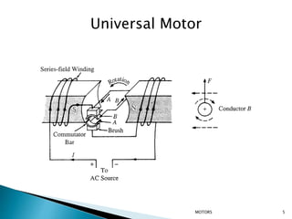
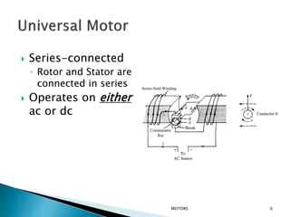
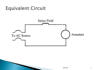
1) A universal motor can operate on either AC or DC power sources. It has series-connected rotor and stator windings.
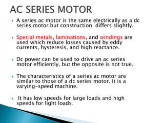
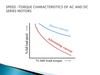
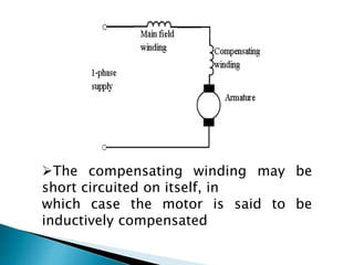
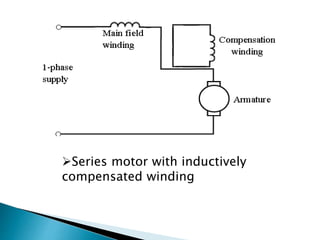
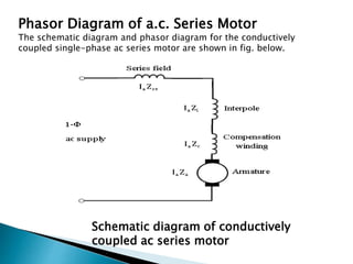
2) An AC series motor is electrically similar to a DC series motor but uses special construction materials to reduce losses from eddy currents.
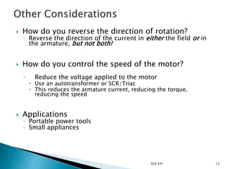
3) Speed control of an AC series motor is similar to a DC series motor and can be achieved through armature resistance/reactance control, field flux control, or armature voltage control. Armature voltage control is commonly used for large motors.