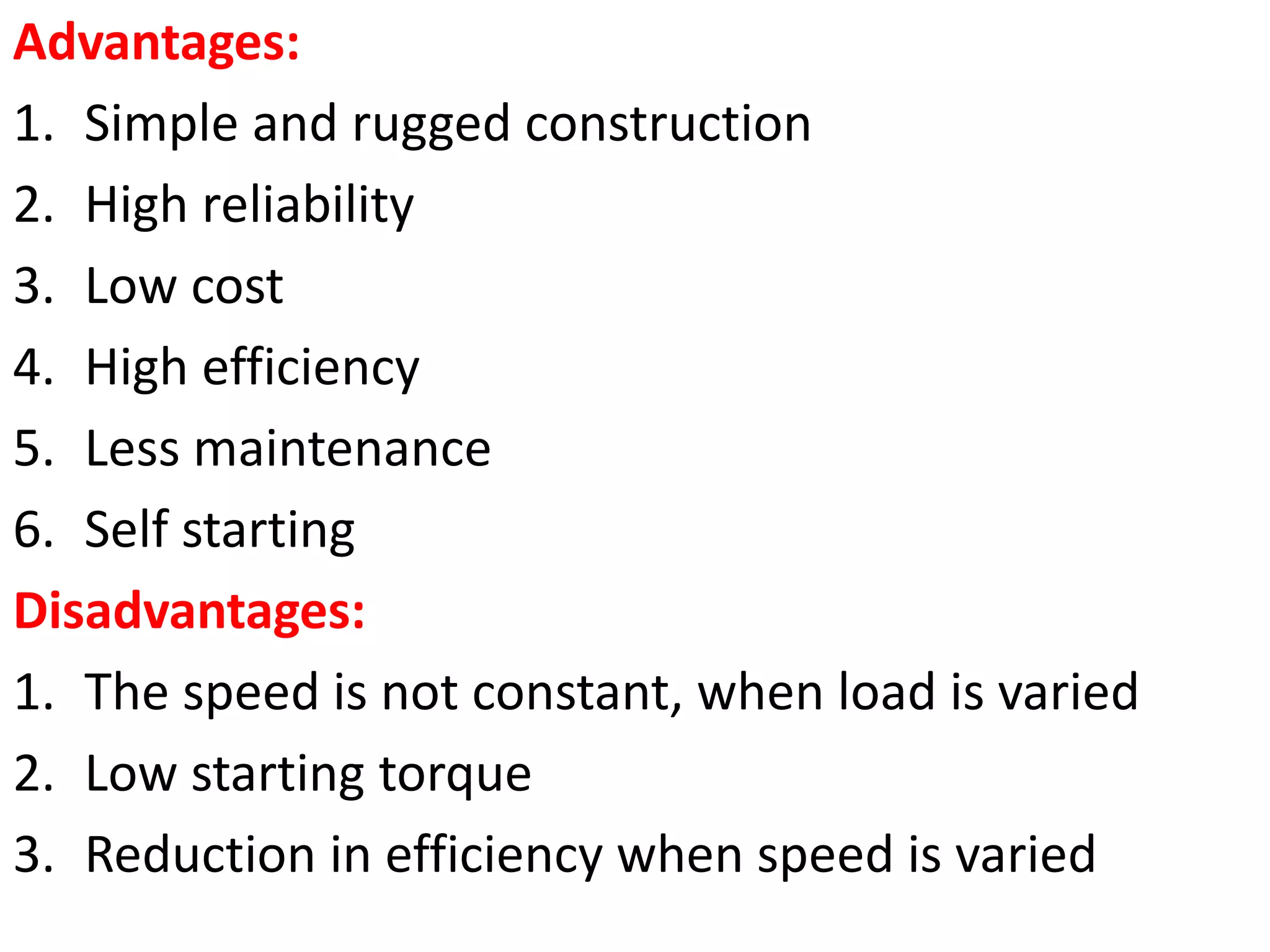
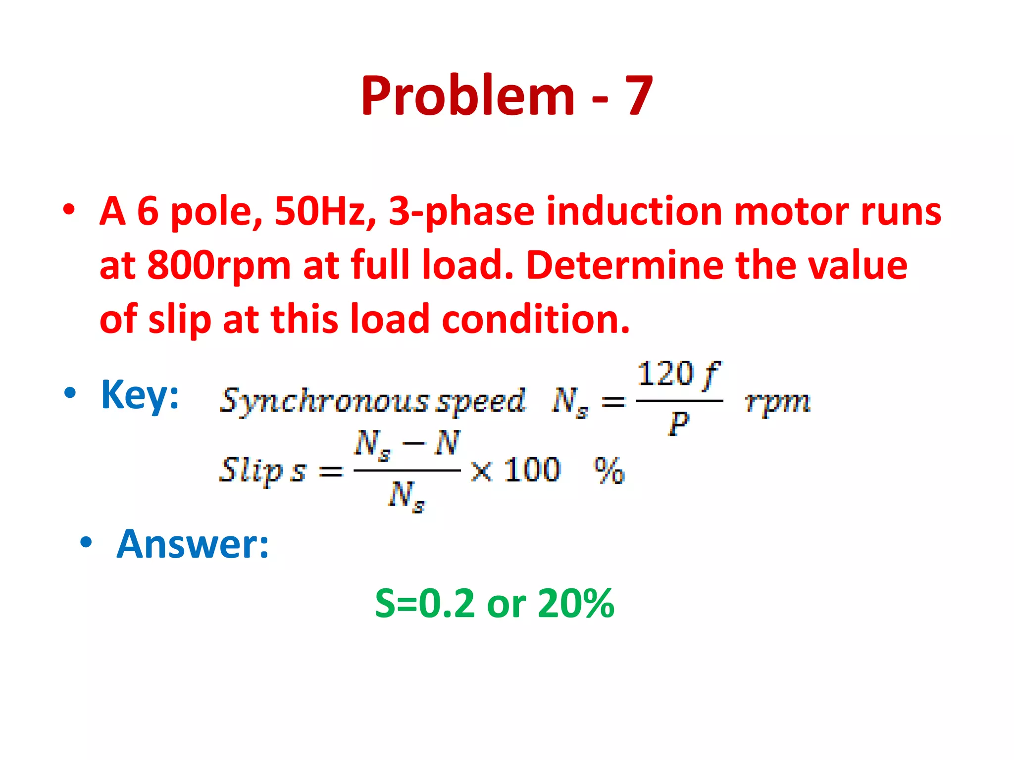
UNIT-III
THREE PHASE INDUCTION MOTORS
Constructional details – Types of rotors –
Squirrel cage and slip ring – Principle of
operation – Slip-Torque equations – Slip-Torque
characteristics – Losses and efficiency – Load
test – No load and blocked rotor test – Cogging
and Crawling – Equivalent circuit – Standard
types of squirrel cage motor – Double cage
rotors – Induction generator – Synchronous
induction motor.
Advantages:
1. Simple and rugged construction
2. High reliability
3. Low cost
4. High efficiency
5. Less maintenance
6. Self starting
Disadvantages:
1. The speed is not constant, when load is varied
2. Low starting torque
3. Reduction in efficiency when speed is varied
Constructional Details
A 3-phase induction motor consists of two main parts
1. Stator
2. Rotor.
1. Stator: It is the stationary part of the motor. It has
three main parts,
(i) Outer frame,
(ii) Stator core
(iii) Stator winding.
2. Rotor: The rotating part of the motor is called rotor.
Two types of rotors
(i) Squirrel cage rotor
(ii) Phase wound rotor.
Stator
(i) Outer frame: It is the outer body of the motor. Its function is to support the stator
core and to protect the inner parts of the machine. For small machines the fame is
casted but for large machines it is fabricated. To place the motor on the foundation,
feet are provided in the outer frame
(ii) Stator core: When AC supply is given to the induction motor, an alternating flux is
set -up in the stator core. This alternating field produces hysteresis and eddy current
loss. To minimise these losses, the core is made of high grade silicon steel
stampings. The stampings are assembled under hydraulic pressure and are keyed to
the frame. Each stamping is insulated from the other with a thin varnish layer. The
thickness to the stamping usually varies from 0.3 to 0.5 mm. Slots are punched on
the inner periphery of the stampings, to accommodate stator winding.
(iii)Stator winding: The stator core carries a three phase winding which is usually
supplied from a three phase supply system. The six terminals of the winding (two of
each phase) are connected in the terminal box of the machine. The stator of the
motor is wound for definite number of poles, the exact number being determined by
the requirement of speed. It will be seen that greater the number of poles, the lower
is the speed and vice-versa, since
𝑁𝑆 =
120𝑓
𝑃
The three- phase winding may be connected in star or delta externally through a starter.
SQUIRREL CAGE ROTOR
(i) The motors in which these rotors are employed are called Squirrel cage
induction motors.
(ii) Because of simple and rugged construction, the most of the induction
motors employed in the industry are of this type.
(iii) A squirrel cage rotor consists of a laminated cylindrical core having
semi-closed circular slots at the outer periphery.
(iv) Copper or aluminium bar conductors are placed in these slots and
short circuited at each end by copper or aluminium rings, called short
circuiting rings in these rotors, the rotor winding is permanently short-
circuited and no external resistance can be added in the rotor circuit.
(v) The slots are not parallel to the shaft but these are skewed.
The skewing provides the following advantages:
(a) Humming is reduced, that ensures quiet running.
(b) At different positions of the rotor, smooth and sufficient torque is
obtained.
(c) It reduces the magnetic locking of the stator and rotor,
(d) It increases the rotor resistance due to the increased length of the rotor
bar conductors.
Phase wound rotor
• Known as slip ring rotor and the motors in which these rotors are employed
are known as phase wound or slip ring induction motors.
• This rotor is also cylindrical in shape which consists of large number of
stampings.
• A number of semi-closed slots are punched at its outer periphery.
• A 3-phase insulated winding is placed in these slots.
• The rotor is wound for the same number of poles as that of stator.
• The rotor winding is connected in star and its remaining three terminals
are connected to the slip rings.
• The rotor core is keyed to the shaft.
• Slip-rings are also keyed to the shaft but these are insulated from the shaft.
• Depending upon the requirement any external resistance can be added in
the rotor circuit.
• In this case also the rotor is skewed.
• A mild steel shaft is passed through the centre of the rotor and is fixed to it
with key. The purpose of shaft is to transfer mechanical power.
Principle of Operation
• When 3-phase supply is given to the stator winding of a 3-phase
wound induction motor
• A revolving field is set up in the stator core.
• The resultant magnetic field set-up by the stator core.
• The direction of the resultant field is marked by an arrow head Fm.
• As per the supply sequence, the field is rotating in an anti-
clockwise direction at synchronous speed 𝝎𝑺radian per second.
• The revolving field is cut by the stationary rotor conductors and
an emf is induced in the rotor conductors.
• The rotor conductors are short circuited, current flows through
them in the direction
• A resultant field Fr is set-up by the rotor current carrying
conductors.
• This field tries to come in line with the stator revolving field Fm,
due to which an electromagnetic torque Te develops and rotor starts
rotating in same direction as that of stator revolving field.
The rotor picks up speed and tries to attain the synchronous speed but
fails to do so. It is because if the rotor attains the synchronous speed
then the relative speed between revolving stator field and rotor will be
zero, no emf will be induced in rotor conductors. No emf means no
current, no rotor field Fr and hence no torque is produced. Thus, an
induction motor can never run at synchronous speed.
It always runs at a speed less than synchronous speed.
Since, the principle of operation of this motor depends upon
electromagnetic induction, hence the name induction motor.
The direction of rotation of a 3-phase induction motor can be reversed
by interchanging the connections of any two supply leads at the stator
Slip
In an induction motor, the speed of rotor is always less than
synchronous speed.
The difference between the speed of revolving field
(Ns) and the rotor speed (N) is called slip.
The slip is usually expressed as a percentage of synchronous
speed (Ns) and is represented by symbol S.
% Slip, %S =
𝑵𝑺−𝑵
𝑵𝑺
× 𝟏𝟎𝟎
Rotor Speed, 𝑵 = 𝑵𝑺(𝟏 − 𝑺)
The difference between synchronous speed and rotor speed is
called slip speed i.e.,
Slip speed = 𝑵𝑺 − 𝑵
The value of slip at full load varies from about 6% small
motors to about 2% for large motors.
Slip-Torque Equations
The torque is proportional to the product of rotor current, flux and rotor power factor
T𝜶 𝝋𝑰𝟐𝒓 𝒄𝒐𝒔 𝝋𝟐𝒓
Where,
• 𝜑 – flux responsible for produce induced emf
• 𝐼2𝑟 – rotor current under running condition
• cos 𝜑2𝑟 – rotor power factor under running condition
Let,
• 𝐸2 – rotor induced emf per phase under standstill condition,
• 𝑋2 – rotor reactance per phase under standstill condition
Rotor frequency at a slip s is 𝒇𝒓 = 𝒔𝒇
• Rotor reactance varies, 𝑿𝟐𝒓 = S𝑿𝟐
𝐸2 𝛼 𝜑 𝐸2𝑟 = 𝑆𝐸2
𝐼2𝑟 =
𝐸2𝑟
𝑍2𝑟
=
𝑠𝐸2
𝑅2
2+(𝑠𝑋2)2
cos 𝜑2𝑟 =
𝑅2
𝑍2𝑟
=
𝑅2
𝑅2
2+(𝑠𝑋2)2
𝜑 𝛼 𝐸2
Torque under running condition is,
T𝛼 𝐸2
𝑅2
𝑅2
2+(𝑠𝑋2)2
𝑠𝐸2
𝑅2
2+(𝑠𝑋2)2
𝛼
𝑠𝐸2
2
𝑅2
𝑅2
2+(𝑠𝑋2)2
T=
𝑘𝑠𝐸2
2
𝑅2
𝑅2
2+(𝑠𝑋2)2 N-m
Where, k- constant of proportionality, K =
3
2𝜋𝑛𝑠
Condition for maximum torque:
Torque T for a fixed input voltage will be maximum when
𝒅𝑻
𝒅𝒔
= 0
∴ 𝑅2
2
+ (𝑠𝑋2)2
𝑘𝐸2
2
𝑅2 - 𝑘𝑠𝐸2
2
𝑅2 2𝑠𝑋2
2
= 0
𝑹𝟐 = s 𝑿𝟐
𝑠𝑚 =
𝑅2
𝑋2
is the slip at which torque is maximum
Then, substituting 𝑠 =
𝑅2
𝑋2
𝑇𝑚𝑎𝑥 =
𝑘𝑠𝐸2
2𝑋2
2𝑆2𝑋2
2
𝑇𝑚𝑎𝑥 =
𝑘𝐸2
2
2𝑋2
The maximum torque is independent of rotor resistance
• Maximum torque is directly proportional to the square of the
induced emf ant standstill (i.e., 𝐸2
2
).
• Maximum torque is inversely proportional to the rotor reactance
𝑋2
Slip – Torque Characteristics
The curve drawn between torque and slip from s=1 (at start) to
s=0(synchronous speed).
T=
𝒌𝒔𝑬𝟐
𝟐
𝑹𝟐
𝑹𝟐
𝟐+(𝒔𝑿𝟐)𝟐 N-m
 Consists of three regions
Stable region
Unstable region
Normal operating region
• Stable region:
a.Slip is very small. The term 𝑠𝑋2
2
is very small compared to𝑅2
2
.
b.Slip is directly proportional to torque.
c.Load increases, speed decreases or slip increases.
d.The characteristics is approximately a straight line
• Unstable region:
a.Slip increased from 𝑠𝑚. The slip value is high
b.The term 𝑅2
2
may be neglected as compared to 𝑠𝑋2
2
c.Torque is inversely proportional to slip. Slip increases and torque
decreases.
d.The characteristics is rectangular hyperbola
Slip – Torque Characteristics
Normal operating region:
a.The region is low slip region and the operating region.
b. The motor is operating in this region continuously.
Losses and Efficiency
Various losses which occur in an induction motor during energy conversions are given below:
(i) Constant losses (ii) Variable losses.
(i) Constant losses:
The losses which are independent of the load and remain constant irrespective of the
load variation are called constant losses.
These losses may be:
(a) Core losses:
These include hysteresis and eddy current losses in stator as well as in rotor core.
Eddy current losses in rotor core is negligible since rotor current frequency is very small of the
order of 0·5 to 2 Hz. These losses are constant or fixed losses since these depend upon voltage
and frequency which is practically constant.
(b) Friction and windage losses:
These losses are also constant as these losses depend upon the speed of the induction
motor. The speed of induction motor is approximately constant (for normal running,
slip is very small). These losses occur in the machine because of power loss due to
friction at the bearings and to overcome wind resistance. Additional sliding friction loss
occur in the slip ring induction motor.
(ii) Variable losses:
The losses which depend on the load and change with the variation
in load are called variable losses. These losses are:
(a) 𝐼2
R loss in stator winding.
(b) 𝐼2
R loss in rotor winding.
• There losses occur due to the resistance of stator winding as well
as resistance of rotor winding. This loss is also called copper loss.
It is proportional to the square of the current
Following in the stator as well as in rotor winding.
(c) Brush contact loss:
This loss occurs only in slip ring induction motors.
This is occurring because of contact resistance between brushes and
slip rings.
Its magnitude is very small since contact resistance is made
minimum
(iii) Stray losses:
These losses are occurring in iron as well winding of the machine.
These cannot be determined exactly but are accounted for when the
efficiency of the machine is calculated, by suitable factor.
Efficiency (𝞰) =
𝑂𝑢𝑡𝑝𝑢𝑡 𝑝𝑜𝑤𝑒𝑟
𝐼𝑛𝑝𝑢𝑡 𝑝𝑜𝑤𝑒𝑟
× 100 =
𝑂𝑢𝑡𝑝𝑢𝑡 𝑝𝑜𝑤𝑒𝑟
𝑜𝑢𝑡𝑝𝑢𝑡 𝑝𝑜𝑤𝑒𝑟+𝑙𝑜𝑠𝑠𝑒𝑠
× 100
Load Test
Tabulation
Line
Voltag
e
(V)
Line
Current
(A)
Wattmeter Reading Spring Balance Speed
N
rpm
I/P
Power
(W1+W2)
Watts
Torque
9.81*r*
(S1˜ S2)
Nm
O/P
Power
(2NT/60)
Watts
Power
Factor
Efficie
ncy
η %
W1 W2
OB AC OB AC S1 S2 S1˜S2
















 
2
1
1
2
1
3
tan
cos
W
W
W
W
PF
MF=
No load and Blocked Rotor Test
No load Test
• With the help of this test, the no load losses, the magnetizing
current and no load power factor is found.
• To apply this test, the rated line voltage at normal frequency
is applied across the stator and the rotor is allowed to run
free without any external mechanical load on it.
• The no load current (I0) and Voltage (Vo) of the motor is
measured with the help of an ammeter & voltmeter
connected in the circuit power input is measured with the
help or two watt meters W1 & W2 connected in the circuit.
• Since the motor runs at no load, the power factor would be
very low. Hence the no load power input to the motor (W0) is
equal to the difference between two wattmeter readings W1
& W2
Calculation
According to the mathematical formula
No load input power, 𝑊0 = 3𝑉𝐿𝐼0 cos ∅0 𝑊𝑎𝑡𝑡𝑠
No load power factor, cos ∅0 =
𝑊0
3𝑉𝐿𝐼0
Where,
VL – Line voltage
𝑉𝑝ℎ =
𝑉𝐿
3
− 𝑝ℎ𝑎𝑠𝑒 𝑣𝑜𝑙𝑡𝑎𝑔𝑒
I0 – No load current
cos ∅0 − 𝑛𝑜 𝑙𝑜𝑎𝑑 𝑝𝑜𝑤𝑒𝑟 𝑓𝑎𝑐𝑡𝑜𝑟
• 𝐼0cos ∅0 = 𝐼𝑊 − 𝐶𝑜𝑟𝑒 𝑙𝑜𝑠𝑠 𝑐𝑜𝑚𝑝𝑜𝑛𝑒𝑛𝑡 𝑜𝑓 𝑐𝑢𝑟𝑟𝑒𝑛𝑡
• 𝐼0𝑠𝑖𝑛 ∅0 = 𝐼𝜇 − 𝑚𝑎𝑔𝑛𝑒𝑡𝑖𝑠𝑖𝑛𝑔 𝑐𝑜𝑚𝑝𝑜𝑛𝑒𝑛𝑡 𝑜𝑓 𝑐𝑢𝑟𝑟𝑒𝑛𝑡
•
𝑉𝑝ℎ
𝐼0cos ∅0
=
𝑉𝑝ℎ
𝐼𝑊
= 𝑅01 − 𝑁𝑜 𝑙𝑜𝑎𝑑 𝑟𝑒𝑠𝑖𝑠𝑡𝑎𝑛𝑐𝑒
•
𝑉𝑝ℎ
𝐼0𝑠𝑖𝑛 ∅0
=
𝑉𝑝ℎ
𝐼𝜇
= 𝑋01 − 𝑁𝑜 𝑙𝑜𝑎𝑑 𝑙𝑒𝑎𝑘𝑎𝑔𝑒 𝑟𝑒𝑎𝑐𝑡𝑎𝑛𝑐𝑒
Blocked Rotor Test
• To apply this test the same connection of no load
test is followed. The difference between the two
tests is that in this test the rotor is locked with the
help of spring balance weight or by hand.
• The rotor windings are short circuited at slip rings if
the motor has wound rotor.
• A reduced voltage is applied to the stator terminals
and is so adjusted that full load current flows in the
stator.
• The value of current, voltage and power input on
short circuit are measured from the ammeter,
voltmeter and wattmeter connected in the circuit
respectively.
Let V be the normal voltage applied to stator and Vsc the short circuit voltage. Then the
relation between the short circuit current Isc and stator applied voltage V is a straight
line, therefore the short circuit current ISN is obtained with normal voltage, and is
calculated as
𝐼𝑆𝑁 = 𝐼𝑠𝑐
𝑉
𝑉𝑠𝑐
𝐴𝑚𝑝𝑠
Where,
Isc – short circuit current with short circuit voltage Vsc
V – normal stator voltage
Vsc – short circuit voltage
• Total power input on short circuit (Wsc) 𝑊
𝑠𝑐 = 3𝑉
𝑠𝑐
′
𝐼𝑠𝑐 cos ∅𝑠𝑐 𝑊𝑎𝑡𝑡𝑠
𝑉
𝑠𝑐
′
− 𝑙𝑖𝑛𝑒 𝑣𝑜𝑙𝑡𝑎𝑔𝑒 𝑜𝑛 𝑠ℎ𝑜𝑟𝑡 𝑐𝑖𝑟𝑐𝑢𝑖𝑡 = 3𝑉
𝑠𝑐
cos ∅𝑠𝑐 =
𝑊𝑠𝑐
3𝑉𝑠𝑐
′𝐼𝑠𝑐
• Equivalent impedance /ph referred to the stator ( Z02)
Z02 – phase voltage at which SC test is made phase current at the test
𝑍02 =
𝑉𝑠𝑐
𝐼𝑠𝑐
Ω
Equivalent resistance/ph referred to stator (R02)
𝑅02 =
𝑊𝑠𝑐−𝑊0
𝐼𝑠𝑐
2
Equivalent reactance per phase referred to stator (X02)
𝑋02 = 𝑍02
2
− 𝑅02
2
Equivalent Circuit
Cogging
In an induction motor, the magnetic circuit is completed through stator
and rotor. It is the tendency of a magnetic circuit to align itself in a
position of minimum reluctance.
Thus, if the number of stator slots is equal to the number of rotor slots,
there exists a position of minimum reluctance
when the teeth of rotor and stator are aligned opposite to each other.
The radial alignment forces become very strong when the machine is at
rest and rotor and stator teeth are aligned.
These forces may exceed the tangential forces of acceleration thereby
preventing the motor from starting.
• Thus, the phenomenon by which the radial alignment forces exceed
the tangential accelerating forces and the machine (induction
motor) refuses to start is called cogging.
• Due to cogging, the rotor of induction motor is locked which may
overheat the motor winding.
• To avoid cogging the number of rotor slots are never made equal to
the number of stator slots.
• Moreover, the rotor is always skewed for smooth running of the rotor.
Crawling
• The fundamental frequency produces the synchronous torque
due to which rotor starts rotating at its rated speed.
• In the induction motors, harmonics are developed out of
which 5th and 7th harmonics are more important.
• These harmonics generate rotor emfs, currents and torques
of the same general torque/speed shape as that of the
fundamental but with synchronous speeds 1/5th (backward)
and 1/7th (forward) of the fundamental synchronous speed.
• The 7th harmonic torque reaches its maximum value just
before 1/7th of synchronous speed,
• Beyond this speed the 7th harmonic torque becomes negative
since the slip in the harmonic field is negative.
• The resultant torque-speed curve combined with 7th
harmonic and fundamental frequency
• Torque due to harmonic flux causes dip in the torque-speed
characteristics.
• When dip in the torque occur due to 7th harmonic and
is insufficient to pick the load, the motor can not
accelerate to its full speed but starts crawling at the
speed corresponding to point ‘a ’.
• Thus, when a 3-phase induction motor continues to
rotor at a speed little lower than the 1/7th
synchronous speed, it is said to be crawling.
• Such operation of a motor is unstable, a momentary
reduction in load may permit the motor to accelerate
to the rated speed.
• The crawling effect can be eliminated by proper choice
of coil pitch and distribution of coils while designing the
winding.
• This reduces the harmonic flux in the air gap to very
low value.
Formula
Problem - 1
• A 6-pole, 3-phase induction motor is
connected to 50Hz supply. If it is running at
960 rpm, find the slip
• Key:
• Answer:
S=0.04 or 4%
Problem - 2
• A 2-pole 3-phase, 50Hz induction motor is
running on no load with a slip of 4%. Calculate i)
The synchronous speed, ii). Speed of the motor.
• Key:
• Answer:
(i). Ns=3000rpm, (ii). 2880rpm
Problem - 3
• A 3-phase, 4-pole, 50Hz induction motor is
running at 1440rpm. Determine the slip
speed and slip.
• Key:
• Answer:
Slip speed =60rpm, Slip = 0.04
Problem - 4
• A 6-pole, 50Hz, 3-phase induction motor
runs at 800rpm at full load. Determine the
value of slip at this load condition.
• Key:
• Answer:
Ns=1000rpm, Slip = 0.2 or 20%
Problem - 5
• A 3-phae, 50Hz induction motor runs at 960rpm
on full load. Find the number of poles and slip
speed. (1000 rpm is the nearest synchronous
speed for 960 rpm)
• Key:
• Answer:
P=6, Slip speed= 40rpm
Problem - 6
• A 3-phase, 6pole, 50Hz induction motor runs
at 950 rpm. Find the slip
• Key:
• Answer:
s=5%
Problem - 7
• A 6 pole, 50Hz, 3-phase induction motor runs
at 800rpm at full load. Determine the value
of slip at this load condition.
• Key:
• Answer:
S=0.2 or 20%
Problem - 8
• A 12 pole, 3-phase alternator driven at a speed of
500rpm, supplies power to an 8 pole, 3-phase
induction motor. If the slip of the motor, at full load is
3%, calculate the full-load speed of the motor.
• Key:
• Answer:
N=727.5 rpm
Problem - 9
• A 4-pole 3-phase induction motor operates from a supply
whose frequency is 50Hz. Calculate (1) the speed of stator
magnetic field (Synchronous speed) and (2) the speed of
rotor (Speed of the motor) when the slip is 0.4.
• Key:
• Answer:
Ns=1500 rpm, N=900rpm
Problem - 10
• A 12pole, 3phase alternator is coupled to an engine
running at 1500rpm. It supplies an induction motor which
has a full-load speed of 1440rpm. Find the slip of the
motor. (induction motor full load speed is 1440 rpm.
Therefore the synchronous speed is 1500rpm)
• Key:
• Answer:
F =50 Hz, s =4%
Problem - 11
• A 8-pole, 3-phase alternator is coupled to prime mover
running at 750rpm. It supplies an induction motor which
has a full load speed of 960rpm. Find the number of poles
of induction motor and slip. (full load speed is 960 rpm.
Therefore the synchronous speed is 1000rpm)
• Key:
• Answer:
f=50 Hz, P=6, s =0.04 or 4%
Frequency of Rotor
• Assume rotor is stationary
– Relative speed between the rotor winding and
rotating magnetic field is Ns
• When the rotor speeds up
– Relative speed is (Ns – N)
• Rotor Frequency
Rotor EMF
• Under Standstill condition slip s=1
– Relative speed is maximum and maximum emf induced in
the rotor
– E2 = rotor induced emf under standstill condition
• When the motor speed increases (running condition)
– Relative speed increases, then induced emf in the rotor
decreases
– E2r = rotor induced emf under running condition
Rotor Current and Power Factor
• R2 = Rotor resistance per ph under standstill condition
• X2 = Rotor reactance per ph under standstill condition
In running condition
Rotor impedance per phase
Problem - 1
• A 3-phase induction motor is suppied at 50Hz and is
wound for 4 poles. Calculate (i) Synchronous speed,
(ii). Apeed when slip is 3%, (iii). Frequency of the
rotor emf when it runs at 1200 rpm
• Key:
• Answer:
Ns=1500rpm; N=1455rpm; fr=10Hz
Problem - 2
• The frequency of emf in the stator of a 4-pole, 3-
phase induction motor is 50Hz and that in the
rotor is 1.5Hz. Determine: i). The Slip, ii). Speed
of the motor.
• Key:
• Answer:
(i). Ns=1500rpm & s=0.03, (ii). N=1455rpm
Problem - 3
• For a 4pole, 3phase, 50Hz induction motor ratio of stator to rotor
turns is 3. On a certain load, its speed is observed to be 1450rpm,
when connected to 415V supply. Calculate:
– i). Frequency of rotor emf in running condition, (fr)
– ii). Magnitude of induced emf in the rotor at standstill, (E2ph)
– iii) Magnitude of induced emf in the rotor under running
condition.(E2r) Assume star connected stator.
• Key:
• Answer:
Fr=1.66Hz; E2ph=79.78V; E2r=2.63V
• Given: P=4, f=50Hz, EIL=415V=stator side line voltage ;
K=rotor turns / stator turns = 1/3 = 0.333; N=1450 rpm
Problem - 4
• A 4-pole three phase, 50Hz, induction motor has a star connected
rotor. The rotor has a resistance of 0.1 ohm per phase and
standstill reactance of 2ohm per phase. The induced emf between
the slip rings is 100V. If full load speed is 1460rpm, find i) Slip, ii).
Rotor frequency, iii). Rotor current, iv). Power factor on full load
condition. Assume slip rings are shorted.
• Key:
• Answer:
S=2.66%; fr=1.33Hz; I2r=13.15A; PF=0.887lagging
• Given: P=4, f=50Hz, R2=0.1ohm; X2=2ohm;
E2=100V, N=1460rpm
Problem - 5
• A 8-pole, 3-phase induction motor is supplied
from 50Hz AC supply. On full load, the
frequency of induced emf in rotor is 2Hz. Find
the full load slip and corresponding speed(N).
• Key:
• Answer:
S=0.04; Ns=750rpm; N=720rpm;
• Given: P=8, f=50Hz, fr=2Hz
Problem - 6
• A 3ph, 6pole, 50Hz induction motor has a slip of 1% at no
load and 3% at full load. Find (1) Synchronous speed(Ns).
(2). No load speed(Nnl). (3). Full load Speed(Nfl). (4).
Frequency of rotor current at standstill(frs). (5) Frequency
of rotor current at full load(frfl).
• Key:
• Answer:
Ns=1000rpm; Nnl=990rpm; Nfl=970rpm; frs=50Hz; frfl=1.5Hz
• Given: P=6, f=50Hz, slip at no load snl=1% or 0.01;
slip at full load sfl=3% or0.03; at standstill slip s=1;
Problem - 7
• If the emf in the stator winding of a 6 pole
induction motor has a frequency of 50c/s and
emf in the rotor has a frequency of 2c/s, find the
speed at which the motor is runing(N) and
percentage slip(s).
• Key:
• Answer:
S=4%; Ns=1000rpm; N=960rpm;
• Given: P=6, supply frequency f=50 c/s,
rotor frequency fr = 2c/s
Problem - 8
• A 3-phase induction motor is wound for 4poles
and is supplied from a 50Hz supply. Calculate the
synchronous speed(Ns), the speed of the
motor(N) when the slip is 3% and the rotor
frequency(fr).
• Key:
• Answer:
Ns=1500rpm; N=1455rpm; fr=1.5Hz;
• Given: P=4, supply frequency f=50Hz,
Slip=3% or 0.03
Problem - 9
• The induced emf between the slip ring terminals of a three phase
induction motor when the rotor is standstill is 100V. The rotor
winding is star connected and has resistance and standstill
reactance of 0.05ohms and 0.1 ohms per phase respectively.
Calculate the voltage and rotor current at (1) 4% slip and (2) 100%
slip(Standstill Condition).
• Key:
• Answer:
(1). For s=0.04, E2r=2.308V, Z2r=0.05ohm;
(2). E2=57.7V; Z2=0.111ohms; I2=519.8A ;
• Given: R2=0.05ohms; X2=0.1ohms;
Problem - 10
• A 3-ph, 50Hz, induction motor runs almost at 960rpm
on full load, when supplied with three-phase supply.
Calculate the following, (i).Number of poles(P), (ii).
Full load slip(s), (iii). Frequency of rotor emf(fr), (iv).
Speed of the motor at 8 percent slip(N).
• Key:
• Answer:
(i).P=6; (ii). S=0.04; (iii).fr=2Hz; (iv).N=920rpm;
• Given: Supply frequency f=50Hz; Speed N
=960rpm; therefore Ns=1000rpm;
Problem - 11
A 1100V, 50Hz delta connected induction motor has a star connected slip ring rotor with a
phase transformation ratio of 3.8. The rotor resistance and stand still leakage reactance
are 0.012ohm and 0.25ohms per phase respectively. Neglecting stator impedance and
magnetising current, determine:
(i). Rotor current at start with slip ring shorted.
(ii). The rotor PF at start with slip ring shorted.
(iii). The rotor current at 4% slip with slip ring shorted.
(iv). The rotor power factor at 4% slip with slip ring shorted.
(v). The external rotor resistance per phase required to obtain a starting current of 100A in
the stator supply lines.
• Key:
• Answer:
(i).I2=1157.2A; (ii). PF=0.048(lagging); (Starting)
(iii).I2r=742A; (iv).PF =0.77(lagging); (running s=4%)
(v). Ext Resistance r=0.707ohms
• Given: Supply voltage V =E1ph(due to delta connection in stator)= 1100V; f=50Hz;
Phase transformation ratio K = 1/3.8=0.263; R2=0.012ohms, X2=0.25ohms;
Problem - 12
• A 3-phase, 4-pole induction motor operates
from a supply whose frequency is 50Hz.
Calculate the frequncy of rotor current at
standstill and the speed at which the magnetic
field of the stator is rotating(Ns).
• Key:
• Answer:
Fr=50Hz; Ns=1500rpm;
• Given: P=4; f=50Hz; at standstill condition s=1;
Problem - 13
• A 4pole three phase squirrel cage induction
motor operates at supply frequency of 50Hz
at a speed at 1440rpm at full load. Find the
frequency of the EMF induced in the rotor(fr).
• Key:
• Answer:
Ns=1500rpm; s=0.04; Fr=2Hz;
• Given: P=4; f=50Hz; N=1440rpm;
Problem - 14
• A3phase 50Hz, 4pole induction motor has a slip of
4%. Calculate (i) Speed of the motor(N) (ii). Frequency
of rotor emf(fr). If the motor has a resistance of 1ohm
and standstill reactance of 4ohm, calculate(iii) power
factor at (a) standstill and (b) a speed of 1400rpm.
• Key:
• Answer:
(i).N=1440rpm; (ii).Fr=2Hz; (iii). (a).PF=0.242 (lagging);
(b).s=0.066; & PF=0.966(lagging)
• Given: P=4; f=50Hz; s=4% or 0.04; R2=1ohm;
X2=4ohm;
Torque Equation
• For DC motor
• For Induction motor
• WKT
• For starting condition (s=1)
Condition for maximum running Torque
• Torque under running condition,
• For maximum torque
• Slip at which the torque is maximum
Torque Relations
Starting torque and maximum torque
Full load torque and maximum torque
Effect of change in supply voltage
•Torque at any speed is proportional to square of
supply voltage
•When supply voltage changes affects Tst, Tmax, Trunning;
•To maintain T=C, slip increases (N decreases)
•When V changes to V1, s to s1
Problem - 1
• A 3-phase 415V, 50Hz, 4pole induction motor has star
connected stator winding. The rotor resistance and
reactance per phase are 0.2ohm and 2ohm
respectively. The full load speed is 1440rpm. Calculate
the torque developed on full load by the motor.
Assume stator to rotor turns ratio as 2:1.
• Key:
• Answer:
Ns=1500rpm; E2ph=119.8V; s=0.04; ns=25rps; T=47.25Nm
• Given: Supply voltage V=415V; P=4;
R2=0.2ohm; X2=2ohm;
Problem - 2
• A 3300V, 10pole, 50Hz, three-phase star connected
inductin motor has a slip ring rotor resistance per
phase=0.015ohm and standstill reactance per phase =
0.25ohm. If the motor runs at 2.5% slip on full load,
find (i). The speed of the motor, (ii). Speed at which
the torque will be maximum, (iii). The ratio of
maximum torque to full load torque.
• Key:
• Answer:
(i).Ns=600rpm; N=585rpm ; (ii). Sm=0.06; N=564rpm;
(iii). Tmax/Tfl=1.408;
• Given: Supply voltage V=3300V; P=10; f=50Hz;
R2=0.015ohm; X2=0.25ohm; slip s=2.5% or 0.025;
Problem - 3
• A 4 pole, 50Hz, 7.46kW motor has at rated
voltage and frequency, at starting torque of 160
percent and a maximum torque of 200 percent
of full-load torque. Determine (1). Full-load
speed(N). (2). Speed at maximum torque(N).
• Key:
• Answer:
Solve (Tst/Tmax) - a=0.04, substitute (Tfl/Tmax)- sf=0.01;
(i).Ns=1500rpm; N=1485rpm ; (ii). Sm=0.04; N=1440rpm;
• Given: P=4; f=50Hz; Tst=1.6Tfl; Tmax=2Tfl;
Power Flow Diagram
Relationship between rotor input (P2),
rotor copper loss (Pcu) and gross
mechanical power (Pm)
• In general Power in terms of torque is
• Power is transferred from stator to rotor
• Gross mechanical power developed by rotor (Pm) is
• Rotor copper loss
Relationship between rotor input (P2),
rotor copper loss (Pcu) and gross
mechanical power (Pm)
Problem - 1
• A 6pole, 3phase induction motor develops a power of
22.38kW, including mechanical losses, which total 1.492kW
at a speed of 950rpm on 550V, 50Hz mains. The power factor
is 0.88. Calculate for this load (i). Slip, (ii). The rotor copper
loss, (iii). The total input iif the stator losses are 2000W, (iv).
The efficiency, (v). The line current, (vi). The number of
complete cycles of the rotor electromotive force per minute.
• Solution
(i). Slip s
• Given: P=6, Pm=22.38kW, PmL=1.492kW, N=950rpm,
V=550V, f=50Hz, PF =0.88;
Problem - 1
• Solution
(ii). Rotor copper loss Pcu
• Given: P=6, Pm=22.38kW, PmL=1.492kW, N=950rpm,
V=550V, f=50Hz, PF =0.88;
(iii). The total input (Pin)
(iv). Efficiency
Problem - 2
• A 37.3kW, 4pole, 50Hz induction motor has friction and
windage losses of 3320 watts. The stator losses equal the
rotor losses. If the motor is deleiverig full load power output
at a speed of 1440rpm, calculate, (i). Synchronous speed, (ii).
Slip (iii). Mechanical power developed by the motor, (iv).
Rotor copper loss, (v). Power transferred from stator to
rotor, (vi) Stator power input, (vii). Efficiency.
• Solution
(i). Synchronous speed(Ns)
• Given: Pout=37.3kW; P=4; f=50Hz; friction and windage losses
Pml=3320W; Stator losses PSL=Rotor Loss Pcu; N=1440rpm.;
(ii). Slip s
Problem - 2
• Solution
(iii). Mechanical power developed by the motor (Pm),
• Given: Pout=37.3kW; P=4; f=50Hz; friction and windage losses
Pml=3320W; Stator losses PSL=Rotor Loss Pcu; N=1440rpm.;
(iv). Rotor copper loss (Pcu),
(v). Power transferred from stator to rotor (P2),
Problem - 2
• Solution
(vi) Stator power input (Pin),
• Given: Pout=37.3kW; P=4; f=50Hz; friction and windage losses
Pml=3320W; Stator losses PSL=Rotor Loss Pcu; N=1440rpm.;
(vii). Efficiency
Problem - 3
• An 18kW, 4pole, 50Hz, 3phase induction motor has
friction and windage loss 500W. The full load slip is
4%. Compute for full load, (i). Rotor copper loss. (ii).
Rotor input. (iii). The shaft torque and (iv). The
gross torque.
• Solution
(i). Rotor copper loss (Pcu),
• Given: Pout=18kW, P=4; f=50Hz; PmL=500W; s=4%;
Problem - 3
• Solution
(ii). Rotor input (P2).
• Given: Pout=18kW, P=4; f=50Hz; PmL=500W; s=4%;
(iii). The shaft torque (Tsh),
(iv). The gross torque(Tg)
A 415V, 3-ph, 50Hz, star connected IM runs 24Rev/Sec on FL.
The rotor resistance and reactance per ph. Are 0.35 and 3.5
ohm. Effective stator to rotor turns ratio 0.85:1. calculate (i)
Slip (ii) TfL (iii)Pout if mech losses are 770W (iv) Tmax (V)
Speed at which Tmax occurs (vi) Starting Torque.
the following data refers to a 10-pole, 400V,
50HZ, 3-ph IM
R1 = 1.75 ohm, X1 = 5.5ohm R2’ = 2.25 ohm
X2’=6.6ohm
I0= 3.8Acore loss 310W S=4% i)I2 ii)I1 coso
iii)Pm
Tg
The following readings were obtained when no-load and blocked rotor
tests were performed on a
3-phase, 400 V, 14.9 kW induction motor:
No-load test: 400 V, 1250 W, 9 A
Blocked rotor test: 150 V, 4000 W, 38 A
Find full-load current and power factor of the motor using circle
diagram.
The following readings were obtained when no-load and blocked rotor
tests were performed on a
3-phase, 400 V, 14.9 kW induction motor:
No-load test: 400 V, 1250 W, 9 A
Blocked rotor test: 150 V, 4000 W, 38 A
Find full-load current and power factor of the motor using circle
diagram.
Solution:
cosΦ𝟎 =
𝑾𝟎
𝟑 × 𝑽𝟎×𝑰𝟎
=
𝟏𝟐𝟓𝟎
𝟑 × 𝟒𝟎𝟎 ×𝟗
= 𝟎. 𝟐𝟎𝟎𝟒
Φ𝟎 = 𝒄𝒐𝒔−𝟏
𝟎. 𝟐𝟎𝟎𝟒 = 𝟕𝟖. 𝟓°
cosΦ𝒃 =
𝑾𝒃
𝟑 × 𝑽𝒃 ×𝑰𝒃
=
𝟒𝟎𝟎𝟎
𝟑 ×𝟏𝟓𝟎 ×𝟑𝟖
= 𝟎. 𝟒𝟎𝟓
Φ𝒃 = 𝒄𝒐𝒔−𝟏
𝟎. 𝟒𝟎𝟓 = 𝟔𝟔. 𝟏°
Short circuit current with normal voltage applied,
𝐼𝑏𝑛 =
𝑉𝐿
𝑉𝑏
× 𝐼𝑏 =
𝟒𝟎𝟎
𝟑
𝟏𝟖𝟎
𝟑
× 38 = 101.3𝐴
Power Drawn at normal voltage,
• 𝑊𝑏𝑛 =
𝑉𝐿
𝑉𝑏
2
× 𝑊𝑏 =
400
3
180
3
2
× 4000 = 28440𝑊
Construction of circle diagram:
• Draw a vector OV along y-axis and X-axis.
• Let the scale for current be 5A = 1cm.
• Draw vector OA i.e., 𝐼0= 9 A (OA=
9
5
= 1.8cm).lagging
behind the voltage vector OV by an Angle Φ𝟎 (i.e.
𝟕𝟖. 𝟓°).
• Draw vector AB i.e., = 101.3A (AB =
101.3
5
= 20.26 cm)
lagging behind the voltage vector OV by an angle
𝟔𝟔. 𝟏°
• Draw horizontal x-axis (OX) perpendicular to OY and
a line AD parallel to x-axis.
• Draw a line AB and and perpendicular bisector
which meet AD at point C.
• Draw a semi circle ABD. With C as center and AC as
radius
• Draw a line BE parallel to Y axis which represents
28440𝑊(Blocked rotor power at rated voltage) and
measure its length(Approx.8.1c.m).
Power Scale is =
28440
8.1
= 3511 W.
Calculation:
Motor rated output=14.9kW(given)
in power scale =
𝟏𝟒𝟗𝟎𝟎
𝟑𝟓𝟏𝟏
= 𝟒. 𝟐𝒄𝒎
For locating full load power on circle extend B to B’ such
that BB’ = 4.2cm. From B’ draw a line parallel to AB which
intersects the semicircle at point L.
From L draw a perpendicular to 𝑥 axis which meets at M.
Line current OL = 6cm = 𝟔 × 𝟓 = 𝟑𝟎𝒄𝒎
OL makes an angle Φ = 30° 𝑤𝑖𝑡ℎ 𝑂𝑉 𝑎𝑥𝑖𝑠.
Power Factor 𝐜𝐨𝐬 30° = 0.886 (Lagging)
O
V
78.5°
A
66.1
B
OA = 1.8cm
OB= 20.26cm
BB’=4.2cm
X
D
C E
B’
L
30°
When no-load and blocked rotor tests were performed on a 3-
phase, 400 V, 50 Hz, star connected induction motor, the
following results were obtained:
No-load test: 400 V, 8.5 A, 1100 W
Blocked-rotor test: 180 V, 45 A, 5700 W
Draw the circle diagram and estimate the line current and power
factor of the motor when operating at 4% slip. The stator
resistance per phase is measured as 0.5 ohm.
Solution: (From No load test)
cosΦ𝟎 =
𝑾𝟎
𝟑 × 𝑽𝟎×𝑰𝟎
=
𝟏𝟏𝟎𝟎
𝟑 × 𝟒𝟎𝟎 ×𝟖.𝟓
= 𝟎. 𝟏𝟖𝟕
Φ𝟎 = 𝒄𝒐𝒔−𝟏 𝟎. 𝟐𝟎𝟎𝟒 = 𝟕𝟗. 𝟐°
(From Blocked rotor test)
cosΦ𝒃 =
𝑾𝒃
𝟑 × 𝑽𝒃 ×𝑰𝒃
=
𝟓𝟕𝟎𝟎
𝟑 ×𝟏𝟖𝟎 ×𝟒𝟓
= 𝟎. 𝟒𝟎𝟔𝟑
Φ𝒃 = 𝒄𝒐𝒔−𝟏 𝟎. 𝟒𝟎𝟔 = 𝟔𝟔°
Short circuit current with normal voltage
applied,
𝐼𝑏𝑛 =
𝑉𝐿
𝑉𝑏
× 𝐼𝑏 =
𝟒𝟎𝟎
𝟑
𝟏𝟖𝟎
𝟑
× 45 = 100 𝐴
Power Drawn at normal voltage,
𝑊𝑏𝑛 =
𝑉𝐿
𝑉𝑏
2
× 𝑊𝑏 =
400
3
150
3
2
× 5700 = 𝟐𝟖𝟏𝟓𝟎𝑾
Construction of circle diagram:
Draw a vector OV along y-axis
Let the scale for current be 10 A = 1cm.
• Draw vector OA i.e., 𝐼0= 8.5 A (OA=
8.5
10
=
0.85cm).lagging behind the voltage vector OV by an
Angle Φ𝟎 (i.e. 𝟕𝟗. 𝟐°).
• Draw vector AB i.e., = 100A (AB =
100
10
= 10 cm)
lagging behind the voltage vector OV by an angle
𝟔𝟔°
• Draw horizontal x-axis (OX) perpendicular to OY and
a line AD parallel to x-axis.
• Draw a line AB and perpendicular bisector which
meet AD at point C.
• Draw a semi circle ABD. With C as center and AC as
radius
• Draw a line BE parallel to Y axis which represents
28440𝑊(Blocked rotor power at rated voltage) and
measure its length(Approx.4.05 c.m).i.e., Total losses at
blocked rotor condition.
Power Scale is =
𝟐𝟖𝟏𝟓𝟎
𝟒.𝟎𝟓
= 6950 W.
Calculation:
• Stator copper loss on short circuit = 3𝐼𝐵𝑁
2
𝑅1 = 3 ×
(100)2
× 0.5 = 15000 𝑊
GF=
𝟏𝟓𝟎𝟎𝟎
𝟔𝟗𝟓𝟎
= 𝟐. 𝟏𝟔 𝒄𝒎
Hence, point G is located on the line BE
Draw the line AG by joining point G with A
From L draw a perpendicular to 𝑥 axis which meets at M.
Now, 𝑠𝑙𝑖𝑝, 𝑆 =
𝑅𝑜𝑡𝑜𝑟 𝑐𝑜𝑝𝑝𝑒𝑟 𝑙𝑜𝑠𝑠
𝑅𝑜𝑡𝑜𝑟 𝑖𝑛𝑝𝑢𝑡
= 0.04 =
𝑁𝐾
𝐿𝐾
Slip (s) =
𝑅𝑜𝑡𝑜𝑟 𝑐𝑜𝑝𝑝𝑒𝑟 𝑙𝑜𝑠𝑠
𝑅𝑜𝑡𝑜𝑟 𝑖𝑛𝑝𝑢𝑡
= 0.05 =
𝑁𝐾
𝐿𝐾
• Using this ratio locate point L on the circle
Thus, line current, 𝐼𝐿= OL = 2.42 cm = 10 × 2.42 = 24.2
A (Ans.)
• Power factor, cos Φ= 0.866 lagging
O
V
79.2°
A
66
B
OA = 1.7cm
Φ𝟎 = 𝟕𝟗. 𝟐°
OB= 20.26cm
Φ𝒃 = 𝟔𝟔°
X
D
C E
30°
o
A
B
C
D
B’
E
L
78.5
66.1 F
G
OA = 1.8cm
Φ𝟎 = 𝟕𝟗. 𝟐°
OB= 20.26cm
Φ𝒃 = 𝟔𝟔°
BB’=4.2cm
Draw the circle diagram for a 5.6kW, 400V, 3-ph,4-pole,50Hz slip ring
induction motor.
No-load test: 400 V, 6 A, 𝐜𝐨𝐬 𝝋𝟎 = 𝟎. 𝟎𝟖𝟕
Blocked-rotor test: 100 V, 12 A, 720 W
The ratio of primary to secondary turns is 2.62. stator resistance per
phase is 0.67Ω and rotor is 0.185Ω. Calculate (i) Full load current (ii)
Maximum output (iii)Full load slip (iv) Full load power factor (v) Ratio
between maximum torque to full load torque.
Solution:
From no load condition,
power factor cosΦ𝟎 = 0.087
Φ𝟎 = 𝒄𝒐𝒔−𝟏 𝟎. 𝟎𝟖𝟕 = 𝟖𝟓°
From blocked rotor condition,
cosΦ𝒃 =
𝑾𝒃
𝟑 × 𝑽𝒃 ×𝑰𝒃
=
𝟕𝟐𝟎
𝟑 ×𝟏𝟎𝟎 × 𝟏𝟐
= 𝟎. 𝟑𝟎𝟕
Φ𝒃 = 𝒄𝒐𝒔−𝟏 𝟎. 𝟑𝟎𝟕 = 𝟔𝟗. 𝟕𝟑°
Short circuit current with normal voltage applied,
𝐼𝑏𝑛 =
𝑉𝐿
𝑉𝑏
× 𝐼𝑏 =
𝟒𝟎𝟎
𝟑
𝟏𝟎𝟎
𝟑
× 12 = 48𝐴
Short circuit Power Drawn at normal voltage,
• 𝑊𝑏𝑛 =
𝑉𝐿
𝑉𝑏
2
× 𝑊𝑏 =
400
3
100
3
2
× 720 = 11520𝑊
Construction of circle diagram:
• Draw a vector OV along y-axis and X-axis.
• Let the scale for current be 5A = 1cm.
• Draw vector OA i.e., 𝐼0= 6 A (OA=
6
5
= 1.2cm).lagging
behind the voltage vector OV by an Angle Φ𝟎 (i.e.
𝟖𝟓°).
• Draw vector AB i.e., = 48A (AB =
48
5
= 9.6 cm) lagging
behind the voltage vector OV by an angle 𝟔𝟗. 𝟕𝟑°
• Draw horizontal x-axis (OX) perpendicular to OY and
a line AD parallel to x-axis.
• Draw a line AB and and perpendicular bisector
which meet AD at point C.
• Draw a semi circle ABD. With C as center and AC as
radius
Draw a line BE parallel to Y axis which represents
11520𝑊(Blocked rotor power at rated voltage) and
measure its length(Approx. 3.5 c.m).i.e., Total losses
at blocked rotor condition.
Power Scale is =
𝟏𝟏𝟓𝟐𝟎
𝟑.𝟓
= 3200 W.
(Power scale 1cm = 3200W)
Procedure to draw torque line:
∴
𝑅𝑜𝑡𝑜𝑟 𝑐𝑜𝑝𝑝𝑒𝑟 𝑙𝑜𝑠𝑠(𝐵𝐺)
𝑠𝑡𝑎𝑡𝑜𝑟 𝑐𝑜𝑝𝑝𝑒𝑟 𝑙𝑜𝑠𝑠(𝐺𝐹)
= 2.622
×
0.185
0.67
= 1.9
AG is the torque line
Full load output power = 5.6kW
In power scale :
5.6
3.2
= 1.75cm
i) Full load current OL = 3cm = 15A
ii) Maximum output(PmR) = 3cm = 3 × 3200 = 9.6W
iii) Full load slip S = 0.09
𝑅𝑜𝑡𝑜𝑟 𝐶𝑢 𝑙𝑜𝑠𝑠(𝑀𝑁)
𝑅𝑜𝑡𝑜𝑟 𝑖𝑛𝑝𝑢𝑡(𝐿𝑁)
= 𝑆
iv) Power Factor = 0.83(lag)
v)
𝑇max(𝑇𝑚𝑆)
𝑇𝑓𝑙(𝐿𝑁)
=
3.8
2.2
= 1.72
vi) Efficiency =
𝑂𝑢𝑡𝑝𝑢𝑡 𝑝𝑜𝑤𝑒𝑟(𝐿𝑁)
𝐼𝑛𝑝𝑢𝑡 𝑃𝑜𝑤𝑒𝑟(𝐿𝑄)
O
V
85°
A
69.73
B
OA = 1.2cm
Φ𝟎 = 85°
OB= 9.6cm
Φ𝒃 = 𝟔𝟗. 𝟕𝟑°
X
D
C E
33°
F
G
K
L
M
N
P
Q
𝑃𝑚
R
𝑇𝑚
S
Double Cage Induction Motor: Construction, Working
Why Double Cage IM?
One of the advantages of the slip-ring motor is that
resistance may be inserted in the rotor circuit to
obtain high starting torque (at low starting current)
and then cut out to obtain optimum running
conditions.
However, such a procedure cannot be adopted for a
squirrel cage motor because its cage is permanently
short-circuited. In order to provide high starting
torque at low starting current, double-cage
construction is used.
The outer winding consists of bars of smaller cross-
section short-circuited by end rings. Therefore, the
resistance of this winding is high. Since the outer winding
has relatively open slots and a poorer flux path around its
bars it has a low inductance. Thus the resistance of the
outer squirrel-cage winding is high and its inductance is
low.
The inner winding consists of bars of greater cross-
section short-circuited by end rings. Therefore, the
resistance of this winding is low. Since the bars of the
inner winding are thoroughly buried in iron, it has a high
inductance Thus the resistance of the inner squirrel cage
winding is low and its inductance is high.
OUTER CAGE - high resistance, low reactance.
INNER CAGE - low resistance, high reactance.
i) At starting, the rotor frequency is the same as that
of the line (i.e., 50 Hz), making the reactance of the
lower winding much higher than that of the upper
winding. Because of the high reactance of the lower
winding, nearly all the rotor current flows in the high-
resistance outer cage winding. This provides the good
starting characteristics of a high-resistance cage
winding. Thus the outer winding gives high starting
torque at low starting current.
(ii) As the motor accelerates, the rotor frequency
decreases, thereby lowering the reactance of the
inner winding, allowing it to carry a larger proportion
of the total rotor current At the normal operating
speed of the motor, the rotor frequency is so low (2 to
3 Hz) that nearly all the rotor current flows in the low-
resistance inner cage winding. This results in good
operating efficiency and speed regulation.
keep in mind that during starting, current flows
through outer cage.
Under normal running conditions , current flows
through inner cage.
•
Important Points for Double cage Induction Motor
1. Higher starting torque
2. Outer cage increases CU loss due to high resistance
3. Inner cage reduces full load power factor
4. Efficiency reduces
5. Cost is higher
Cogging:
• In an induction motor, the magnetic circuit is completed through
stator and rotor. It is the tendency of a magnetic circuit to align
itself in a position of minimum reluctance. Thus, if the number
of stator slots is equal to the number of rotor slots, there exists a
position of minimum reluctance when the teeth of rotor and
stator are aligned opposite to each other. The radial alignment
forces become very strong when the machine is at rest and rotor
and stator teeth are aligned. These forces may exceed the
tangential forces of acceleration thereby preventing the motor
from starting.
• Thus, the phenomenon by which the radial alignment forces
exceed the tangential accelerating forces and the machine
(induction motor) refuses to start is called cogging.
• Due to cogging, the rotor of induction motor is locked which
may overheat the motor winding.
• To avoid cogging the number of rotor slots are never made
equal to the number of stator slots.
• Moreover, the rotor is always skewed for smooth running of the
rotor.
Crawling in Three-phase Induction Motors:
• In a three-phase induction motor, the fundamental frequency produces the synchronous torque
due
• to which rotor starts rotating at its rated speed. However, in the induction motors, harmonics are
• developed out of which 5th and 7th harmonics are more important. These harmonics generate
rotor
• emfs, currents and torques of the same general torque/speed shape as that of the fundamental
but with
• synchronous speeds 1/5th (backward) and 1/7th (forward) of the fundamental synchronous
speed.
• The 7th harmonic torque reaches its maximum value just before 1/7th of synchronous speed, but
• beyond this speed the 7th harmonic torque becomes negative since the slip in the harmonic field
is
• negative. The resultant torque-speed curve combined with 7th harmonic and fundamental
frequency
• is shown in Fig. 9.48. Torque due to harmonic flux causes dip in the torque-speed characteristics.
• When dip in the torque occur due to 7th harmonic and is insufficient to pick the load, the motor
• can not accelerate to its full speed but starts crawling at the speed corresponding to point ‘a ’.
• Thus, when a 3-phase induction motor continues to rotor at a speed little lower than the 1/7th
• synchronous speed, it is said to be crawling.
• Such operation of a motor is unstable, a momentary reduction in load may permit the motor to
• accelerate to the rated speed. In fact, the crawling effect can be eliminated by proper choice of
coil
• pitch and distribution of coils while designing the winding. This reduces the harmonic flux in the
• air gap to very low value.

Induction Motors.pptx

  • 1.
    UNIT-III THREE PHASE INDUCTIONMOTORS Constructional details – Types of rotors – Squirrel cage and slip ring – Principle of operation – Slip-Torque equations – Slip-Torque characteristics – Losses and efficiency – Load test – No load and blocked rotor test – Cogging and Crawling – Equivalent circuit – Standard types of squirrel cage motor – Double cage rotors – Induction generator – Synchronous induction motor.
  • 2.
    Advantages: 1. Simple andrugged construction 2. High reliability 3. Low cost 4. High efficiency 5. Less maintenance 6. Self starting Disadvantages: 1. The speed is not constant, when load is varied 2. Low starting torque 3. Reduction in efficiency when speed is varied
  • 3.
    Constructional Details A 3-phaseinduction motor consists of two main parts 1. Stator 2. Rotor. 1. Stator: It is the stationary part of the motor. It has three main parts, (i) Outer frame, (ii) Stator core (iii) Stator winding. 2. Rotor: The rotating part of the motor is called rotor. Two types of rotors (i) Squirrel cage rotor (ii) Phase wound rotor.
  • 4.
  • 5.
    (i) Outer frame:It is the outer body of the motor. Its function is to support the stator core and to protect the inner parts of the machine. For small machines the fame is casted but for large machines it is fabricated. To place the motor on the foundation, feet are provided in the outer frame (ii) Stator core: When AC supply is given to the induction motor, an alternating flux is set -up in the stator core. This alternating field produces hysteresis and eddy current loss. To minimise these losses, the core is made of high grade silicon steel stampings. The stampings are assembled under hydraulic pressure and are keyed to the frame. Each stamping is insulated from the other with a thin varnish layer. The thickness to the stamping usually varies from 0.3 to 0.5 mm. Slots are punched on the inner periphery of the stampings, to accommodate stator winding. (iii)Stator winding: The stator core carries a three phase winding which is usually supplied from a three phase supply system. The six terminals of the winding (two of each phase) are connected in the terminal box of the machine. The stator of the motor is wound for definite number of poles, the exact number being determined by the requirement of speed. It will be seen that greater the number of poles, the lower is the speed and vice-versa, since 𝑁𝑆 = 120𝑓 𝑃 The three- phase winding may be connected in star or delta externally through a starter.
  • 6.
    SQUIRREL CAGE ROTOR (i)The motors in which these rotors are employed are called Squirrel cage induction motors. (ii) Because of simple and rugged construction, the most of the induction motors employed in the industry are of this type. (iii) A squirrel cage rotor consists of a laminated cylindrical core having semi-closed circular slots at the outer periphery. (iv) Copper or aluminium bar conductors are placed in these slots and short circuited at each end by copper or aluminium rings, called short circuiting rings in these rotors, the rotor winding is permanently short- circuited and no external resistance can be added in the rotor circuit. (v) The slots are not parallel to the shaft but these are skewed. The skewing provides the following advantages: (a) Humming is reduced, that ensures quiet running. (b) At different positions of the rotor, smooth and sufficient torque is obtained. (c) It reduces the magnetic locking of the stator and rotor, (d) It increases the rotor resistance due to the increased length of the rotor bar conductors.
  • 8.
    Phase wound rotor •Known as slip ring rotor and the motors in which these rotors are employed are known as phase wound or slip ring induction motors. • This rotor is also cylindrical in shape which consists of large number of stampings. • A number of semi-closed slots are punched at its outer periphery. • A 3-phase insulated winding is placed in these slots. • The rotor is wound for the same number of poles as that of stator. • The rotor winding is connected in star and its remaining three terminals are connected to the slip rings. • The rotor core is keyed to the shaft. • Slip-rings are also keyed to the shaft but these are insulated from the shaft. • Depending upon the requirement any external resistance can be added in the rotor circuit. • In this case also the rotor is skewed. • A mild steel shaft is passed through the centre of the rotor and is fixed to it with key. The purpose of shaft is to transfer mechanical power.
  • 10.
    Principle of Operation •When 3-phase supply is given to the stator winding of a 3-phase wound induction motor • A revolving field is set up in the stator core. • The resultant magnetic field set-up by the stator core. • The direction of the resultant field is marked by an arrow head Fm. • As per the supply sequence, the field is rotating in an anti- clockwise direction at synchronous speed 𝝎𝑺radian per second. • The revolving field is cut by the stationary rotor conductors and an emf is induced in the rotor conductors. • The rotor conductors are short circuited, current flows through them in the direction • A resultant field Fr is set-up by the rotor current carrying conductors. • This field tries to come in line with the stator revolving field Fm, due to which an electromagnetic torque Te develops and rotor starts rotating in same direction as that of stator revolving field.
  • 11.
    The rotor picksup speed and tries to attain the synchronous speed but fails to do so. It is because if the rotor attains the synchronous speed then the relative speed between revolving stator field and rotor will be zero, no emf will be induced in rotor conductors. No emf means no current, no rotor field Fr and hence no torque is produced. Thus, an induction motor can never run at synchronous speed. It always runs at a speed less than synchronous speed. Since, the principle of operation of this motor depends upon electromagnetic induction, hence the name induction motor. The direction of rotation of a 3-phase induction motor can be reversed by interchanging the connections of any two supply leads at the stator
  • 12.
    Slip In an inductionmotor, the speed of rotor is always less than synchronous speed. The difference between the speed of revolving field (Ns) and the rotor speed (N) is called slip. The slip is usually expressed as a percentage of synchronous speed (Ns) and is represented by symbol S. % Slip, %S = 𝑵𝑺−𝑵 𝑵𝑺 × 𝟏𝟎𝟎 Rotor Speed, 𝑵 = 𝑵𝑺(𝟏 − 𝑺) The difference between synchronous speed and rotor speed is called slip speed i.e., Slip speed = 𝑵𝑺 − 𝑵 The value of slip at full load varies from about 6% small motors to about 2% for large motors.
  • 13.
    Slip-Torque Equations The torqueis proportional to the product of rotor current, flux and rotor power factor T𝜶 𝝋𝑰𝟐𝒓 𝒄𝒐𝒔 𝝋𝟐𝒓 Where, • 𝜑 – flux responsible for produce induced emf • 𝐼2𝑟 – rotor current under running condition • cos 𝜑2𝑟 – rotor power factor under running condition Let, • 𝐸2 – rotor induced emf per phase under standstill condition, • 𝑋2 – rotor reactance per phase under standstill condition Rotor frequency at a slip s is 𝒇𝒓 = 𝒔𝒇 • Rotor reactance varies, 𝑿𝟐𝒓 = S𝑿𝟐 𝐸2 𝛼 𝜑 𝐸2𝑟 = 𝑆𝐸2 𝐼2𝑟 = 𝐸2𝑟 𝑍2𝑟 = 𝑠𝐸2 𝑅2 2+(𝑠𝑋2)2 cos 𝜑2𝑟 = 𝑅2 𝑍2𝑟 = 𝑅2 𝑅2 2+(𝑠𝑋2)2 𝜑 𝛼 𝐸2 Torque under running condition is, T𝛼 𝐸2 𝑅2 𝑅2 2+(𝑠𝑋2)2 𝑠𝐸2 𝑅2 2+(𝑠𝑋2)2 𝛼 𝑠𝐸2 2 𝑅2 𝑅2 2+(𝑠𝑋2)2 T= 𝑘𝑠𝐸2 2 𝑅2 𝑅2 2+(𝑠𝑋2)2 N-m Where, k- constant of proportionality, K = 3 2𝜋𝑛𝑠
  • 14.
    Condition for maximumtorque: Torque T for a fixed input voltage will be maximum when 𝒅𝑻 𝒅𝒔 = 0 ∴ 𝑅2 2 + (𝑠𝑋2)2 𝑘𝐸2 2 𝑅2 - 𝑘𝑠𝐸2 2 𝑅2 2𝑠𝑋2 2 = 0 𝑹𝟐 = s 𝑿𝟐 𝑠𝑚 = 𝑅2 𝑋2 is the slip at which torque is maximum Then, substituting 𝑠 = 𝑅2 𝑋2 𝑇𝑚𝑎𝑥 = 𝑘𝑠𝐸2 2𝑋2 2𝑆2𝑋2 2 𝑇𝑚𝑎𝑥 = 𝑘𝐸2 2 2𝑋2 The maximum torque is independent of rotor resistance • Maximum torque is directly proportional to the square of the induced emf ant standstill (i.e., 𝐸2 2 ). • Maximum torque is inversely proportional to the rotor reactance 𝑋2
  • 15.
    Slip – TorqueCharacteristics The curve drawn between torque and slip from s=1 (at start) to s=0(synchronous speed). T= 𝒌𝒔𝑬𝟐 𝟐 𝑹𝟐 𝑹𝟐 𝟐+(𝒔𝑿𝟐)𝟐 N-m  Consists of three regions Stable region Unstable region Normal operating region • Stable region: a.Slip is very small. The term 𝑠𝑋2 2 is very small compared to𝑅2 2 . b.Slip is directly proportional to torque. c.Load increases, speed decreases or slip increases. d.The characteristics is approximately a straight line • Unstable region: a.Slip increased from 𝑠𝑚. The slip value is high b.The term 𝑅2 2 may be neglected as compared to 𝑠𝑋2 2 c.Torque is inversely proportional to slip. Slip increases and torque decreases. d.The characteristics is rectangular hyperbola
  • 16.
    Slip – TorqueCharacteristics Normal operating region: a.The region is low slip region and the operating region. b. The motor is operating in this region continuously.
  • 17.
    Losses and Efficiency Variouslosses which occur in an induction motor during energy conversions are given below: (i) Constant losses (ii) Variable losses. (i) Constant losses: The losses which are independent of the load and remain constant irrespective of the load variation are called constant losses. These losses may be: (a) Core losses: These include hysteresis and eddy current losses in stator as well as in rotor core. Eddy current losses in rotor core is negligible since rotor current frequency is very small of the order of 0·5 to 2 Hz. These losses are constant or fixed losses since these depend upon voltage and frequency which is practically constant. (b) Friction and windage losses: These losses are also constant as these losses depend upon the speed of the induction motor. The speed of induction motor is approximately constant (for normal running, slip is very small). These losses occur in the machine because of power loss due to friction at the bearings and to overcome wind resistance. Additional sliding friction loss occur in the slip ring induction motor.
  • 18.
    (ii) Variable losses: Thelosses which depend on the load and change with the variation in load are called variable losses. These losses are: (a) 𝐼2 R loss in stator winding. (b) 𝐼2 R loss in rotor winding. • There losses occur due to the resistance of stator winding as well as resistance of rotor winding. This loss is also called copper loss. It is proportional to the square of the current Following in the stator as well as in rotor winding. (c) Brush contact loss: This loss occurs only in slip ring induction motors. This is occurring because of contact resistance between brushes and slip rings. Its magnitude is very small since contact resistance is made minimum (iii) Stray losses: These losses are occurring in iron as well winding of the machine. These cannot be determined exactly but are accounted for when the efficiency of the machine is calculated, by suitable factor.
  • 19.
    Efficiency (𝞰) = 𝑂𝑢𝑡𝑝𝑢𝑡𝑝𝑜𝑤𝑒𝑟 𝐼𝑛𝑝𝑢𝑡 𝑝𝑜𝑤𝑒𝑟 × 100 = 𝑂𝑢𝑡𝑝𝑢𝑡 𝑝𝑜𝑤𝑒𝑟 𝑜𝑢𝑡𝑝𝑢𝑡 𝑝𝑜𝑤𝑒𝑟+𝑙𝑜𝑠𝑠𝑒𝑠 × 100
  • 20.
  • 21.
    Tabulation Line Voltag e (V) Line Current (A) Wattmeter Reading SpringBalance Speed N rpm I/P Power (W1+W2) Watts Torque 9.81*r* (S1˜ S2) Nm O/P Power (2NT/60) Watts Power Factor Efficie ncy η % W1 W2 OB AC OB AC S1 S2 S1˜S2                   2 1 1 2 1 3 tan cos W W W W PF MF=
  • 22.
    No load andBlocked Rotor Test
  • 23.
    No load Test •With the help of this test, the no load losses, the magnetizing current and no load power factor is found. • To apply this test, the rated line voltage at normal frequency is applied across the stator and the rotor is allowed to run free without any external mechanical load on it. • The no load current (I0) and Voltage (Vo) of the motor is measured with the help of an ammeter & voltmeter connected in the circuit power input is measured with the help or two watt meters W1 & W2 connected in the circuit. • Since the motor runs at no load, the power factor would be very low. Hence the no load power input to the motor (W0) is equal to the difference between two wattmeter readings W1 & W2
  • 24.
    Calculation According to themathematical formula No load input power, 𝑊0 = 3𝑉𝐿𝐼0 cos ∅0 𝑊𝑎𝑡𝑡𝑠 No load power factor, cos ∅0 = 𝑊0 3𝑉𝐿𝐼0 Where, VL – Line voltage 𝑉𝑝ℎ = 𝑉𝐿 3 − 𝑝ℎ𝑎𝑠𝑒 𝑣𝑜𝑙𝑡𝑎𝑔𝑒 I0 – No load current cos ∅0 − 𝑛𝑜 𝑙𝑜𝑎𝑑 𝑝𝑜𝑤𝑒𝑟 𝑓𝑎𝑐𝑡𝑜𝑟 • 𝐼0cos ∅0 = 𝐼𝑊 − 𝐶𝑜𝑟𝑒 𝑙𝑜𝑠𝑠 𝑐𝑜𝑚𝑝𝑜𝑛𝑒𝑛𝑡 𝑜𝑓 𝑐𝑢𝑟𝑟𝑒𝑛𝑡 • 𝐼0𝑠𝑖𝑛 ∅0 = 𝐼𝜇 − 𝑚𝑎𝑔𝑛𝑒𝑡𝑖𝑠𝑖𝑛𝑔 𝑐𝑜𝑚𝑝𝑜𝑛𝑒𝑛𝑡 𝑜𝑓 𝑐𝑢𝑟𝑟𝑒𝑛𝑡 • 𝑉𝑝ℎ 𝐼0cos ∅0 = 𝑉𝑝ℎ 𝐼𝑊 = 𝑅01 − 𝑁𝑜 𝑙𝑜𝑎𝑑 𝑟𝑒𝑠𝑖𝑠𝑡𝑎𝑛𝑐𝑒 • 𝑉𝑝ℎ 𝐼0𝑠𝑖𝑛 ∅0 = 𝑉𝑝ℎ 𝐼𝜇 = 𝑋01 − 𝑁𝑜 𝑙𝑜𝑎𝑑 𝑙𝑒𝑎𝑘𝑎𝑔𝑒 𝑟𝑒𝑎𝑐𝑡𝑎𝑛𝑐𝑒
  • 25.
    Blocked Rotor Test •To apply this test the same connection of no load test is followed. The difference between the two tests is that in this test the rotor is locked with the help of spring balance weight or by hand. • The rotor windings are short circuited at slip rings if the motor has wound rotor. • A reduced voltage is applied to the stator terminals and is so adjusted that full load current flows in the stator. • The value of current, voltage and power input on short circuit are measured from the ammeter, voltmeter and wattmeter connected in the circuit respectively.
  • 26.
    Let V bethe normal voltage applied to stator and Vsc the short circuit voltage. Then the relation between the short circuit current Isc and stator applied voltage V is a straight line, therefore the short circuit current ISN is obtained with normal voltage, and is calculated as 𝐼𝑆𝑁 = 𝐼𝑠𝑐 𝑉 𝑉𝑠𝑐 𝐴𝑚𝑝𝑠 Where, Isc – short circuit current with short circuit voltage Vsc V – normal stator voltage Vsc – short circuit voltage • Total power input on short circuit (Wsc) 𝑊 𝑠𝑐 = 3𝑉 𝑠𝑐 ′ 𝐼𝑠𝑐 cos ∅𝑠𝑐 𝑊𝑎𝑡𝑡𝑠 𝑉 𝑠𝑐 ′ − 𝑙𝑖𝑛𝑒 𝑣𝑜𝑙𝑡𝑎𝑔𝑒 𝑜𝑛 𝑠ℎ𝑜𝑟𝑡 𝑐𝑖𝑟𝑐𝑢𝑖𝑡 = 3𝑉 𝑠𝑐 cos ∅𝑠𝑐 = 𝑊𝑠𝑐 3𝑉𝑠𝑐 ′𝐼𝑠𝑐 • Equivalent impedance /ph referred to the stator ( Z02) Z02 – phase voltage at which SC test is made phase current at the test 𝑍02 = 𝑉𝑠𝑐 𝐼𝑠𝑐 Ω Equivalent resistance/ph referred to stator (R02) 𝑅02 = 𝑊𝑠𝑐−𝑊0 𝐼𝑠𝑐 2 Equivalent reactance per phase referred to stator (X02) 𝑋02 = 𝑍02 2 − 𝑅02 2
  • 27.
  • 28.
    Cogging In an inductionmotor, the magnetic circuit is completed through stator and rotor. It is the tendency of a magnetic circuit to align itself in a position of minimum reluctance. Thus, if the number of stator slots is equal to the number of rotor slots, there exists a position of minimum reluctance when the teeth of rotor and stator are aligned opposite to each other. The radial alignment forces become very strong when the machine is at rest and rotor and stator teeth are aligned. These forces may exceed the tangential forces of acceleration thereby preventing the motor from starting. • Thus, the phenomenon by which the radial alignment forces exceed the tangential accelerating forces and the machine (induction motor) refuses to start is called cogging. • Due to cogging, the rotor of induction motor is locked which may overheat the motor winding. • To avoid cogging the number of rotor slots are never made equal to the number of stator slots. • Moreover, the rotor is always skewed for smooth running of the rotor.
  • 29.
    Crawling • The fundamentalfrequency produces the synchronous torque due to which rotor starts rotating at its rated speed. • In the induction motors, harmonics are developed out of which 5th and 7th harmonics are more important. • These harmonics generate rotor emfs, currents and torques of the same general torque/speed shape as that of the fundamental but with synchronous speeds 1/5th (backward) and 1/7th (forward) of the fundamental synchronous speed. • The 7th harmonic torque reaches its maximum value just before 1/7th of synchronous speed, • Beyond this speed the 7th harmonic torque becomes negative since the slip in the harmonic field is negative. • The resultant torque-speed curve combined with 7th harmonic and fundamental frequency • Torque due to harmonic flux causes dip in the torque-speed characteristics.
  • 31.
    • When dipin the torque occur due to 7th harmonic and is insufficient to pick the load, the motor can not accelerate to its full speed but starts crawling at the speed corresponding to point ‘a ’. • Thus, when a 3-phase induction motor continues to rotor at a speed little lower than the 1/7th synchronous speed, it is said to be crawling. • Such operation of a motor is unstable, a momentary reduction in load may permit the motor to accelerate to the rated speed. • The crawling effect can be eliminated by proper choice of coil pitch and distribution of coils while designing the winding. • This reduces the harmonic flux in the air gap to very low value.
  • 32.
  • 33.
    Problem - 1 •A 6-pole, 3-phase induction motor is connected to 50Hz supply. If it is running at 960 rpm, find the slip • Key: • Answer: S=0.04 or 4%
  • 34.
    Problem - 2 •A 2-pole 3-phase, 50Hz induction motor is running on no load with a slip of 4%. Calculate i) The synchronous speed, ii). Speed of the motor. • Key: • Answer: (i). Ns=3000rpm, (ii). 2880rpm
  • 35.
    Problem - 3 •A 3-phase, 4-pole, 50Hz induction motor is running at 1440rpm. Determine the slip speed and slip. • Key: • Answer: Slip speed =60rpm, Slip = 0.04
  • 36.
    Problem - 4 •A 6-pole, 50Hz, 3-phase induction motor runs at 800rpm at full load. Determine the value of slip at this load condition. • Key: • Answer: Ns=1000rpm, Slip = 0.2 or 20%
  • 37.
    Problem - 5 •A 3-phae, 50Hz induction motor runs at 960rpm on full load. Find the number of poles and slip speed. (1000 rpm is the nearest synchronous speed for 960 rpm) • Key: • Answer: P=6, Slip speed= 40rpm
  • 38.
    Problem - 6 •A 3-phase, 6pole, 50Hz induction motor runs at 950 rpm. Find the slip • Key: • Answer: s=5%
  • 39.
    Problem - 7 •A 6 pole, 50Hz, 3-phase induction motor runs at 800rpm at full load. Determine the value of slip at this load condition. • Key: • Answer: S=0.2 or 20%
  • 40.
    Problem - 8 •A 12 pole, 3-phase alternator driven at a speed of 500rpm, supplies power to an 8 pole, 3-phase induction motor. If the slip of the motor, at full load is 3%, calculate the full-load speed of the motor. • Key: • Answer: N=727.5 rpm
  • 41.
    Problem - 9 •A 4-pole 3-phase induction motor operates from a supply whose frequency is 50Hz. Calculate (1) the speed of stator magnetic field (Synchronous speed) and (2) the speed of rotor (Speed of the motor) when the slip is 0.4. • Key: • Answer: Ns=1500 rpm, N=900rpm
  • 42.
    Problem - 10 •A 12pole, 3phase alternator is coupled to an engine running at 1500rpm. It supplies an induction motor which has a full-load speed of 1440rpm. Find the slip of the motor. (induction motor full load speed is 1440 rpm. Therefore the synchronous speed is 1500rpm) • Key: • Answer: F =50 Hz, s =4%
  • 43.
    Problem - 11 •A 8-pole, 3-phase alternator is coupled to prime mover running at 750rpm. It supplies an induction motor which has a full load speed of 960rpm. Find the number of poles of induction motor and slip. (full load speed is 960 rpm. Therefore the synchronous speed is 1000rpm) • Key: • Answer: f=50 Hz, P=6, s =0.04 or 4%
  • 44.
    Frequency of Rotor •Assume rotor is stationary – Relative speed between the rotor winding and rotating magnetic field is Ns • When the rotor speeds up – Relative speed is (Ns – N) • Rotor Frequency
  • 45.
    Rotor EMF • UnderStandstill condition slip s=1 – Relative speed is maximum and maximum emf induced in the rotor – E2 = rotor induced emf under standstill condition • When the motor speed increases (running condition) – Relative speed increases, then induced emf in the rotor decreases – E2r = rotor induced emf under running condition
  • 46.
    Rotor Current andPower Factor • R2 = Rotor resistance per ph under standstill condition • X2 = Rotor reactance per ph under standstill condition In running condition Rotor impedance per phase
  • 47.
    Problem - 1 •A 3-phase induction motor is suppied at 50Hz and is wound for 4 poles. Calculate (i) Synchronous speed, (ii). Apeed when slip is 3%, (iii). Frequency of the rotor emf when it runs at 1200 rpm • Key: • Answer: Ns=1500rpm; N=1455rpm; fr=10Hz
  • 48.
    Problem - 2 •The frequency of emf in the stator of a 4-pole, 3- phase induction motor is 50Hz and that in the rotor is 1.5Hz. Determine: i). The Slip, ii). Speed of the motor. • Key: • Answer: (i). Ns=1500rpm & s=0.03, (ii). N=1455rpm
  • 49.
    Problem - 3 •For a 4pole, 3phase, 50Hz induction motor ratio of stator to rotor turns is 3. On a certain load, its speed is observed to be 1450rpm, when connected to 415V supply. Calculate: – i). Frequency of rotor emf in running condition, (fr) – ii). Magnitude of induced emf in the rotor at standstill, (E2ph) – iii) Magnitude of induced emf in the rotor under running condition.(E2r) Assume star connected stator. • Key: • Answer: Fr=1.66Hz; E2ph=79.78V; E2r=2.63V • Given: P=4, f=50Hz, EIL=415V=stator side line voltage ; K=rotor turns / stator turns = 1/3 = 0.333; N=1450 rpm
  • 50.
    Problem - 4 •A 4-pole three phase, 50Hz, induction motor has a star connected rotor. The rotor has a resistance of 0.1 ohm per phase and standstill reactance of 2ohm per phase. The induced emf between the slip rings is 100V. If full load speed is 1460rpm, find i) Slip, ii). Rotor frequency, iii). Rotor current, iv). Power factor on full load condition. Assume slip rings are shorted. • Key: • Answer: S=2.66%; fr=1.33Hz; I2r=13.15A; PF=0.887lagging • Given: P=4, f=50Hz, R2=0.1ohm; X2=2ohm; E2=100V, N=1460rpm
  • 51.
    Problem - 5 •A 8-pole, 3-phase induction motor is supplied from 50Hz AC supply. On full load, the frequency of induced emf in rotor is 2Hz. Find the full load slip and corresponding speed(N). • Key: • Answer: S=0.04; Ns=750rpm; N=720rpm; • Given: P=8, f=50Hz, fr=2Hz
  • 52.
    Problem - 6 •A 3ph, 6pole, 50Hz induction motor has a slip of 1% at no load and 3% at full load. Find (1) Synchronous speed(Ns). (2). No load speed(Nnl). (3). Full load Speed(Nfl). (4). Frequency of rotor current at standstill(frs). (5) Frequency of rotor current at full load(frfl). • Key: • Answer: Ns=1000rpm; Nnl=990rpm; Nfl=970rpm; frs=50Hz; frfl=1.5Hz • Given: P=6, f=50Hz, slip at no load snl=1% or 0.01; slip at full load sfl=3% or0.03; at standstill slip s=1;
  • 53.
    Problem - 7 •If the emf in the stator winding of a 6 pole induction motor has a frequency of 50c/s and emf in the rotor has a frequency of 2c/s, find the speed at which the motor is runing(N) and percentage slip(s). • Key: • Answer: S=4%; Ns=1000rpm; N=960rpm; • Given: P=6, supply frequency f=50 c/s, rotor frequency fr = 2c/s
  • 54.
    Problem - 8 •A 3-phase induction motor is wound for 4poles and is supplied from a 50Hz supply. Calculate the synchronous speed(Ns), the speed of the motor(N) when the slip is 3% and the rotor frequency(fr). • Key: • Answer: Ns=1500rpm; N=1455rpm; fr=1.5Hz; • Given: P=4, supply frequency f=50Hz, Slip=3% or 0.03
  • 55.
    Problem - 9 •The induced emf between the slip ring terminals of a three phase induction motor when the rotor is standstill is 100V. The rotor winding is star connected and has resistance and standstill reactance of 0.05ohms and 0.1 ohms per phase respectively. Calculate the voltage and rotor current at (1) 4% slip and (2) 100% slip(Standstill Condition). • Key: • Answer: (1). For s=0.04, E2r=2.308V, Z2r=0.05ohm; (2). E2=57.7V; Z2=0.111ohms; I2=519.8A ; • Given: R2=0.05ohms; X2=0.1ohms;
  • 56.
    Problem - 10 •A 3-ph, 50Hz, induction motor runs almost at 960rpm on full load, when supplied with three-phase supply. Calculate the following, (i).Number of poles(P), (ii). Full load slip(s), (iii). Frequency of rotor emf(fr), (iv). Speed of the motor at 8 percent slip(N). • Key: • Answer: (i).P=6; (ii). S=0.04; (iii).fr=2Hz; (iv).N=920rpm; • Given: Supply frequency f=50Hz; Speed N =960rpm; therefore Ns=1000rpm;
  • 57.
    Problem - 11 A1100V, 50Hz delta connected induction motor has a star connected slip ring rotor with a phase transformation ratio of 3.8. The rotor resistance and stand still leakage reactance are 0.012ohm and 0.25ohms per phase respectively. Neglecting stator impedance and magnetising current, determine: (i). Rotor current at start with slip ring shorted. (ii). The rotor PF at start with slip ring shorted. (iii). The rotor current at 4% slip with slip ring shorted. (iv). The rotor power factor at 4% slip with slip ring shorted. (v). The external rotor resistance per phase required to obtain a starting current of 100A in the stator supply lines. • Key: • Answer: (i).I2=1157.2A; (ii). PF=0.048(lagging); (Starting) (iii).I2r=742A; (iv).PF =0.77(lagging); (running s=4%) (v). Ext Resistance r=0.707ohms • Given: Supply voltage V =E1ph(due to delta connection in stator)= 1100V; f=50Hz; Phase transformation ratio K = 1/3.8=0.263; R2=0.012ohms, X2=0.25ohms;
  • 58.
    Problem - 12 •A 3-phase, 4-pole induction motor operates from a supply whose frequency is 50Hz. Calculate the frequncy of rotor current at standstill and the speed at which the magnetic field of the stator is rotating(Ns). • Key: • Answer: Fr=50Hz; Ns=1500rpm; • Given: P=4; f=50Hz; at standstill condition s=1;
  • 59.
    Problem - 13 •A 4pole three phase squirrel cage induction motor operates at supply frequency of 50Hz at a speed at 1440rpm at full load. Find the frequency of the EMF induced in the rotor(fr). • Key: • Answer: Ns=1500rpm; s=0.04; Fr=2Hz; • Given: P=4; f=50Hz; N=1440rpm;
  • 60.
    Problem - 14 •A3phase 50Hz, 4pole induction motor has a slip of 4%. Calculate (i) Speed of the motor(N) (ii). Frequency of rotor emf(fr). If the motor has a resistance of 1ohm and standstill reactance of 4ohm, calculate(iii) power factor at (a) standstill and (b) a speed of 1400rpm. • Key: • Answer: (i).N=1440rpm; (ii).Fr=2Hz; (iii). (a).PF=0.242 (lagging); (b).s=0.066; & PF=0.966(lagging) • Given: P=4; f=50Hz; s=4% or 0.04; R2=1ohm; X2=4ohm;
  • 61.
    Torque Equation • ForDC motor • For Induction motor • WKT • For starting condition (s=1)
  • 62.
    Condition for maximumrunning Torque • Torque under running condition, • For maximum torque • Slip at which the torque is maximum
  • 63.
    Torque Relations Starting torqueand maximum torque Full load torque and maximum torque
  • 64.
    Effect of changein supply voltage •Torque at any speed is proportional to square of supply voltage •When supply voltage changes affects Tst, Tmax, Trunning; •To maintain T=C, slip increases (N decreases) •When V changes to V1, s to s1
  • 65.
    Problem - 1 •A 3-phase 415V, 50Hz, 4pole induction motor has star connected stator winding. The rotor resistance and reactance per phase are 0.2ohm and 2ohm respectively. The full load speed is 1440rpm. Calculate the torque developed on full load by the motor. Assume stator to rotor turns ratio as 2:1. • Key: • Answer: Ns=1500rpm; E2ph=119.8V; s=0.04; ns=25rps; T=47.25Nm • Given: Supply voltage V=415V; P=4; R2=0.2ohm; X2=2ohm;
  • 66.
    Problem - 2 •A 3300V, 10pole, 50Hz, three-phase star connected inductin motor has a slip ring rotor resistance per phase=0.015ohm and standstill reactance per phase = 0.25ohm. If the motor runs at 2.5% slip on full load, find (i). The speed of the motor, (ii). Speed at which the torque will be maximum, (iii). The ratio of maximum torque to full load torque. • Key: • Answer: (i).Ns=600rpm; N=585rpm ; (ii). Sm=0.06; N=564rpm; (iii). Tmax/Tfl=1.408; • Given: Supply voltage V=3300V; P=10; f=50Hz; R2=0.015ohm; X2=0.25ohm; slip s=2.5% or 0.025;
  • 67.
    Problem - 3 •A 4 pole, 50Hz, 7.46kW motor has at rated voltage and frequency, at starting torque of 160 percent and a maximum torque of 200 percent of full-load torque. Determine (1). Full-load speed(N). (2). Speed at maximum torque(N). • Key: • Answer: Solve (Tst/Tmax) - a=0.04, substitute (Tfl/Tmax)- sf=0.01; (i).Ns=1500rpm; N=1485rpm ; (ii). Sm=0.04; N=1440rpm; • Given: P=4; f=50Hz; Tst=1.6Tfl; Tmax=2Tfl;
  • 68.
  • 69.
    Relationship between rotorinput (P2), rotor copper loss (Pcu) and gross mechanical power (Pm) • In general Power in terms of torque is • Power is transferred from stator to rotor • Gross mechanical power developed by rotor (Pm) is • Rotor copper loss
  • 70.
    Relationship between rotorinput (P2), rotor copper loss (Pcu) and gross mechanical power (Pm)
  • 71.
    Problem - 1 •A 6pole, 3phase induction motor develops a power of 22.38kW, including mechanical losses, which total 1.492kW at a speed of 950rpm on 550V, 50Hz mains. The power factor is 0.88. Calculate for this load (i). Slip, (ii). The rotor copper loss, (iii). The total input iif the stator losses are 2000W, (iv). The efficiency, (v). The line current, (vi). The number of complete cycles of the rotor electromotive force per minute. • Solution (i). Slip s • Given: P=6, Pm=22.38kW, PmL=1.492kW, N=950rpm, V=550V, f=50Hz, PF =0.88;
  • 72.
    Problem - 1 •Solution (ii). Rotor copper loss Pcu • Given: P=6, Pm=22.38kW, PmL=1.492kW, N=950rpm, V=550V, f=50Hz, PF =0.88; (iii). The total input (Pin) (iv). Efficiency
  • 73.
    Problem - 2 •A 37.3kW, 4pole, 50Hz induction motor has friction and windage losses of 3320 watts. The stator losses equal the rotor losses. If the motor is deleiverig full load power output at a speed of 1440rpm, calculate, (i). Synchronous speed, (ii). Slip (iii). Mechanical power developed by the motor, (iv). Rotor copper loss, (v). Power transferred from stator to rotor, (vi) Stator power input, (vii). Efficiency. • Solution (i). Synchronous speed(Ns) • Given: Pout=37.3kW; P=4; f=50Hz; friction and windage losses Pml=3320W; Stator losses PSL=Rotor Loss Pcu; N=1440rpm.; (ii). Slip s
  • 74.
    Problem - 2 •Solution (iii). Mechanical power developed by the motor (Pm), • Given: Pout=37.3kW; P=4; f=50Hz; friction and windage losses Pml=3320W; Stator losses PSL=Rotor Loss Pcu; N=1440rpm.; (iv). Rotor copper loss (Pcu), (v). Power transferred from stator to rotor (P2),
  • 75.
    Problem - 2 •Solution (vi) Stator power input (Pin), • Given: Pout=37.3kW; P=4; f=50Hz; friction and windage losses Pml=3320W; Stator losses PSL=Rotor Loss Pcu; N=1440rpm.; (vii). Efficiency
  • 76.
    Problem - 3 •An 18kW, 4pole, 50Hz, 3phase induction motor has friction and windage loss 500W. The full load slip is 4%. Compute for full load, (i). Rotor copper loss. (ii). Rotor input. (iii). The shaft torque and (iv). The gross torque. • Solution (i). Rotor copper loss (Pcu), • Given: Pout=18kW, P=4; f=50Hz; PmL=500W; s=4%;
  • 77.
    Problem - 3 •Solution (ii). Rotor input (P2). • Given: Pout=18kW, P=4; f=50Hz; PmL=500W; s=4%; (iii). The shaft torque (Tsh), (iv). The gross torque(Tg)
  • 78.
    A 415V, 3-ph,50Hz, star connected IM runs 24Rev/Sec on FL. The rotor resistance and reactance per ph. Are 0.35 and 3.5 ohm. Effective stator to rotor turns ratio 0.85:1. calculate (i) Slip (ii) TfL (iii)Pout if mech losses are 770W (iv) Tmax (V) Speed at which Tmax occurs (vi) Starting Torque.
  • 79.
    the following datarefers to a 10-pole, 400V, 50HZ, 3-ph IM R1 = 1.75 ohm, X1 = 5.5ohm R2’ = 2.25 ohm X2’=6.6ohm I0= 3.8Acore loss 310W S=4% i)I2 ii)I1 coso iii)Pm Tg
  • 80.
    The following readingswere obtained when no-load and blocked rotor tests were performed on a 3-phase, 400 V, 14.9 kW induction motor: No-load test: 400 V, 1250 W, 9 A Blocked rotor test: 150 V, 4000 W, 38 A Find full-load current and power factor of the motor using circle diagram.
  • 81.
    The following readingswere obtained when no-load and blocked rotor tests were performed on a 3-phase, 400 V, 14.9 kW induction motor: No-load test: 400 V, 1250 W, 9 A Blocked rotor test: 150 V, 4000 W, 38 A Find full-load current and power factor of the motor using circle diagram. Solution: cosΦ𝟎 = 𝑾𝟎 𝟑 × 𝑽𝟎×𝑰𝟎 = 𝟏𝟐𝟓𝟎 𝟑 × 𝟒𝟎𝟎 ×𝟗 = 𝟎. 𝟐𝟎𝟎𝟒 Φ𝟎 = 𝒄𝒐𝒔−𝟏 𝟎. 𝟐𝟎𝟎𝟒 = 𝟕𝟖. 𝟓° cosΦ𝒃 = 𝑾𝒃 𝟑 × 𝑽𝒃 ×𝑰𝒃 = 𝟒𝟎𝟎𝟎 𝟑 ×𝟏𝟓𝟎 ×𝟑𝟖 = 𝟎. 𝟒𝟎𝟓 Φ𝒃 = 𝒄𝒐𝒔−𝟏 𝟎. 𝟒𝟎𝟓 = 𝟔𝟔. 𝟏°
  • 82.
    Short circuit currentwith normal voltage applied, 𝐼𝑏𝑛 = 𝑉𝐿 𝑉𝑏 × 𝐼𝑏 = 𝟒𝟎𝟎 𝟑 𝟏𝟖𝟎 𝟑 × 38 = 101.3𝐴 Power Drawn at normal voltage, • 𝑊𝑏𝑛 = 𝑉𝐿 𝑉𝑏 2 × 𝑊𝑏 = 400 3 180 3 2 × 4000 = 28440𝑊 Construction of circle diagram: • Draw a vector OV along y-axis and X-axis. • Let the scale for current be 5A = 1cm.
  • 83.
    • Draw vectorOA i.e., 𝐼0= 9 A (OA= 9 5 = 1.8cm).lagging behind the voltage vector OV by an Angle Φ𝟎 (i.e. 𝟕𝟖. 𝟓°). • Draw vector AB i.e., = 101.3A (AB = 101.3 5 = 20.26 cm) lagging behind the voltage vector OV by an angle 𝟔𝟔. 𝟏° • Draw horizontal x-axis (OX) perpendicular to OY and a line AD parallel to x-axis. • Draw a line AB and and perpendicular bisector which meet AD at point C. • Draw a semi circle ABD. With C as center and AC as radius
  • 84.
    • Draw aline BE parallel to Y axis which represents 28440𝑊(Blocked rotor power at rated voltage) and measure its length(Approx.8.1c.m). Power Scale is = 28440 8.1 = 3511 W. Calculation: Motor rated output=14.9kW(given) in power scale = 𝟏𝟒𝟗𝟎𝟎 𝟑𝟓𝟏𝟏 = 𝟒. 𝟐𝒄𝒎 For locating full load power on circle extend B to B’ such that BB’ = 4.2cm. From B’ draw a line parallel to AB which intersects the semicircle at point L. From L draw a perpendicular to 𝑥 axis which meets at M. Line current OL = 6cm = 𝟔 × 𝟓 = 𝟑𝟎𝒄𝒎 OL makes an angle Φ = 30° 𝑤𝑖𝑡ℎ 𝑂𝑉 𝑎𝑥𝑖𝑠. Power Factor 𝐜𝐨𝐬 30° = 0.886 (Lagging)
  • 85.
    O V 78.5° A 66.1 B OA = 1.8cm OB=20.26cm BB’=4.2cm X D C E B’ L 30°
  • 86.
    When no-load andblocked rotor tests were performed on a 3- phase, 400 V, 50 Hz, star connected induction motor, the following results were obtained: No-load test: 400 V, 8.5 A, 1100 W Blocked-rotor test: 180 V, 45 A, 5700 W Draw the circle diagram and estimate the line current and power factor of the motor when operating at 4% slip. The stator resistance per phase is measured as 0.5 ohm. Solution: (From No load test) cosΦ𝟎 = 𝑾𝟎 𝟑 × 𝑽𝟎×𝑰𝟎 = 𝟏𝟏𝟎𝟎 𝟑 × 𝟒𝟎𝟎 ×𝟖.𝟓 = 𝟎. 𝟏𝟖𝟕 Φ𝟎 = 𝒄𝒐𝒔−𝟏 𝟎. 𝟐𝟎𝟎𝟒 = 𝟕𝟗. 𝟐° (From Blocked rotor test) cosΦ𝒃 = 𝑾𝒃 𝟑 × 𝑽𝒃 ×𝑰𝒃 = 𝟓𝟕𝟎𝟎 𝟑 ×𝟏𝟖𝟎 ×𝟒𝟓 = 𝟎. 𝟒𝟎𝟔𝟑 Φ𝒃 = 𝒄𝒐𝒔−𝟏 𝟎. 𝟒𝟎𝟔 = 𝟔𝟔°
  • 87.
    Short circuit currentwith normal voltage applied, 𝐼𝑏𝑛 = 𝑉𝐿 𝑉𝑏 × 𝐼𝑏 = 𝟒𝟎𝟎 𝟑 𝟏𝟖𝟎 𝟑 × 45 = 100 𝐴 Power Drawn at normal voltage, 𝑊𝑏𝑛 = 𝑉𝐿 𝑉𝑏 2 × 𝑊𝑏 = 400 3 150 3 2 × 5700 = 𝟐𝟖𝟏𝟓𝟎𝑾 Construction of circle diagram: Draw a vector OV along y-axis Let the scale for current be 10 A = 1cm.
  • 88.
    • Draw vectorOA i.e., 𝐼0= 8.5 A (OA= 8.5 10 = 0.85cm).lagging behind the voltage vector OV by an Angle Φ𝟎 (i.e. 𝟕𝟗. 𝟐°). • Draw vector AB i.e., = 100A (AB = 100 10 = 10 cm) lagging behind the voltage vector OV by an angle 𝟔𝟔° • Draw horizontal x-axis (OX) perpendicular to OY and a line AD parallel to x-axis. • Draw a line AB and perpendicular bisector which meet AD at point C. • Draw a semi circle ABD. With C as center and AC as radius
  • 89.
    • Draw aline BE parallel to Y axis which represents 28440𝑊(Blocked rotor power at rated voltage) and measure its length(Approx.4.05 c.m).i.e., Total losses at blocked rotor condition. Power Scale is = 𝟐𝟖𝟏𝟓𝟎 𝟒.𝟎𝟓 = 6950 W. Calculation: • Stator copper loss on short circuit = 3𝐼𝐵𝑁 2 𝑅1 = 3 × (100)2 × 0.5 = 15000 𝑊 GF= 𝟏𝟓𝟎𝟎𝟎 𝟔𝟗𝟓𝟎 = 𝟐. 𝟏𝟔 𝒄𝒎 Hence, point G is located on the line BE Draw the line AG by joining point G with A From L draw a perpendicular to 𝑥 axis which meets at M. Now, 𝑠𝑙𝑖𝑝, 𝑆 = 𝑅𝑜𝑡𝑜𝑟 𝑐𝑜𝑝𝑝𝑒𝑟 𝑙𝑜𝑠𝑠 𝑅𝑜𝑡𝑜𝑟 𝑖𝑛𝑝𝑢𝑡 = 0.04 = 𝑁𝐾 𝐿𝐾
  • 90.
    Slip (s) = 𝑅𝑜𝑡𝑜𝑟𝑐𝑜𝑝𝑝𝑒𝑟 𝑙𝑜𝑠𝑠 𝑅𝑜𝑡𝑜𝑟 𝑖𝑛𝑝𝑢𝑡 = 0.05 = 𝑁𝐾 𝐿𝐾 • Using this ratio locate point L on the circle Thus, line current, 𝐼𝐿= OL = 2.42 cm = 10 × 2.42 = 24.2 A (Ans.) • Power factor, cos Φ= 0.866 lagging
  • 91.
    O V 79.2° A 66 B OA = 1.7cm Φ𝟎= 𝟕𝟗. 𝟐° OB= 20.26cm Φ𝒃 = 𝟔𝟔° X D C E 30°
  • 92.
    o A B C D B’ E L 78.5 66.1 F G OA =1.8cm Φ𝟎 = 𝟕𝟗. 𝟐° OB= 20.26cm Φ𝒃 = 𝟔𝟔° BB’=4.2cm
  • 93.
    Draw the circlediagram for a 5.6kW, 400V, 3-ph,4-pole,50Hz slip ring induction motor. No-load test: 400 V, 6 A, 𝐜𝐨𝐬 𝝋𝟎 = 𝟎. 𝟎𝟖𝟕 Blocked-rotor test: 100 V, 12 A, 720 W The ratio of primary to secondary turns is 2.62. stator resistance per phase is 0.67Ω and rotor is 0.185Ω. Calculate (i) Full load current (ii) Maximum output (iii)Full load slip (iv) Full load power factor (v) Ratio between maximum torque to full load torque. Solution: From no load condition, power factor cosΦ𝟎 = 0.087 Φ𝟎 = 𝒄𝒐𝒔−𝟏 𝟎. 𝟎𝟖𝟕 = 𝟖𝟓° From blocked rotor condition, cosΦ𝒃 = 𝑾𝒃 𝟑 × 𝑽𝒃 ×𝑰𝒃 = 𝟕𝟐𝟎 𝟑 ×𝟏𝟎𝟎 × 𝟏𝟐 = 𝟎. 𝟑𝟎𝟕 Φ𝒃 = 𝒄𝒐𝒔−𝟏 𝟎. 𝟑𝟎𝟕 = 𝟔𝟗. 𝟕𝟑°
  • 94.
    Short circuit currentwith normal voltage applied, 𝐼𝑏𝑛 = 𝑉𝐿 𝑉𝑏 × 𝐼𝑏 = 𝟒𝟎𝟎 𝟑 𝟏𝟎𝟎 𝟑 × 12 = 48𝐴 Short circuit Power Drawn at normal voltage, • 𝑊𝑏𝑛 = 𝑉𝐿 𝑉𝑏 2 × 𝑊𝑏 = 400 3 100 3 2 × 720 = 11520𝑊 Construction of circle diagram: • Draw a vector OV along y-axis and X-axis. • Let the scale for current be 5A = 1cm.
  • 95.
    • Draw vectorOA i.e., 𝐼0= 6 A (OA= 6 5 = 1.2cm).lagging behind the voltage vector OV by an Angle Φ𝟎 (i.e. 𝟖𝟓°). • Draw vector AB i.e., = 48A (AB = 48 5 = 9.6 cm) lagging behind the voltage vector OV by an angle 𝟔𝟗. 𝟕𝟑° • Draw horizontal x-axis (OX) perpendicular to OY and a line AD parallel to x-axis. • Draw a line AB and and perpendicular bisector which meet AD at point C. • Draw a semi circle ABD. With C as center and AC as radius
  • 96.
    Draw a lineBE parallel to Y axis which represents 11520𝑊(Blocked rotor power at rated voltage) and measure its length(Approx. 3.5 c.m).i.e., Total losses at blocked rotor condition. Power Scale is = 𝟏𝟏𝟓𝟐𝟎 𝟑.𝟓 = 3200 W. (Power scale 1cm = 3200W) Procedure to draw torque line: ∴ 𝑅𝑜𝑡𝑜𝑟 𝑐𝑜𝑝𝑝𝑒𝑟 𝑙𝑜𝑠𝑠(𝐵𝐺) 𝑠𝑡𝑎𝑡𝑜𝑟 𝑐𝑜𝑝𝑝𝑒𝑟 𝑙𝑜𝑠𝑠(𝐺𝐹) = 2.622 × 0.185 0.67 = 1.9 AG is the torque line
  • 97.
    Full load outputpower = 5.6kW In power scale : 5.6 3.2 = 1.75cm i) Full load current OL = 3cm = 15A ii) Maximum output(PmR) = 3cm = 3 × 3200 = 9.6W iii) Full load slip S = 0.09 𝑅𝑜𝑡𝑜𝑟 𝐶𝑢 𝑙𝑜𝑠𝑠(𝑀𝑁) 𝑅𝑜𝑡𝑜𝑟 𝑖𝑛𝑝𝑢𝑡(𝐿𝑁) = 𝑆 iv) Power Factor = 0.83(lag) v) 𝑇max(𝑇𝑚𝑆) 𝑇𝑓𝑙(𝐿𝑁) = 3.8 2.2 = 1.72 vi) Efficiency = 𝑂𝑢𝑡𝑝𝑢𝑡 𝑝𝑜𝑤𝑒𝑟(𝐿𝑁) 𝐼𝑛𝑝𝑢𝑡 𝑃𝑜𝑤𝑒𝑟(𝐿𝑄)
  • 98.
    O V 85° A 69.73 B OA = 1.2cm Φ𝟎= 85° OB= 9.6cm Φ𝒃 = 𝟔𝟗. 𝟕𝟑° X D C E 33° F G K L M N P Q 𝑃𝑚 R 𝑇𝑚 S
  • 99.
    Double Cage InductionMotor: Construction, Working
  • 100.
    Why Double CageIM? One of the advantages of the slip-ring motor is that resistance may be inserted in the rotor circuit to obtain high starting torque (at low starting current) and then cut out to obtain optimum running conditions. However, such a procedure cannot be adopted for a squirrel cage motor because its cage is permanently short-circuited. In order to provide high starting torque at low starting current, double-cage construction is used.
  • 101.
    The outer windingconsists of bars of smaller cross- section short-circuited by end rings. Therefore, the resistance of this winding is high. Since the outer winding has relatively open slots and a poorer flux path around its bars it has a low inductance. Thus the resistance of the outer squirrel-cage winding is high and its inductance is low. The inner winding consists of bars of greater cross- section short-circuited by end rings. Therefore, the resistance of this winding is low. Since the bars of the inner winding are thoroughly buried in iron, it has a high inductance Thus the resistance of the inner squirrel cage winding is low and its inductance is high. OUTER CAGE - high resistance, low reactance. INNER CAGE - low resistance, high reactance.
  • 102.
    i) At starting,the rotor frequency is the same as that of the line (i.e., 50 Hz), making the reactance of the lower winding much higher than that of the upper winding. Because of the high reactance of the lower winding, nearly all the rotor current flows in the high- resistance outer cage winding. This provides the good starting characteristics of a high-resistance cage winding. Thus the outer winding gives high starting torque at low starting current.
  • 103.
    (ii) As themotor accelerates, the rotor frequency decreases, thereby lowering the reactance of the inner winding, allowing it to carry a larger proportion of the total rotor current At the normal operating speed of the motor, the rotor frequency is so low (2 to 3 Hz) that nearly all the rotor current flows in the low- resistance inner cage winding. This results in good operating efficiency and speed regulation. keep in mind that during starting, current flows through outer cage. Under normal running conditions , current flows through inner cage.
  • 104.
  • 107.
    Important Points forDouble cage Induction Motor 1. Higher starting torque 2. Outer cage increases CU loss due to high resistance 3. Inner cage reduces full load power factor 4. Efficiency reduces 5. Cost is higher
  • 108.
    Cogging: • In aninduction motor, the magnetic circuit is completed through stator and rotor. It is the tendency of a magnetic circuit to align itself in a position of minimum reluctance. Thus, if the number of stator slots is equal to the number of rotor slots, there exists a position of minimum reluctance when the teeth of rotor and stator are aligned opposite to each other. The radial alignment forces become very strong when the machine is at rest and rotor and stator teeth are aligned. These forces may exceed the tangential forces of acceleration thereby preventing the motor from starting. • Thus, the phenomenon by which the radial alignment forces exceed the tangential accelerating forces and the machine (induction motor) refuses to start is called cogging. • Due to cogging, the rotor of induction motor is locked which may overheat the motor winding. • To avoid cogging the number of rotor slots are never made equal to the number of stator slots. • Moreover, the rotor is always skewed for smooth running of the rotor.
  • 109.
    Crawling in Three-phaseInduction Motors: • In a three-phase induction motor, the fundamental frequency produces the synchronous torque due • to which rotor starts rotating at its rated speed. However, in the induction motors, harmonics are • developed out of which 5th and 7th harmonics are more important. These harmonics generate rotor • emfs, currents and torques of the same general torque/speed shape as that of the fundamental but with • synchronous speeds 1/5th (backward) and 1/7th (forward) of the fundamental synchronous speed. • The 7th harmonic torque reaches its maximum value just before 1/7th of synchronous speed, but • beyond this speed the 7th harmonic torque becomes negative since the slip in the harmonic field is • negative. The resultant torque-speed curve combined with 7th harmonic and fundamental frequency • is shown in Fig. 9.48. Torque due to harmonic flux causes dip in the torque-speed characteristics. • When dip in the torque occur due to 7th harmonic and is insufficient to pick the load, the motor • can not accelerate to its full speed but starts crawling at the speed corresponding to point ‘a ’. • Thus, when a 3-phase induction motor continues to rotor at a speed little lower than the 1/7th • synchronous speed, it is said to be crawling. • Such operation of a motor is unstable, a momentary reduction in load may permit the motor to • accelerate to the rated speed. In fact, the crawling effect can be eliminated by proper choice of coil • pitch and distribution of coils while designing the winding. This reduces the harmonic flux in the • air gap to very low value.