Downloaded 379 times

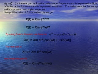

![(ii) Response to the following Input is given below:
(a) Vi (t)= 12volts
2(0) + 2
Vo (t)=[ ]x12
2(0) + 3
Vo (t)=8 volt
(b) Vi (t) =12e-3t
2(−3) + 2
Vo (t)=[ ]x12e −3t
2(−3) + 3
Vo (t)=16e −3t
(c) Vi (t) =12ej2t volt
2(2 j ) + 2
Vo (t)=[ ]12e j 2t
2(2 j ) + 3](https://image.slidesharecdn.com/concept-of-complex-frequency1-120418012713-phpapp01/85/Concept-of-complex-frequency-14-320.jpg)
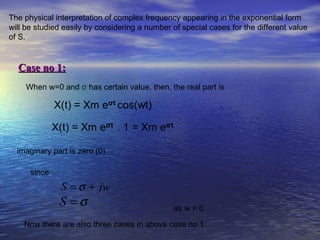
![4 j + 2 4 j −3
Vo (t)=[ x ]x12e j 2t
4 j +3 4 j −3
(d) Vi (t) =12e(-3+j2)t volt
2(−3 + j 2) + 2
Vo (t)=[ ]x12e ( −3+ j 2)t
2(−3 + j 2) + 3
Vo (t)=13.57<8.130o e( −3+ j 2)t
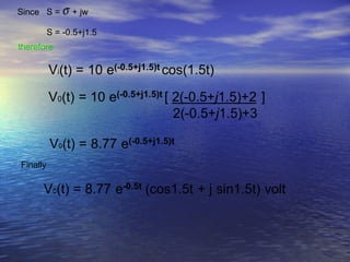
(e) Vi (t) =10e-0.5t cos(1.5t+30)
Since the given response voltage is of only real part & we know that
and we have given
Vi =10, σ =-0.5, w =1.5,](https://image.slidesharecdn.com/concept-of-complex-frequency1-120418012713-phpapp01/85/Concept-of-complex-frequency-15-320.jpg)


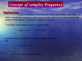
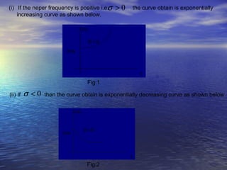
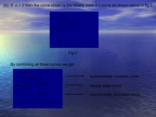
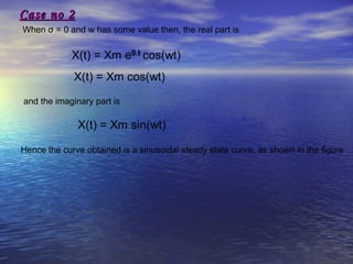
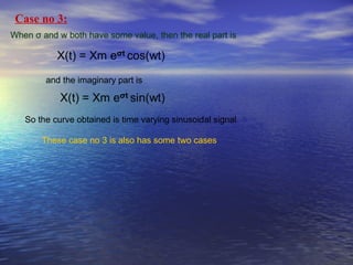
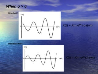
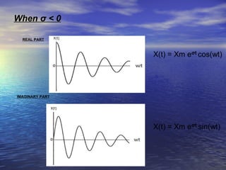
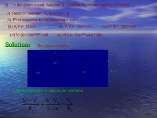
The document defines complex frequency as a type of frequency that depends on two parameters: σ, which controls the magnitude of the signal, and w, which controls the rotation. It presents the equation for a complex exponential signal and defines the terms. It then analyzes three cases of complex frequency: 1) when w = 0 and σ varies, 2) when σ = 0 and w varies, and 3) when both σ and w have values. The response of a circuit to various input signals is also analyzed using the complex frequency concept.


![Circuit Network Analysis - [Chapter5] Transfer function, frequency response, ...](https://cdn.slidesharecdn.com/ss_thumbnails/ch5-150613063859-lva1-app6891-thumbnail.jpg?width=640&height=640&fit=bounds)
![Circuit Network Analysis - [Chapter4] Laplace Transform](https://cdn.slidesharecdn.com/ss_thumbnails/ch4-150613063858-lva1-app6891-thumbnail.jpg?width=640&height=640&fit=bounds)


![Data Structures - Lecture 10 [Graphs]](https://cdn.slidesharecdn.com/ss_thumbnails/datastructures-lecture10graphs-150305004608-conversion-gate01-thumbnail.jpg?width=640&height=640&fit=bounds)


![Week 8 [compatibility mode]](https://cdn.slidesharecdn.com/ss_thumbnails/week8compatibilitymode-130213163443-phpapp01-thumbnail.jpg?width=640&height=640&fit=bounds)


