Downloaded 924 times
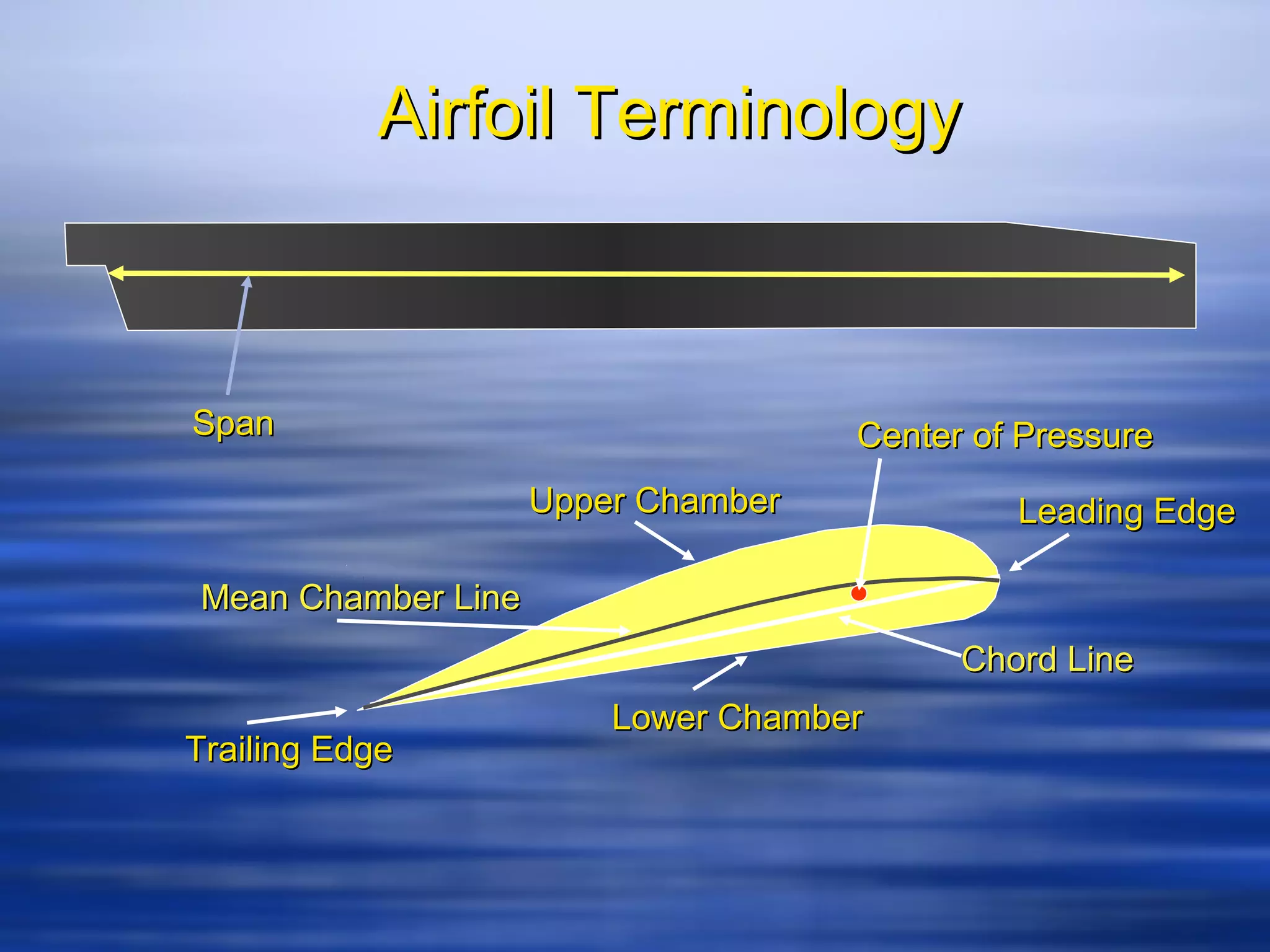

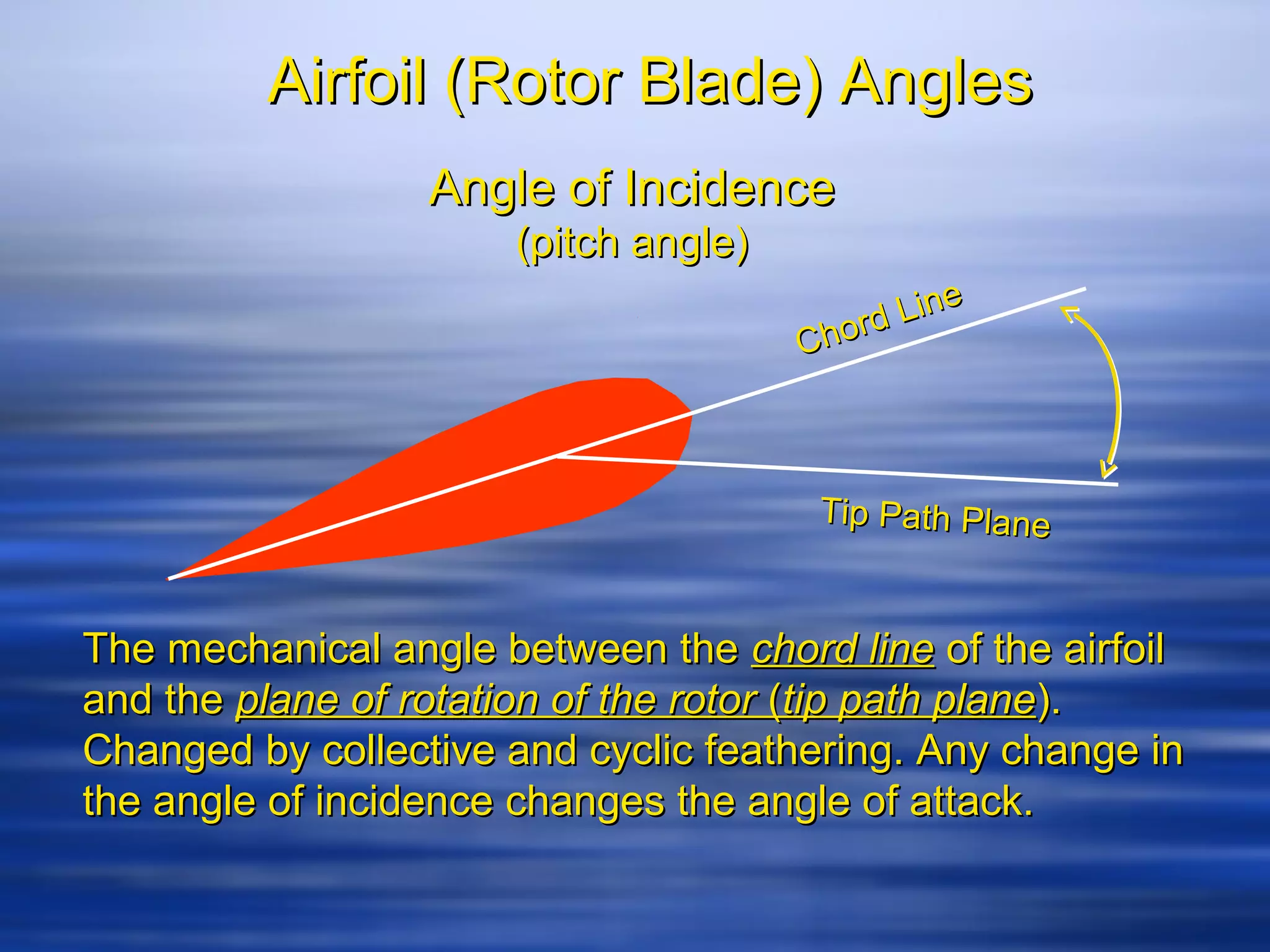

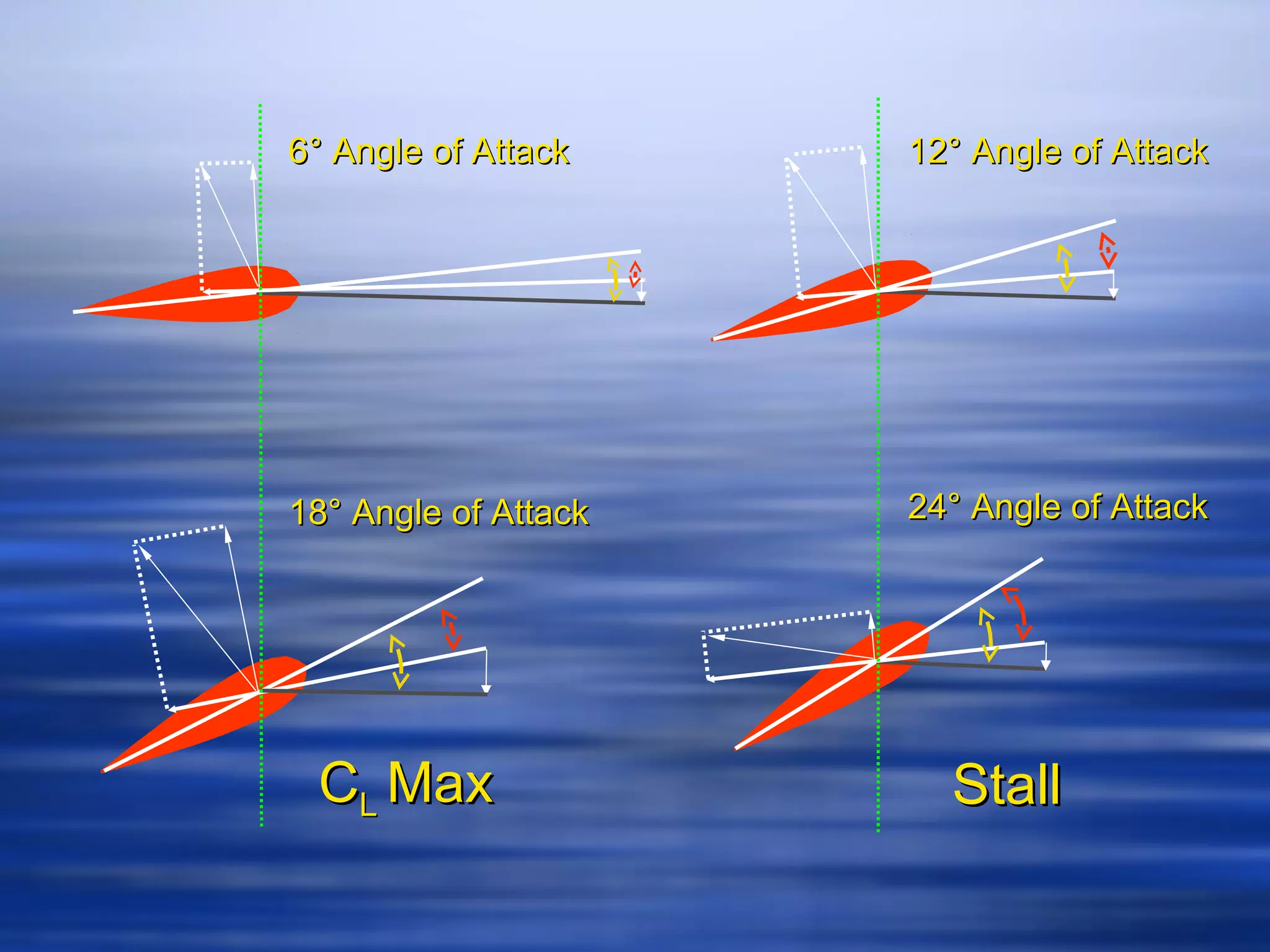

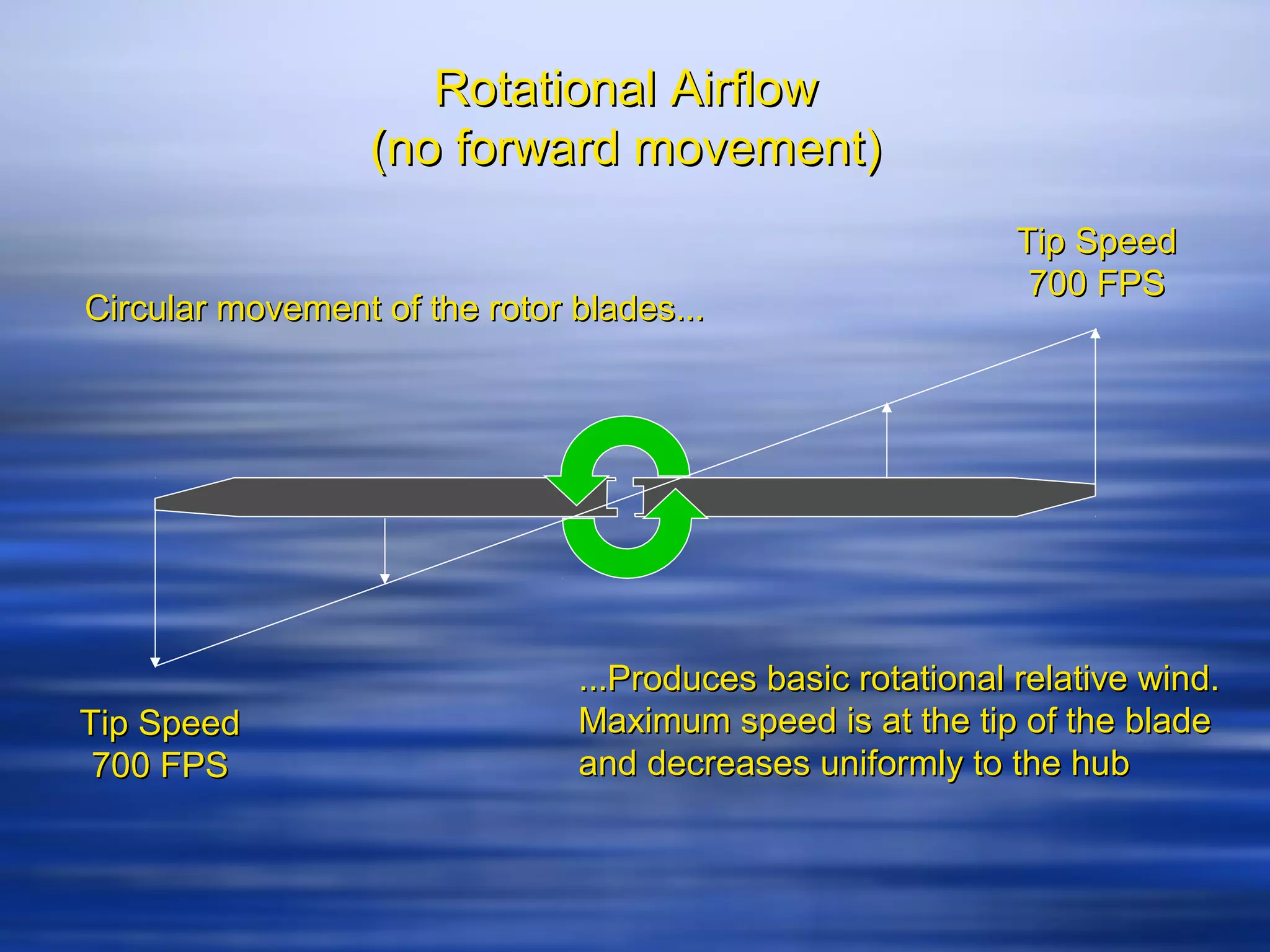


This document discusses airfoil and rotor blade terminology. It defines symmetrical and nonsymmetrical airfoils and their characteristics. It also defines the angles of incidence, attack, and describes how collective and cyclic feathering changes these angles to control the helicopter. Flapping, lead, and lag are also summarized as important motions of the rotor blades that help control the aircraft.