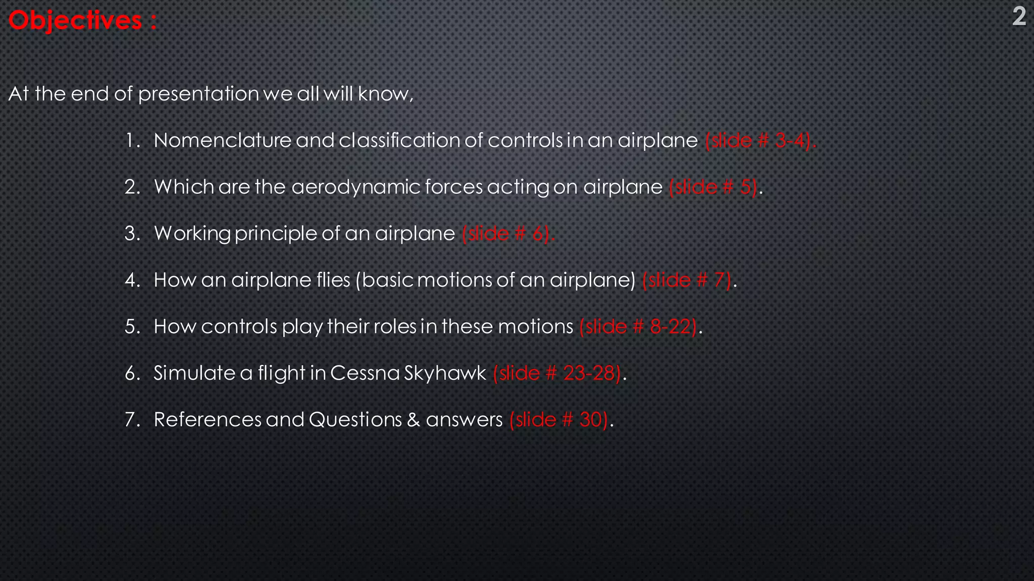
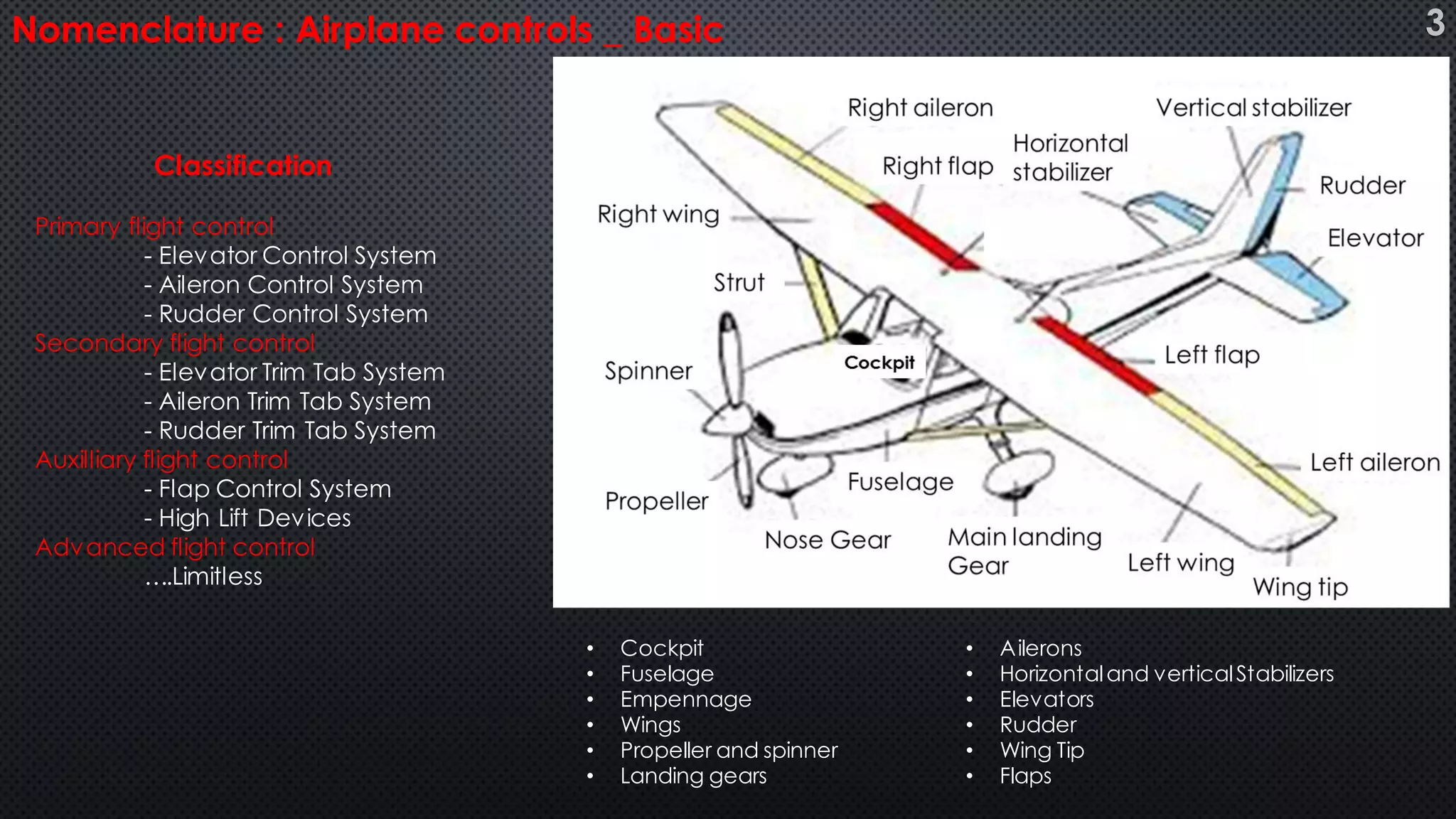
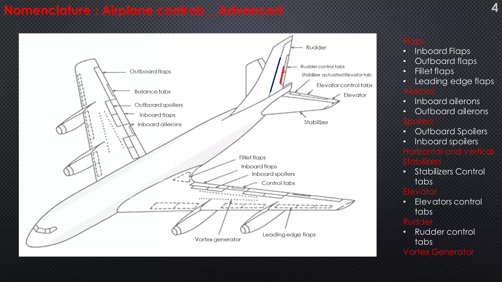
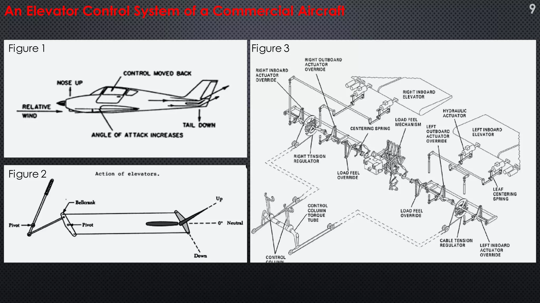
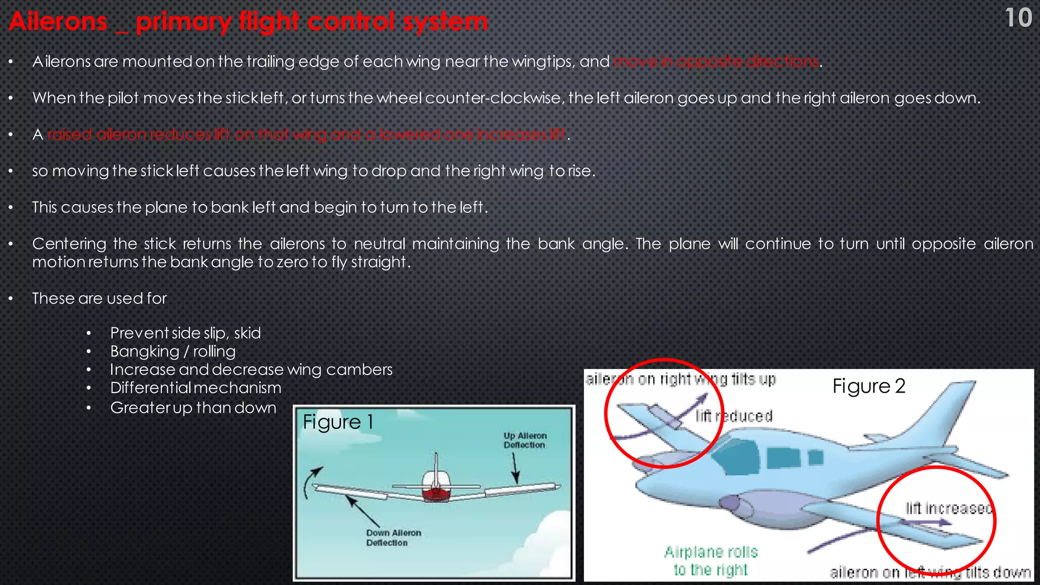
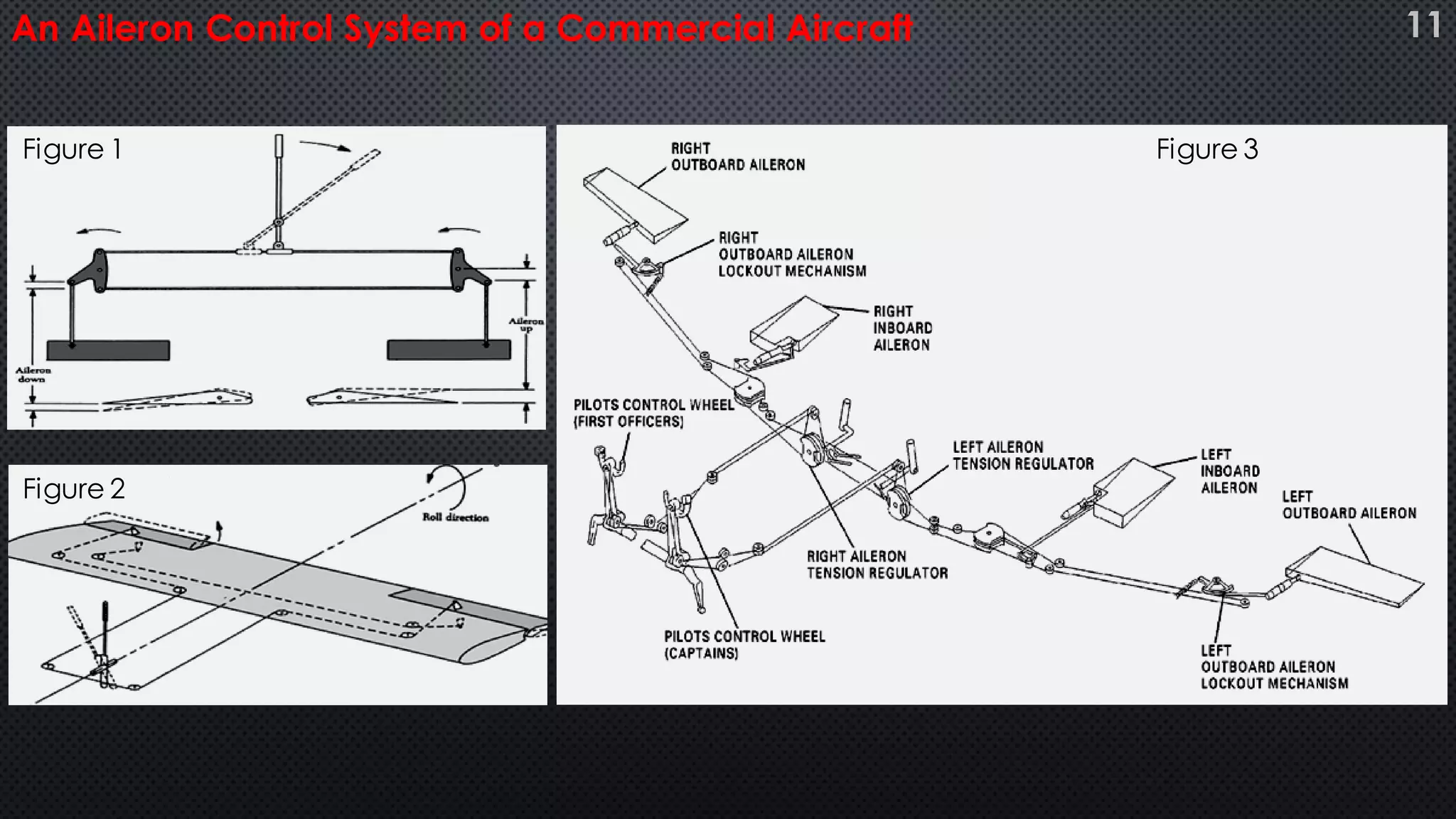
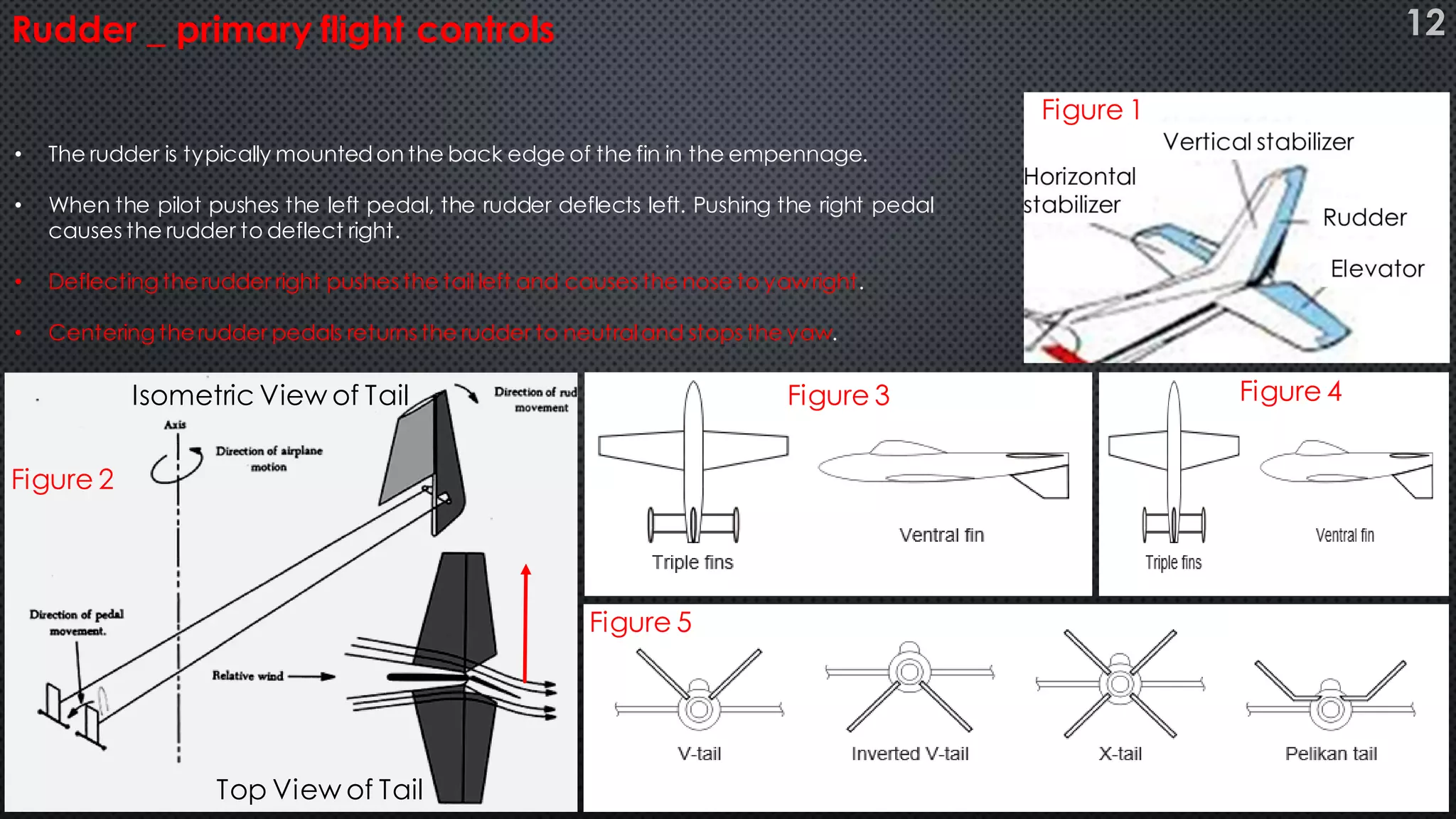
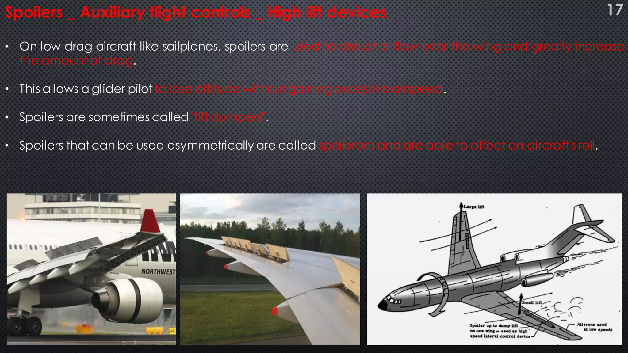
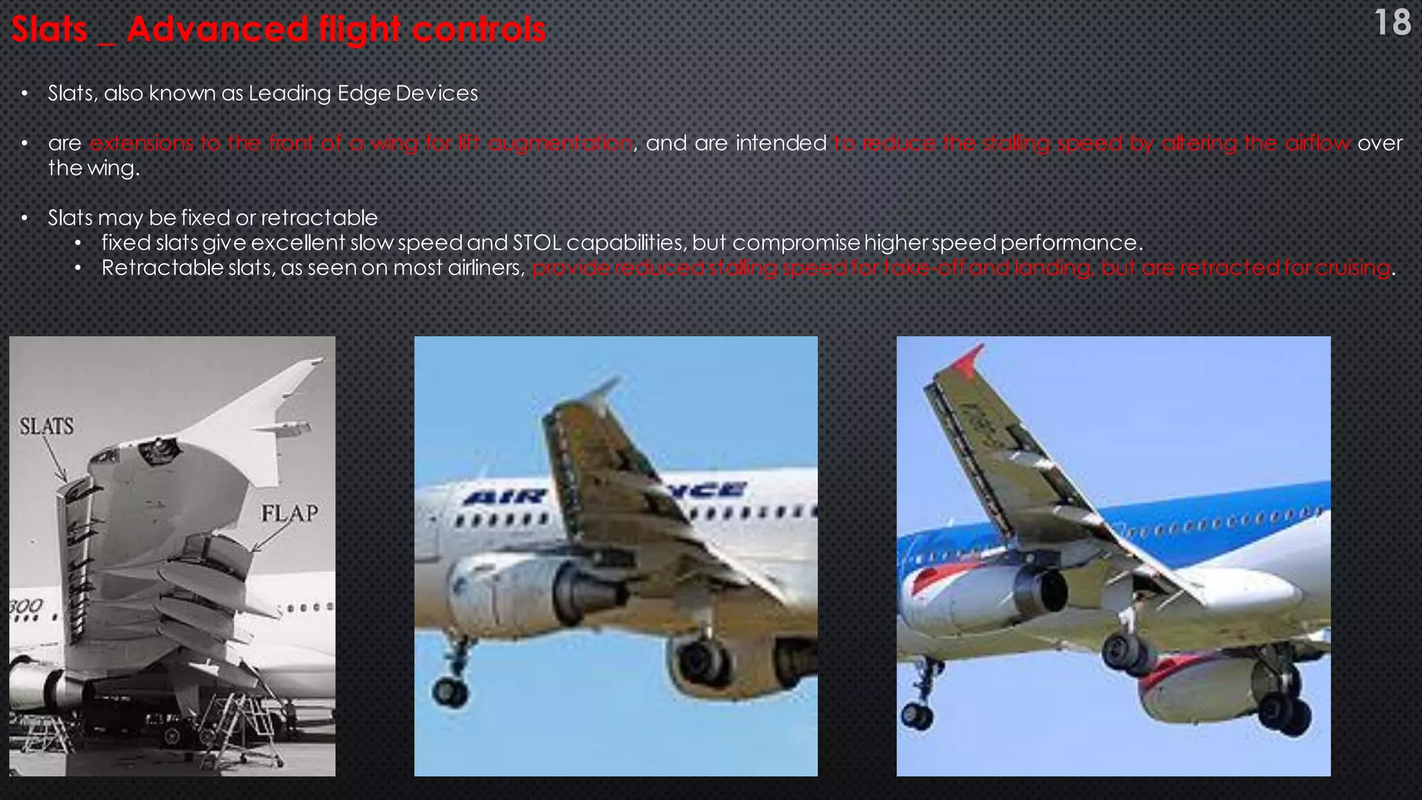
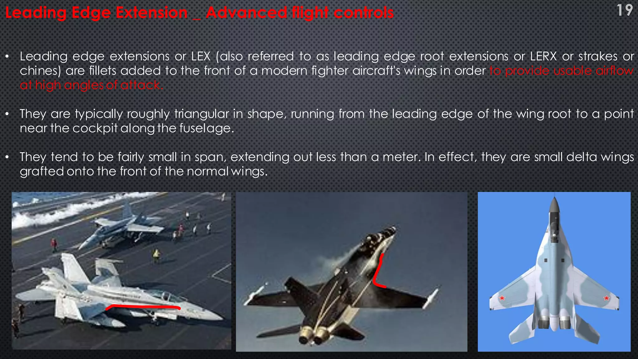
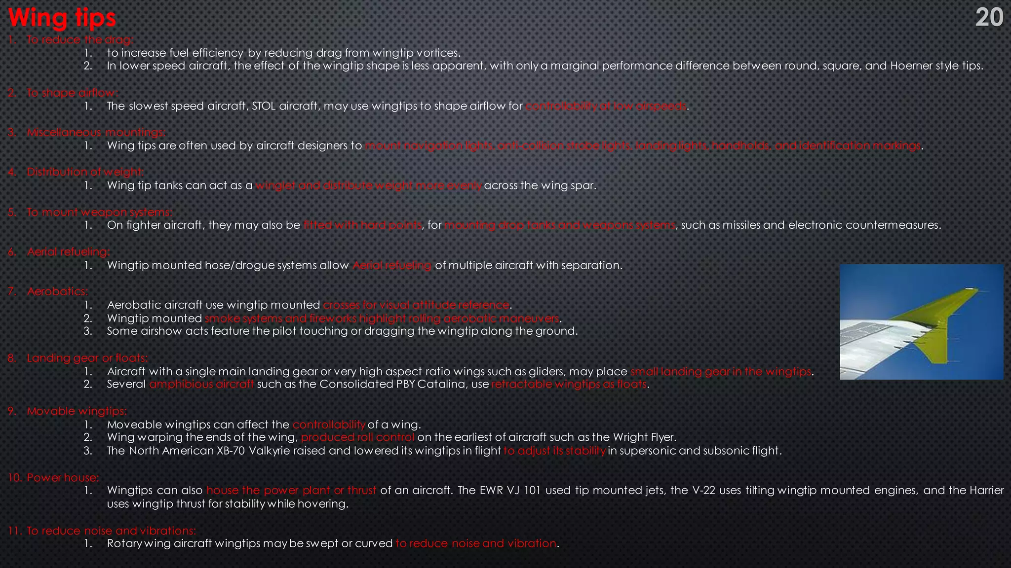
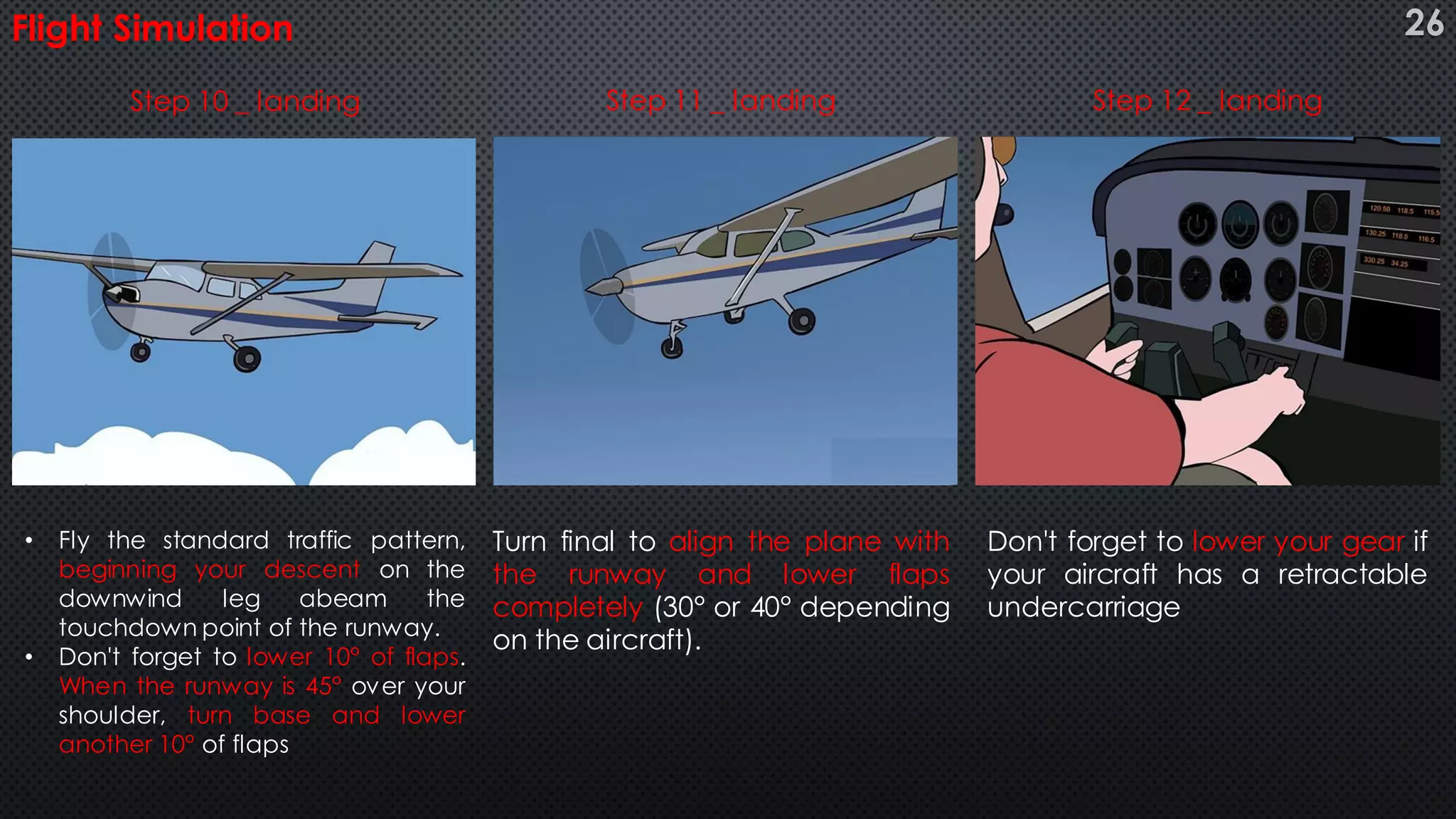
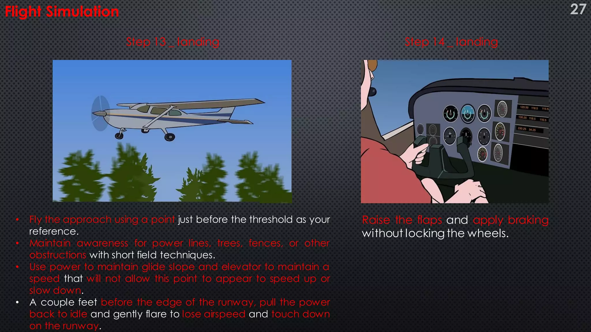
Slides : 30
Time : 10 minutesDate: 22nd January, 2015
Basics of Airplanes
Objectives :
At the end of presentation we all will know,
1. Nomenclature and classification of controls in an airplane (slide # 3-4).
2. Which are the aerodynamic forces acting on airplane (slide# 5).
3. Working principle of an airplane (slide # 6).
4. How an airplane flies (basicmotions of an airplane) (slide # 7).
5. How controls play their roles in these motions (slide # 8-22).
6. Simulate a flight in Cessna Skyhawk (slide # 23-28).
7. References and Questions & answers (slide # 30).
2
• Cockpit
• Fuselage
• Empennage
• Wings
• Propeller and spinner
• Landing gears
Nomenclature : Airplane controls _ Basic
Classification
Primary flight control
- Elevator Control System
- Aileron Control System
- Rudder Control System
Secondary flight control
- Elevator Trim Tab System
- Aileron Trim Tab System
- Rudder Trim Tab System
Auxilliary flight control
- Flap Control System
- High Lift Devices
Advanced flight control
….Limitless
• Ailerons
• Horizontaland verticalStabilizers
• Elevators
• Rudder
• Wing Tip
• Flaps
3
Nomenclature : Airplane controls _ Advanced
Flaps
• Inboard Flaps
• Outboard flaps
• Fillet flaps
• Leading edge flaps
Ailerons
• Inboard ailerons
• Outboard ailerons
Spoilers
• Outboard Spoilers
• Inboard spoilers
Horizontal and vertical
Stabilizers
• Stabilizers Control
tabs
Elevator
• Elevators control
tabs
Rudder
• Rudder control
tabs
Vortex Generator
4
Aerodynamic forces
Thrust Drag
Weight
Lift
For straight and control flight
Thrust = Drag
Lift = weight
Aerodynamic force created by
an airplane in order to
overcomedrag.
Means of thrust
• Propellers
• Jet Engines
• Rockets
Every object on earth has weight (including air).
Aerodynamicforce that holds an airplane in air.
Most of the lift required to keep the plane aloft is createdby the wings.
An aerodynamic forcethat
resist the motion of an object
Through a fluid (air and water
are fluids)
The amount of drag an
airplane creates depends on:
•Size and shape of the plane.
•Speedof an airplane.
•Density of the air.
5
Longerpath explanation:
• Particles split at the leading edge, and they come togetherat the trailing edge of the wing.
• Since the particles on toptravellonger distance in same amount of time, they must be traveling faster.
Bernoulli’s Theory:
• The speed of a fluid increases, its pressure decreases.
• Fastermoving air on the top creates a low pressure on the top.
• The low pressure on the top essentially “sucks”the plane wings upward.
Working Principle 6
Basic movements of an airplane
1. Pitch
2. Roll
3. yaw
7
• An elevatoris mounted on the back edge of the horizontalstabilizeron each side of the fin in the tail.
• They move upand down together.
• When the pilot pulls the stick backward, the elevators go up.
• Pushing the stick forward causes the elevators to go down. Raised elevators push down on the tail and cause the nose to pitch up.
• This makes the wings fly at a higher angle of attackwhich generates more lift and more drag.
• Many aircraft use a stabilizer — a moveable horizontalstabilizer— in place of an elevator.
• These are used to Dive or climb.
Elevator _ primary flight control system 8
An Elevator Control System of a Commercial Aircraft 9
Figure 1
Figure 2
Figure 3
• Ailerons are mounted on the trailing edge of each wing near the wingtips, and move in opposite directions.
• When the pilot moves the stickleft, or turns the wheel counter-clockwise, the left aileron goes up and the right aileron goes down.
• A raised aileron reduces lift on that wing and a lowered one increases lift.
• so moving the stick left causes theleft wing to drop and the right wing to rise.
• This causes the plane to bank left and begin to turn to the left.
• Centering the stick returns the ailerons to neutral maintaining the bank angle. The plane will continue to turn until opposite aileron
motion returns the bank angle to zero to fly straight.
• These are used for
• Prevent side slip, skid
• Bangking / rolling
• Increase anddecrease wing cambers
• Differentialmechanism
• Greaterup than down
Ailerons _ primary flight control system 10
Figure 1
Figure 2
An Aileron Control System of a Commercial Aircraft 11
Figure 1
Figure 2
Figure 3
• The rudder is typically mountedon the back edge of the fin in the empennage.
• When the pilot pushes the left pedal, the rudder deflects left. Pushing the right pedal
causes the rudder to deflect right.
• Deflecting therudder right pushes the tail left and causes the nose to yawright.
• Centering therudder pedals returns the rudder to neutraland stops the yaw.
Rudder _ primary flight controls
Top View of Tail
Isometric View of Tail
12
Figure 1
Figure 2
Figure 3 Figure 4
Figure 5
• Elevator trim balances the control force necessary to maintain the
aerodynamicdown force on the tail.
• When aircraft is flying, a lot of trim could be required to maintain the desired
angle of attack.
• This mainly applies to slow flight, where maintaining a nose-up attitude
requires a lot of trim.
• An important design parameter for aircraft is the stability of the aircraft
when trimmedfor levelflight.
• Any disturbances such as gusts or turbulence will be damped over a short
period of time and the aircraft will return to its levelflight trimmed airspeed.
Elevator trim tab system _ Secondary flight controls 13
• Trim doesn't only apply to the elevator, as there is also trim for the rudder and ailerons.
• The use of this is to counterthe effectsof slip stream, or to counterthe effectsof the centerof gravity being to one side.
• This can be caused by a larger weight on one side of the aircraft compared to the other, such as when one fuel tank has a lot more fuel
in it than the other, or when there are heavierpeople on one side of the aircraft than the other.
Rudder and Aileron trim tab system _ Secondary flight controls 14
• Flaps are hinged surfaces on the trailing edge of the wings of a fixed-wing
aircraft.
• As flaps are extended, thestalling speed of the aircraft is reduced.
• Flaps are also used on the leading edge of the wings of some high-speed jet
aircraft, where they may be called Kruegerflaps.
• Flaps increase the camberof the wing airfoil, thus raising the lift coefficient.
• This increase in lift coefficient allows the aircraft to generate a given amount of
lift with a slower speed.
• Therefore, extending the flaps will reduce the stalling speed of an aircraft.
• They also increase drag which helps to slow the aircraft.
Flaps _ Auxiliary flight controls 15
• Plain flap: rotates on a simple hinge.
• Split flap: upper and lower surfaces are separate, the lower
surface operates like a plain flap, but the upper surface stays
immobile or moves only slightly.
• Fowler flap: slides backwards before hinging downwards,
thereby increasing both camber and chord, creating a larger
wing surface bettertuned forlower speeds.
• Slotted flap: a slot (or gap) between the flap and the wing
enables high pressure air from below the wing to re-energize
the boundary layer over the flap. This helps the airflow to stay
attached to the flap, delaying the stall.
• Blown flaps: systems that blow engine air over the upper
surface of the flap at certain angles to improve lift
characteristics.
• Kruegerflap: hinged flap on the leading edge.
Types of flap systems: 16
• On low drag aircraft like sailplanes, spoilers are used to disrupt airflow over the wing and greatly increase
the amount of drag.
• This allows a glider pilotto lose altitude without gaining excessiveairspeed.
• Spoilers are sometimes called "lift dumpers".
• Spoilers that can be used asymmetrically are called spoilerons and are able to affect an aircraft's roll.
Spoilers _ Auxiliary flight controls _ High lift devices 17
• Slats, also known as Leading Edge Devices
• are extensions to the front of a wing for lift augmentation, and are intended to reduce the stalling speed by altering the airflow over
the wing.
• Slats may be fixed or retractable
• fixed slats give excellent slow speed and STOL capabilities, but compromisehigherspeed performance.
• Retractable slats, as seen on most airliners, provide reduced stalling speedfor take-offand landing, but are retracted forcruising.
Slats _ Advanced flight controls 18
• Leading edge extensions or LEX (also referred to as leading edge root extensions or LERX or strakes or
chines) are fillets added to the front of a modern fighter aircraft's wings in order to provide usable airflow
at high angles of attack.
• They are typically roughly triangular in shape, running from the leading edge of the wing root to a point
near the cockpit along the fuselage.
• They tend to be fairly small in span, extending out less than a meter. In effect, they are small delta wings
grafted onto the front of the normal wings.
Leading Edge Extension _ Advanced flight controls 19
1. To reduce the drag:
1. to increase fuel efficiency by reducing drag from wingtip vortices.
2. In lower speed aircraft, the effect of the wingtip shape is less apparent, with only a marginal performance difference between round, square, and Hoerner style tips.
2. To shape airflow:
1. The slowest speed aircraft, STOL aircraft, may use wingtips to shape airflow for controllability at low airspeeds.
3. Miscellaneous mountings:
1. Wing tips are often used by aircraft designers to mount navigation lights, anti-collision strobe lights, landing lights, handholds, and identification markings.
4. Distribution of weight:
1. Wing tip tanks can act as a winglet and distribute weight more evenly across the wing spar.
5. To mount weapon systems:
1. On fighter aircraft, they may also be fitted with hard points, for mounting drop tanks and weapons systems, such as missiles and electronic countermeasures.
6. Aerial refueling:
1. Wingtip mounted hose/drogue systems allow Aerial refueling of multiple aircraft with separation.
7. Aerobatics:
1. Aerobatic aircraft use wingtip mounted crosses for visual attitude reference.
2. Wingtip mounted smoke systems and fireworks highlight rolling aerobatic maneuvers.
3. Some airshow acts feature the pilot touching or dragging the wingtip along the ground.
8. Landing gear or floats:
1. Aircraft with a single main landing gear or very high aspect ratio wings such as gliders, may place small landing gear in the wingtips.
2. Several amphibious aircraft such as the Consolidated PBY Catalina, use retractable wingtips as floats.
9. Movable wingtips:
1. Moveable wingtips can affect the controllability of a wing.
2. Wing warping the ends of the wing, produced roll control on the earliest of aircraft such as the Wright Flyer.
3. The North American XB-70 Valkyrie raised and lowered its wingtips in flight to adjust its stability in supersonic and subsonic flight.
10. Power house:
1. Wingtips can also house the power plant or thrust of an aircraft. The EWR VJ 101 used tip mounted jets, the V-22 uses tilting wingtip mounted engines, and the Harrier
uses wingtip thrust for stability while hovering.
11. To reduce noise and vibrations:
1. Rotary wing aircraft wingtips may be swept or curved to reduce noise and vibration.
Wing tips 20
Wing Tips 21
• To reduce the drag caused by
supersonic flow over portion of
the wing, small airfoils called
vortex generators are installed
perpendicular to the surface of
the wing.
• Mounted in complementary
pairs.
• This causes the vortices being
developed to add one another,
thus increasing the effect.
• On some aircraft, fences are
installed on the wings and
elevators. This gives more
stability and control of the
aircraft, reduces buffeting, and
reduces high-speed stall
characteristics.
Wing vortex generators 22
Flight Simulation
Obtain takeoff clearance from
the tower or announce your
intentions on the Common
Traffic Advisory Frequency
(CTAF), taxi onto the runway and
align the plane with the center-
line.
If acceleration from the hold
short line is not possible, taxi to
the takeoff end. Apply your toe
brakes and leave the flaps in 0°
position
Smoothly apply full power and
release the brakes once the RPM
is in the green arc.
Step 1 _ takeoff Step 2 _ takeoff Step 3 _ takeoff
23
Flight Simulation
Keep the plane centered with
the rudder pedals.
By the point of time you reach
about 20% below rotation speed,
set the flaps to the takeoff
position.
Once rotation speed is reached
gently pull back on the yoke .
This speed, called Vr, can be
found in the Pilot's Operating
Handbook (POH).
Step 4 _ takeoff Step 5 _ takeoff Step 6 _ takeoff
24
Flight Simulation
If the density at altitude and
gross weight are both relevant,
climb at the best angle of climb
speed, Vx, which can also be
found in the POH. Get Flaps to
zero degrees again and use
elevators to control altitude.
To turn an airplane, move the
rudder in desired direction along
with ailerons at relevant
elevation. (Relation can be
found in POH)
Enter the pattern as you would
at any airport after contacting
the tower or announcing your
position on the CTAF.
Step 7 _ takeoff Step 8 _ turning Step 9 _ landing
25
Flight Simulation
Don't forget to lower your gear if
your aircraft has a retractable
undercarriage
• Fly the standard traffic pattern,
beginning your descent on the
downwind leg abeam the
touchdown point of the runway.
• Don't forget to lower 10° of flaps.
When the runway is 45° over your
shoulder, turn base and lower
another 10° of flaps
Turn final to align the plane with
the runway and lower flaps
completely (30° or 40° depending
on the aircraft).
Step 10 _ landing Step 11 _ landing Step 12 _ landing
26
Flight Simulation
• Fly the approach using a point just before the threshold as your
reference.
• Maintain awareness for power lines, trees, fences, or other
obstructions with short field techniques.
• Use power to maintain glide slope and elevator to maintain a
speed that will not allow this point to appear to speed up or
slow down.
• A couple feet before the edge of the runway, pull the power
back to idle and gently flare to lose airspeed and touch down
on the runway.
Raise the flaps and apply braking
without locking the wheels.
Step 13 _ landing Step 14 _ landing
27
Flight Simulation
Deploy spoilers to reduce the
airspeed before reaching the
safe limit of full braking speed.
Apply full back pressure on the
yoke to keep the weight on the
main gear.
Exit the runway to make room for
other aircraft traffic.
Step 15 _ landing Step 16 _ landing Step 17 _ landing
28
Now we all know
1. Basic nomenclature and classification of controls in an airplane.
1. primary , Secondary, Auxiliary, Advanced
2. aerodynamicforces actingon airplane.
1. Lift, Weight, Thrust, Drag
3. Working principle of an airplane.
1. Longer path explanation andBernoulli's theorem
4. How an airplane flies (basicmotions of an airplane)
1. Pitch, roll, yaw
5. How controls play the role in these motions
1. Elevators, Ailerons, Rudder
2. Trimtab systems
3. Flaps, spoilers
4. Slats, leading edge extensions, wing tips, vortex generators
6. We Simulated a flight.
1. Takeoff, turning, landing
29Conclusion
References
1. http://functionspace.org
2. http://www.aerospaceweb.org
3. http://selair.selkirk.bc.ca/training/aerodynamics
4. http://www.nomenclaturo.com
5. http://en.wikipedia.org
6. https://www.google.co.in/imghp
7. http://www.wikihow.com
8. Games : Crimson skies, pacific navy fighters, Air navy fighters, Rortos Carrier Landing, V22 Osprey.
Questions
30

Basics of airplanes

  • 1.
    Slides : 30 Time: 10 minutesDate: 22nd January, 2015 Basics of Airplanes
  • 2.
    Objectives : At theend of presentation we all will know, 1. Nomenclature and classification of controls in an airplane (slide # 3-4). 2. Which are the aerodynamic forces acting on airplane (slide# 5). 3. Working principle of an airplane (slide # 6). 4. How an airplane flies (basicmotions of an airplane) (slide # 7). 5. How controls play their roles in these motions (slide # 8-22). 6. Simulate a flight in Cessna Skyhawk (slide # 23-28). 7. References and Questions & answers (slide # 30). 2
  • 3.
    • Cockpit • Fuselage •Empennage • Wings • Propeller and spinner • Landing gears Nomenclature : Airplane controls _ Basic Classification Primary flight control - Elevator Control System - Aileron Control System - Rudder Control System Secondary flight control - Elevator Trim Tab System - Aileron Trim Tab System - Rudder Trim Tab System Auxilliary flight control - Flap Control System - High Lift Devices Advanced flight control ….Limitless • Ailerons • Horizontaland verticalStabilizers • Elevators • Rudder • Wing Tip • Flaps 3
  • 4.
    Nomenclature : Airplanecontrols _ Advanced Flaps • Inboard Flaps • Outboard flaps • Fillet flaps • Leading edge flaps Ailerons • Inboard ailerons • Outboard ailerons Spoilers • Outboard Spoilers • Inboard spoilers Horizontal and vertical Stabilizers • Stabilizers Control tabs Elevator • Elevators control tabs Rudder • Rudder control tabs Vortex Generator 4
  • 5.
    Aerodynamic forces Thrust Drag Weight Lift Forstraight and control flight Thrust = Drag Lift = weight Aerodynamic force created by an airplane in order to overcomedrag. Means of thrust • Propellers • Jet Engines • Rockets Every object on earth has weight (including air). Aerodynamicforce that holds an airplane in air. Most of the lift required to keep the plane aloft is createdby the wings. An aerodynamic forcethat resist the motion of an object Through a fluid (air and water are fluids) The amount of drag an airplane creates depends on: •Size and shape of the plane. •Speedof an airplane. •Density of the air. 5
  • 6.
    Longerpath explanation: • Particlessplit at the leading edge, and they come togetherat the trailing edge of the wing. • Since the particles on toptravellonger distance in same amount of time, they must be traveling faster. Bernoulli’s Theory: • The speed of a fluid increases, its pressure decreases. • Fastermoving air on the top creates a low pressure on the top. • The low pressure on the top essentially “sucks”the plane wings upward. Working Principle 6
  • 7.
    Basic movements ofan airplane 1. Pitch 2. Roll 3. yaw 7
  • 8.
    • An elevatorismounted on the back edge of the horizontalstabilizeron each side of the fin in the tail. • They move upand down together. • When the pilot pulls the stick backward, the elevators go up. • Pushing the stick forward causes the elevators to go down. Raised elevators push down on the tail and cause the nose to pitch up. • This makes the wings fly at a higher angle of attackwhich generates more lift and more drag. • Many aircraft use a stabilizer — a moveable horizontalstabilizer— in place of an elevator. • These are used to Dive or climb. Elevator _ primary flight control system 8
  • 9.
    An Elevator ControlSystem of a Commercial Aircraft 9 Figure 1 Figure 2 Figure 3
  • 10.
    • Ailerons aremounted on the trailing edge of each wing near the wingtips, and move in opposite directions. • When the pilot moves the stickleft, or turns the wheel counter-clockwise, the left aileron goes up and the right aileron goes down. • A raised aileron reduces lift on that wing and a lowered one increases lift. • so moving the stick left causes theleft wing to drop and the right wing to rise. • This causes the plane to bank left and begin to turn to the left. • Centering the stick returns the ailerons to neutral maintaining the bank angle. The plane will continue to turn until opposite aileron motion returns the bank angle to zero to fly straight. • These are used for • Prevent side slip, skid • Bangking / rolling • Increase anddecrease wing cambers • Differentialmechanism • Greaterup than down Ailerons _ primary flight control system 10 Figure 1 Figure 2
  • 11.
    An Aileron ControlSystem of a Commercial Aircraft 11 Figure 1 Figure 2 Figure 3
  • 12.
    • The rudderis typically mountedon the back edge of the fin in the empennage. • When the pilot pushes the left pedal, the rudder deflects left. Pushing the right pedal causes the rudder to deflect right. • Deflecting therudder right pushes the tail left and causes the nose to yawright. • Centering therudder pedals returns the rudder to neutraland stops the yaw. Rudder _ primary flight controls Top View of Tail Isometric View of Tail 12 Figure 1 Figure 2 Figure 3 Figure 4 Figure 5
  • 13.
    • Elevator trimbalances the control force necessary to maintain the aerodynamicdown force on the tail. • When aircraft is flying, a lot of trim could be required to maintain the desired angle of attack. • This mainly applies to slow flight, where maintaining a nose-up attitude requires a lot of trim. • An important design parameter for aircraft is the stability of the aircraft when trimmedfor levelflight. • Any disturbances such as gusts or turbulence will be damped over a short period of time and the aircraft will return to its levelflight trimmed airspeed. Elevator trim tab system _ Secondary flight controls 13
  • 14.
    • Trim doesn'tonly apply to the elevator, as there is also trim for the rudder and ailerons. • The use of this is to counterthe effectsof slip stream, or to counterthe effectsof the centerof gravity being to one side. • This can be caused by a larger weight on one side of the aircraft compared to the other, such as when one fuel tank has a lot more fuel in it than the other, or when there are heavierpeople on one side of the aircraft than the other. Rudder and Aileron trim tab system _ Secondary flight controls 14
  • 15.
    • Flaps arehinged surfaces on the trailing edge of the wings of a fixed-wing aircraft. • As flaps are extended, thestalling speed of the aircraft is reduced. • Flaps are also used on the leading edge of the wings of some high-speed jet aircraft, where they may be called Kruegerflaps. • Flaps increase the camberof the wing airfoil, thus raising the lift coefficient. • This increase in lift coefficient allows the aircraft to generate a given amount of lift with a slower speed. • Therefore, extending the flaps will reduce the stalling speed of an aircraft. • They also increase drag which helps to slow the aircraft. Flaps _ Auxiliary flight controls 15
  • 16.
    • Plain flap:rotates on a simple hinge. • Split flap: upper and lower surfaces are separate, the lower surface operates like a plain flap, but the upper surface stays immobile or moves only slightly. • Fowler flap: slides backwards before hinging downwards, thereby increasing both camber and chord, creating a larger wing surface bettertuned forlower speeds. • Slotted flap: a slot (or gap) between the flap and the wing enables high pressure air from below the wing to re-energize the boundary layer over the flap. This helps the airflow to stay attached to the flap, delaying the stall. • Blown flaps: systems that blow engine air over the upper surface of the flap at certain angles to improve lift characteristics. • Kruegerflap: hinged flap on the leading edge. Types of flap systems: 16
  • 17.
    • On lowdrag aircraft like sailplanes, spoilers are used to disrupt airflow over the wing and greatly increase the amount of drag. • This allows a glider pilotto lose altitude without gaining excessiveairspeed. • Spoilers are sometimes called "lift dumpers". • Spoilers that can be used asymmetrically are called spoilerons and are able to affect an aircraft's roll. Spoilers _ Auxiliary flight controls _ High lift devices 17
  • 18.
    • Slats, alsoknown as Leading Edge Devices • are extensions to the front of a wing for lift augmentation, and are intended to reduce the stalling speed by altering the airflow over the wing. • Slats may be fixed or retractable • fixed slats give excellent slow speed and STOL capabilities, but compromisehigherspeed performance. • Retractable slats, as seen on most airliners, provide reduced stalling speedfor take-offand landing, but are retracted forcruising. Slats _ Advanced flight controls 18
  • 19.
    • Leading edgeextensions or LEX (also referred to as leading edge root extensions or LERX or strakes or chines) are fillets added to the front of a modern fighter aircraft's wings in order to provide usable airflow at high angles of attack. • They are typically roughly triangular in shape, running from the leading edge of the wing root to a point near the cockpit along the fuselage. • They tend to be fairly small in span, extending out less than a meter. In effect, they are small delta wings grafted onto the front of the normal wings. Leading Edge Extension _ Advanced flight controls 19
  • 20.
    1. To reducethe drag: 1. to increase fuel efficiency by reducing drag from wingtip vortices. 2. In lower speed aircraft, the effect of the wingtip shape is less apparent, with only a marginal performance difference between round, square, and Hoerner style tips. 2. To shape airflow: 1. The slowest speed aircraft, STOL aircraft, may use wingtips to shape airflow for controllability at low airspeeds. 3. Miscellaneous mountings: 1. Wing tips are often used by aircraft designers to mount navigation lights, anti-collision strobe lights, landing lights, handholds, and identification markings. 4. Distribution of weight: 1. Wing tip tanks can act as a winglet and distribute weight more evenly across the wing spar. 5. To mount weapon systems: 1. On fighter aircraft, they may also be fitted with hard points, for mounting drop tanks and weapons systems, such as missiles and electronic countermeasures. 6. Aerial refueling: 1. Wingtip mounted hose/drogue systems allow Aerial refueling of multiple aircraft with separation. 7. Aerobatics: 1. Aerobatic aircraft use wingtip mounted crosses for visual attitude reference. 2. Wingtip mounted smoke systems and fireworks highlight rolling aerobatic maneuvers. 3. Some airshow acts feature the pilot touching or dragging the wingtip along the ground. 8. Landing gear or floats: 1. Aircraft with a single main landing gear or very high aspect ratio wings such as gliders, may place small landing gear in the wingtips. 2. Several amphibious aircraft such as the Consolidated PBY Catalina, use retractable wingtips as floats. 9. Movable wingtips: 1. Moveable wingtips can affect the controllability of a wing. 2. Wing warping the ends of the wing, produced roll control on the earliest of aircraft such as the Wright Flyer. 3. The North American XB-70 Valkyrie raised and lowered its wingtips in flight to adjust its stability in supersonic and subsonic flight. 10. Power house: 1. Wingtips can also house the power plant or thrust of an aircraft. The EWR VJ 101 used tip mounted jets, the V-22 uses tilting wingtip mounted engines, and the Harrier uses wingtip thrust for stability while hovering. 11. To reduce noise and vibrations: 1. Rotary wing aircraft wingtips may be swept or curved to reduce noise and vibration. Wing tips 20
  • 21.
  • 22.
    • To reducethe drag caused by supersonic flow over portion of the wing, small airfoils called vortex generators are installed perpendicular to the surface of the wing. • Mounted in complementary pairs. • This causes the vortices being developed to add one another, thus increasing the effect. • On some aircraft, fences are installed on the wings and elevators. This gives more stability and control of the aircraft, reduces buffeting, and reduces high-speed stall characteristics. Wing vortex generators 22
  • 23.
    Flight Simulation Obtain takeoffclearance from the tower or announce your intentions on the Common Traffic Advisory Frequency (CTAF), taxi onto the runway and align the plane with the center- line. If acceleration from the hold short line is not possible, taxi to the takeoff end. Apply your toe brakes and leave the flaps in 0° position Smoothly apply full power and release the brakes once the RPM is in the green arc. Step 1 _ takeoff Step 2 _ takeoff Step 3 _ takeoff 23
  • 24.
    Flight Simulation Keep theplane centered with the rudder pedals. By the point of time you reach about 20% below rotation speed, set the flaps to the takeoff position. Once rotation speed is reached gently pull back on the yoke . This speed, called Vr, can be found in the Pilot's Operating Handbook (POH). Step 4 _ takeoff Step 5 _ takeoff Step 6 _ takeoff 24
  • 25.
    Flight Simulation If thedensity at altitude and gross weight are both relevant, climb at the best angle of climb speed, Vx, which can also be found in the POH. Get Flaps to zero degrees again and use elevators to control altitude. To turn an airplane, move the rudder in desired direction along with ailerons at relevant elevation. (Relation can be found in POH) Enter the pattern as you would at any airport after contacting the tower or announcing your position on the CTAF. Step 7 _ takeoff Step 8 _ turning Step 9 _ landing 25
  • 26.
    Flight Simulation Don't forgetto lower your gear if your aircraft has a retractable undercarriage • Fly the standard traffic pattern, beginning your descent on the downwind leg abeam the touchdown point of the runway. • Don't forget to lower 10° of flaps. When the runway is 45° over your shoulder, turn base and lower another 10° of flaps Turn final to align the plane with the runway and lower flaps completely (30° or 40° depending on the aircraft). Step 10 _ landing Step 11 _ landing Step 12 _ landing 26
  • 27.
    Flight Simulation • Flythe approach using a point just before the threshold as your reference. • Maintain awareness for power lines, trees, fences, or other obstructions with short field techniques. • Use power to maintain glide slope and elevator to maintain a speed that will not allow this point to appear to speed up or slow down. • A couple feet before the edge of the runway, pull the power back to idle and gently flare to lose airspeed and touch down on the runway. Raise the flaps and apply braking without locking the wheels. Step 13 _ landing Step 14 _ landing 27
  • 28.
    Flight Simulation Deploy spoilersto reduce the airspeed before reaching the safe limit of full braking speed. Apply full back pressure on the yoke to keep the weight on the main gear. Exit the runway to make room for other aircraft traffic. Step 15 _ landing Step 16 _ landing Step 17 _ landing 28
  • 29.
    Now we allknow 1. Basic nomenclature and classification of controls in an airplane. 1. primary , Secondary, Auxiliary, Advanced 2. aerodynamicforces actingon airplane. 1. Lift, Weight, Thrust, Drag 3. Working principle of an airplane. 1. Longer path explanation andBernoulli's theorem 4. How an airplane flies (basicmotions of an airplane) 1. Pitch, roll, yaw 5. How controls play the role in these motions 1. Elevators, Ailerons, Rudder 2. Trimtab systems 3. Flaps, spoilers 4. Slats, leading edge extensions, wing tips, vortex generators 6. We Simulated a flight. 1. Takeoff, turning, landing 29Conclusion
  • 30.
    References 1. http://functionspace.org 2. http://www.aerospaceweb.org 3.http://selair.selkirk.bc.ca/training/aerodynamics 4. http://www.nomenclaturo.com 5. http://en.wikipedia.org 6. https://www.google.co.in/imghp 7. http://www.wikihow.com 8. Games : Crimson skies, pacific navy fighters, Air navy fighters, Rortos Carrier Landing, V22 Osprey. Questions 30