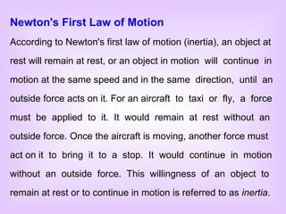
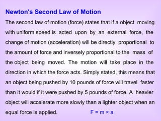
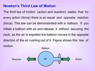
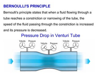
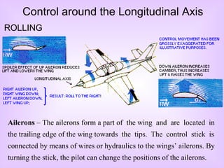
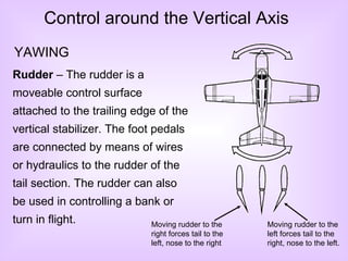
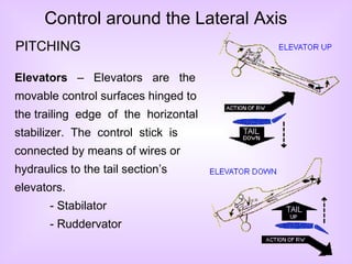
Downloaded 7,000 times

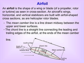
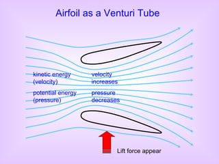
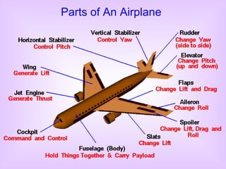
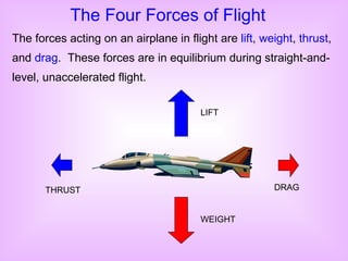
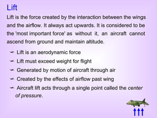
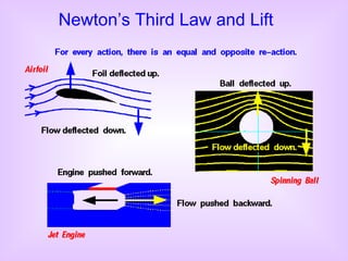
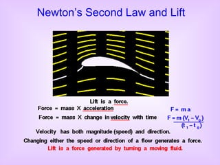
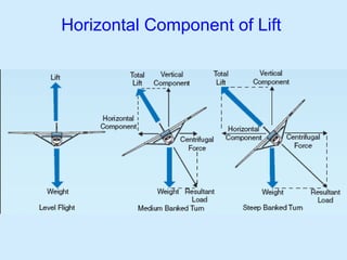
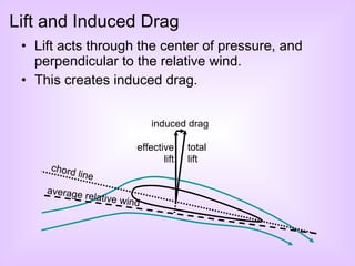
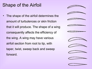
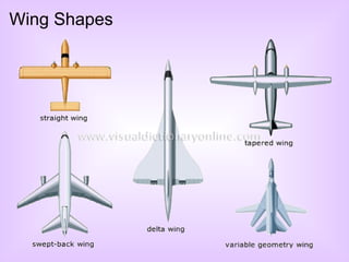
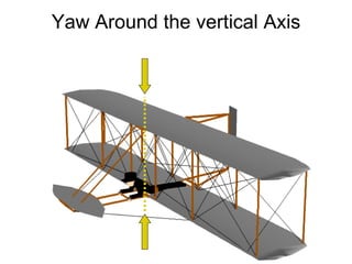
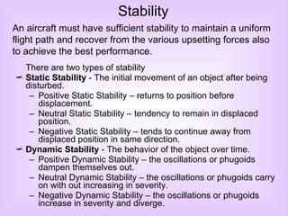


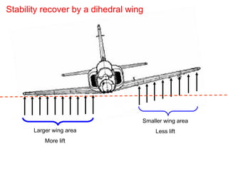
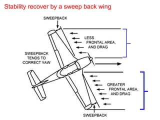


This document provides an overview of basic aerodynamic principles and aircraft flight theory. It covers key topics such as the atmosphere, Newton's laws of motion, Bernoulli's principle, airfoils, the four forces of flight, stability and control surfaces. The presentation introduces fundamental concepts including pressure, density, humidity, inertia, lift, drag, thrust, weight, angles of attack and incidence, and the three axes of movement. It also explains how stability is achieved through aircraft design elements like dihedral wings, sweepback, and keel effect.