Download to read offline


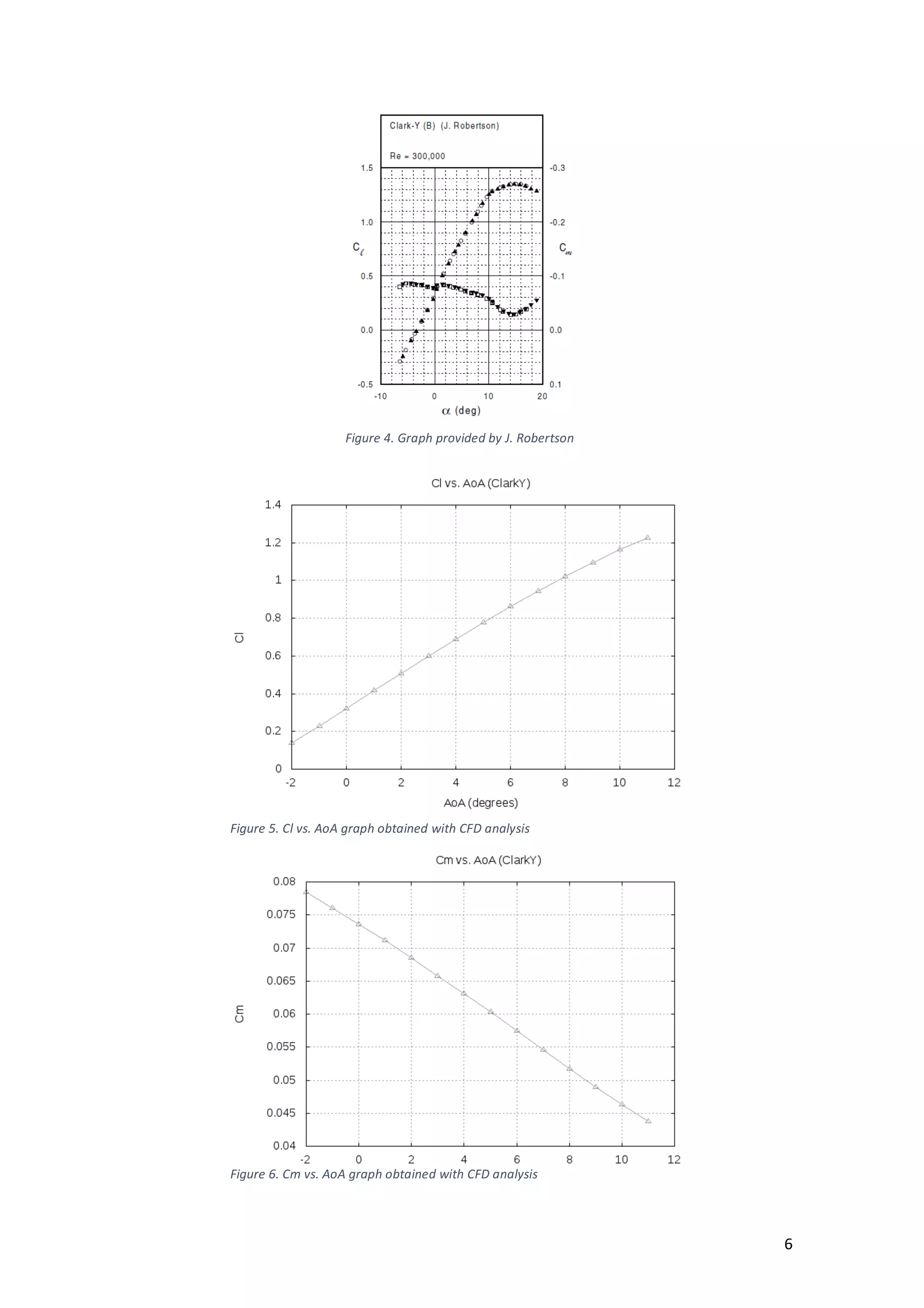


The document details a study on the aerodynamic analysis of a motoglider, focusing on airfoil performance and computational fluid dynamics (CFD) simulations. It includes an introduction, airfoil analysis, and airplane study, detailing the methodology, results, and conclusions drawn from comparing simulated and experimental data. The findings indicate an overall good match in lift coefficients, particularly in the linear region, but highlight issues with drag coefficients and the need for better turbulence modeling.


