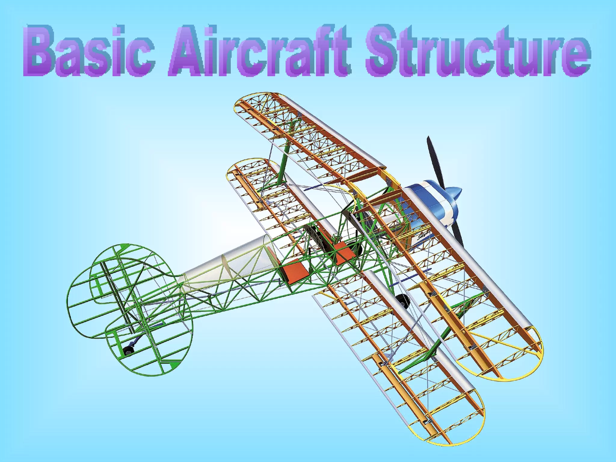
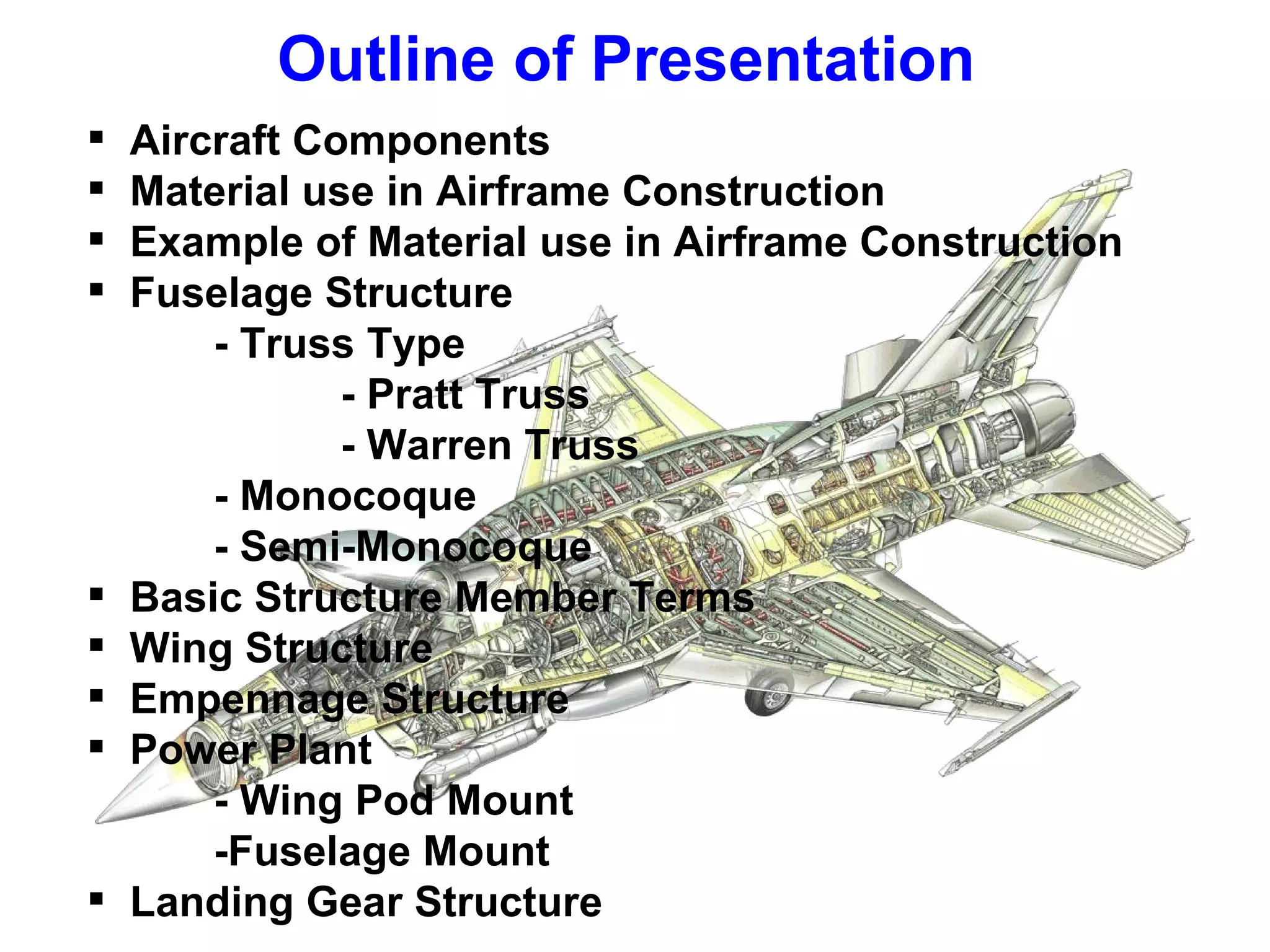
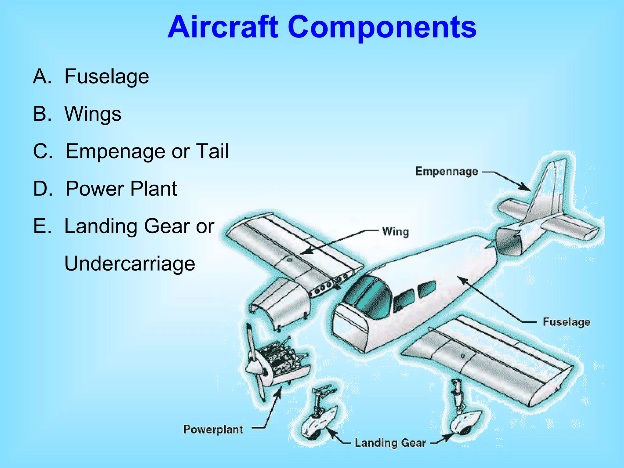
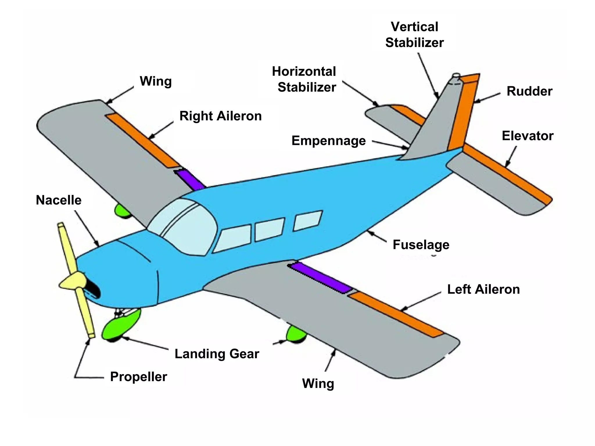
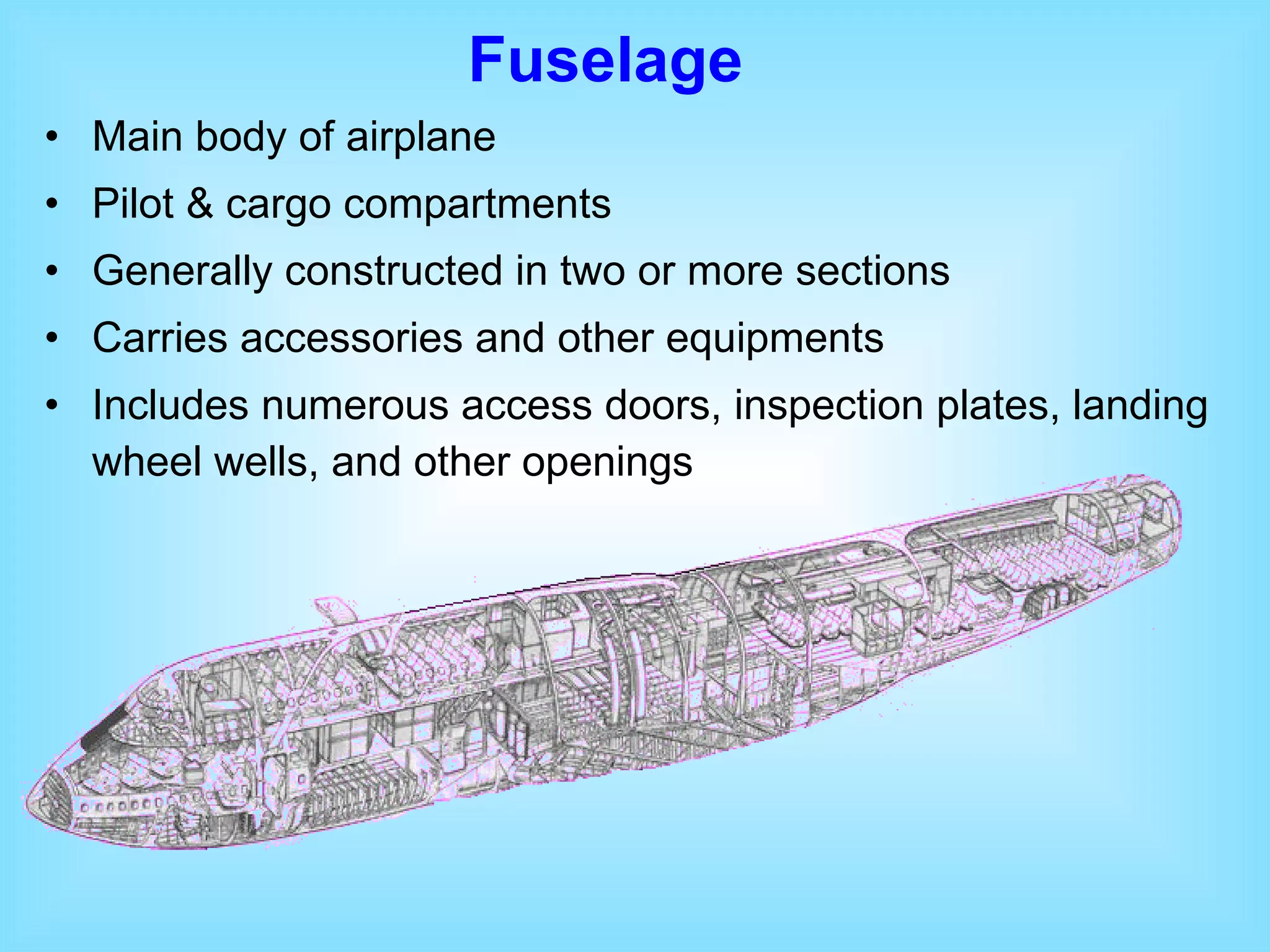
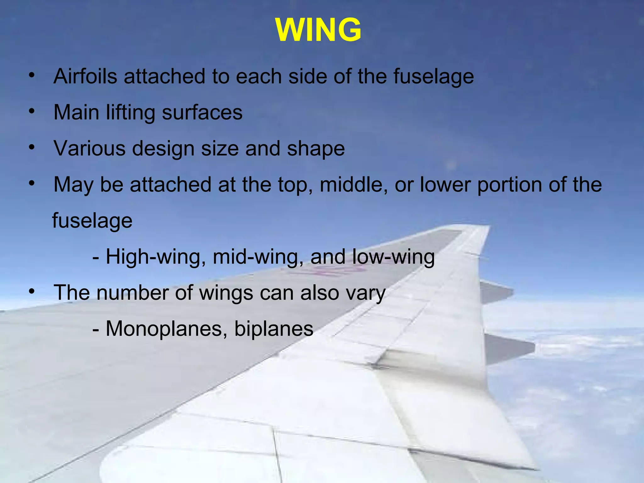
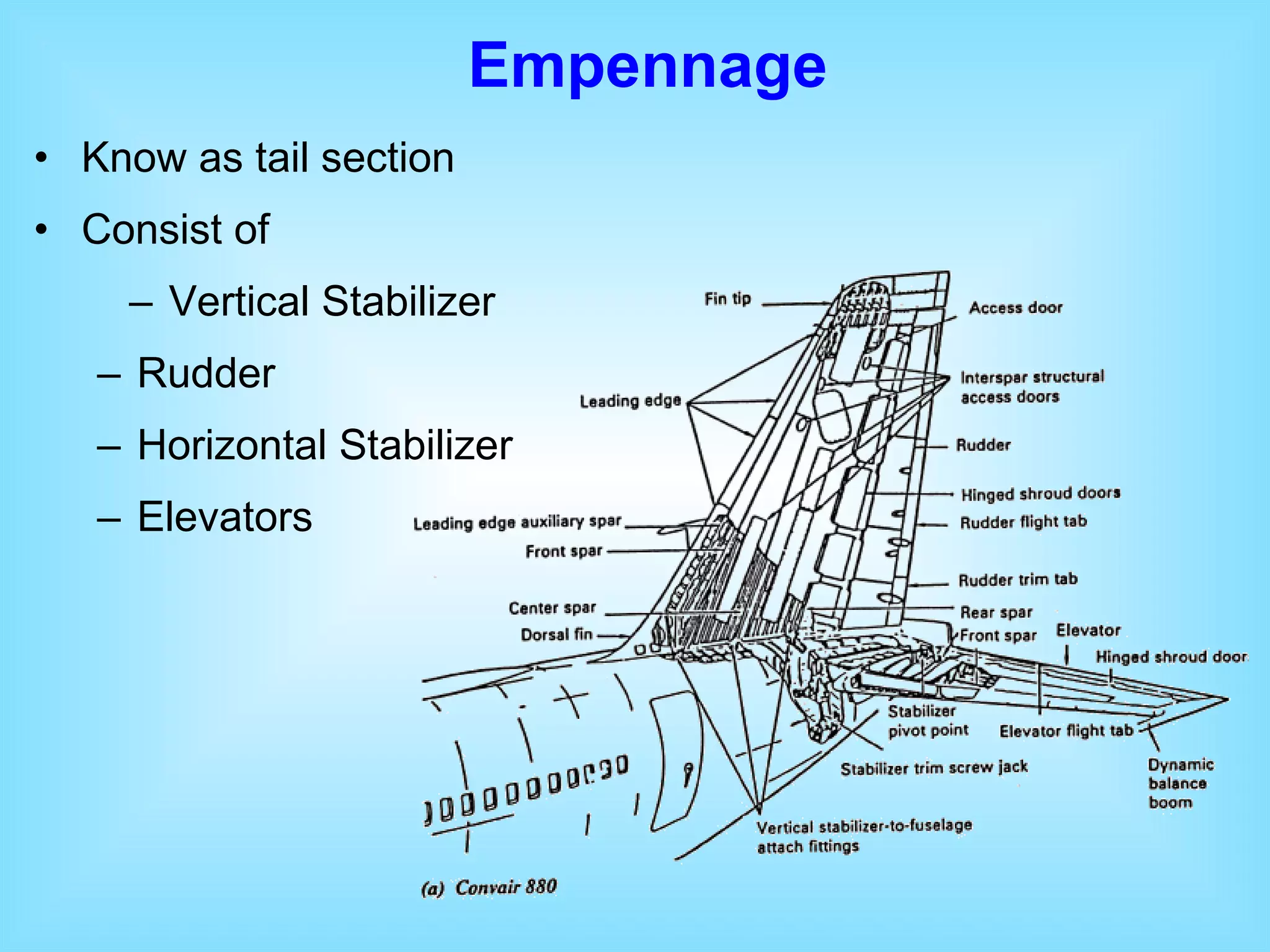
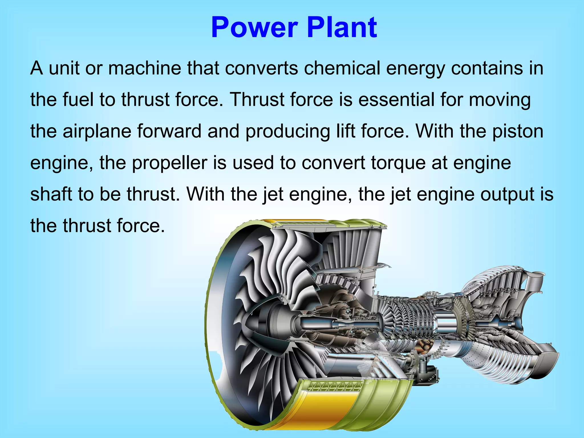
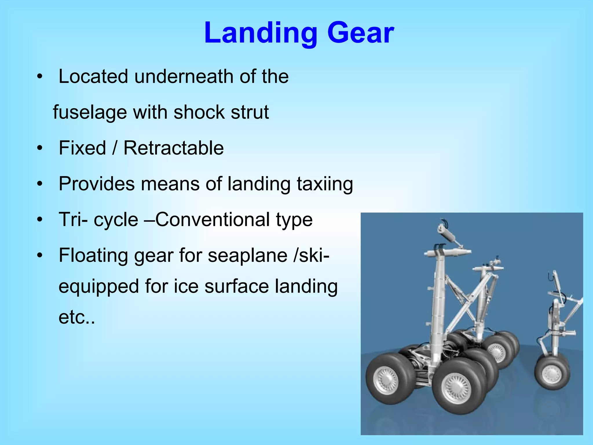
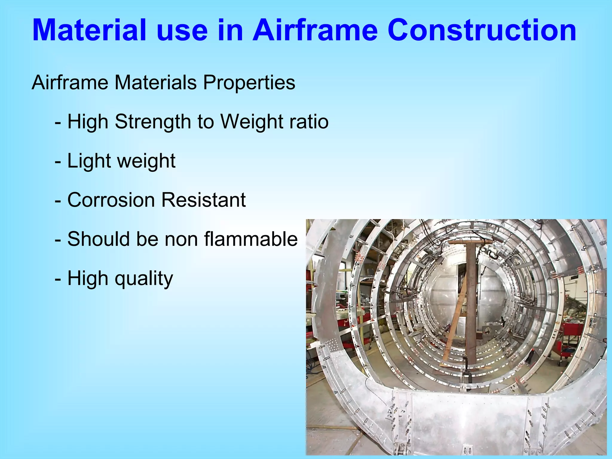
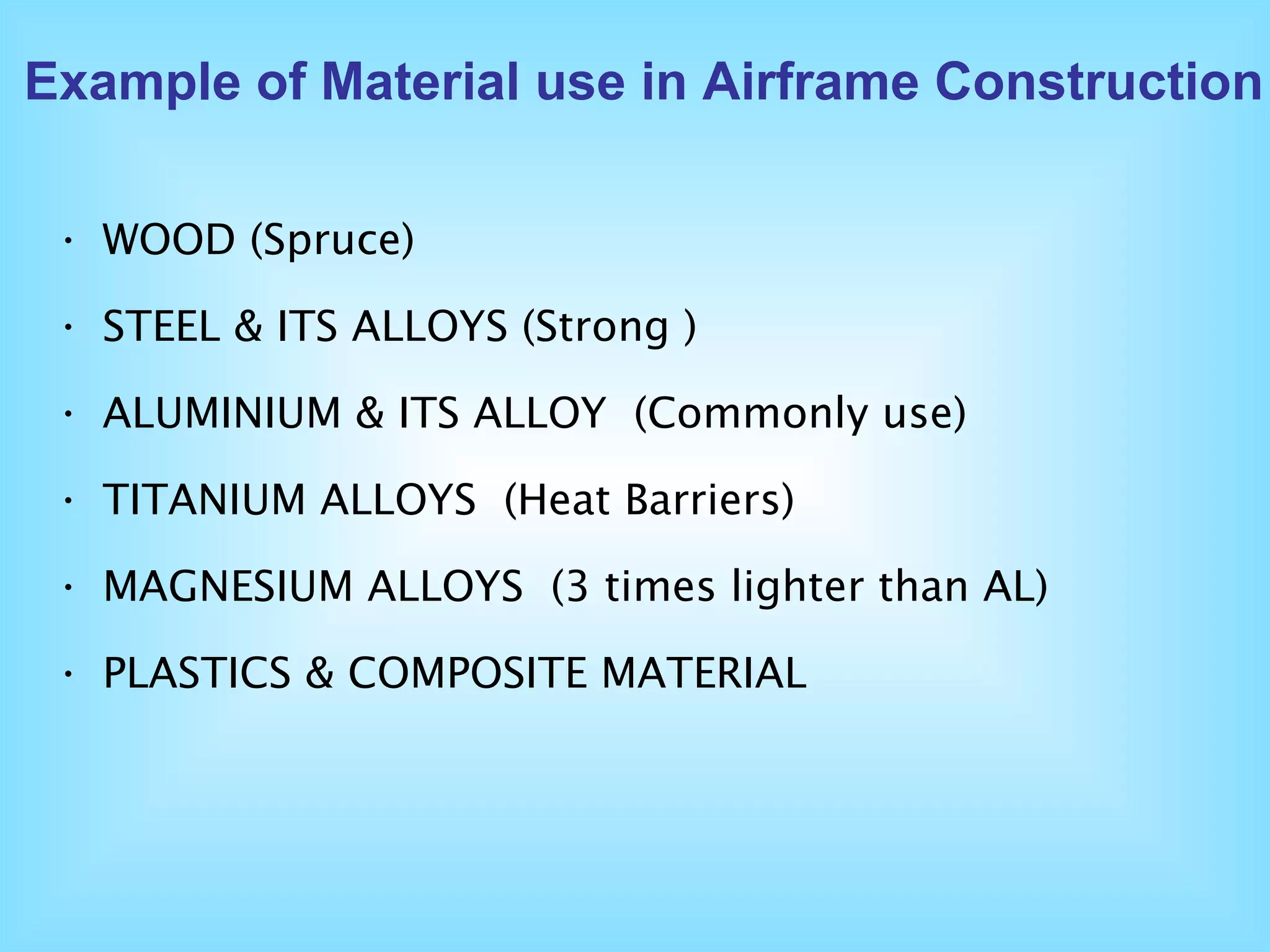
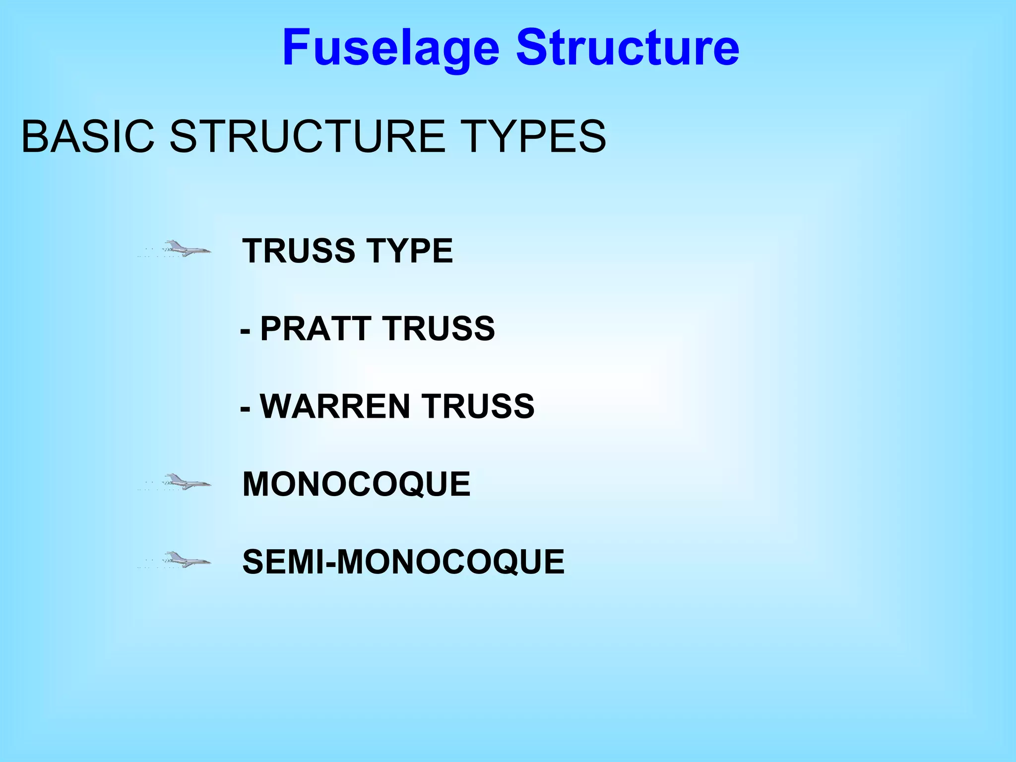
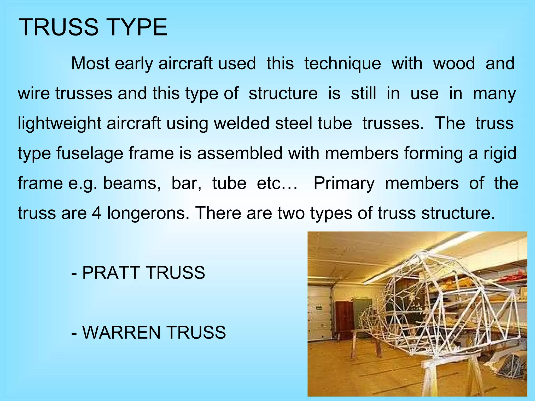
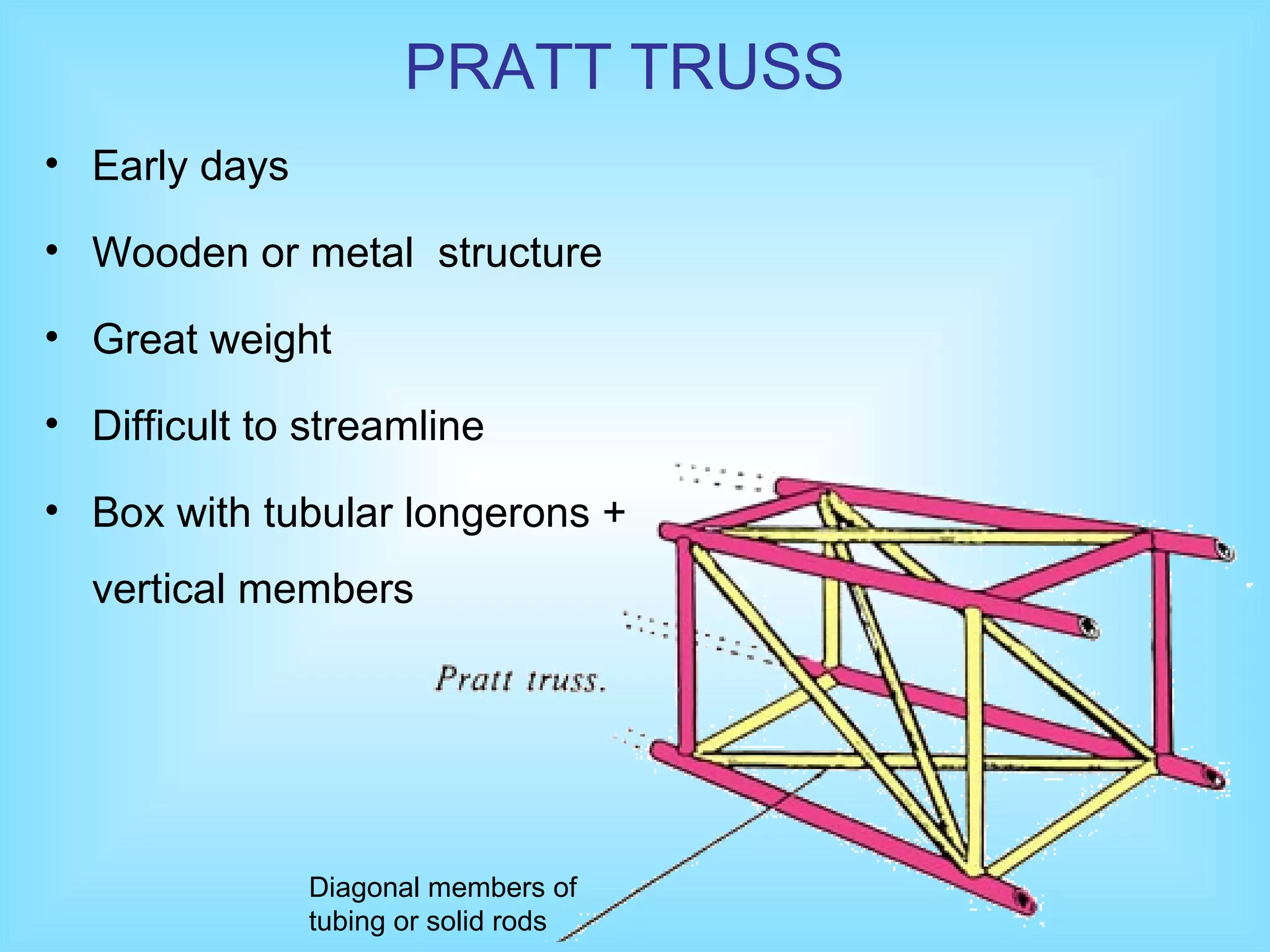
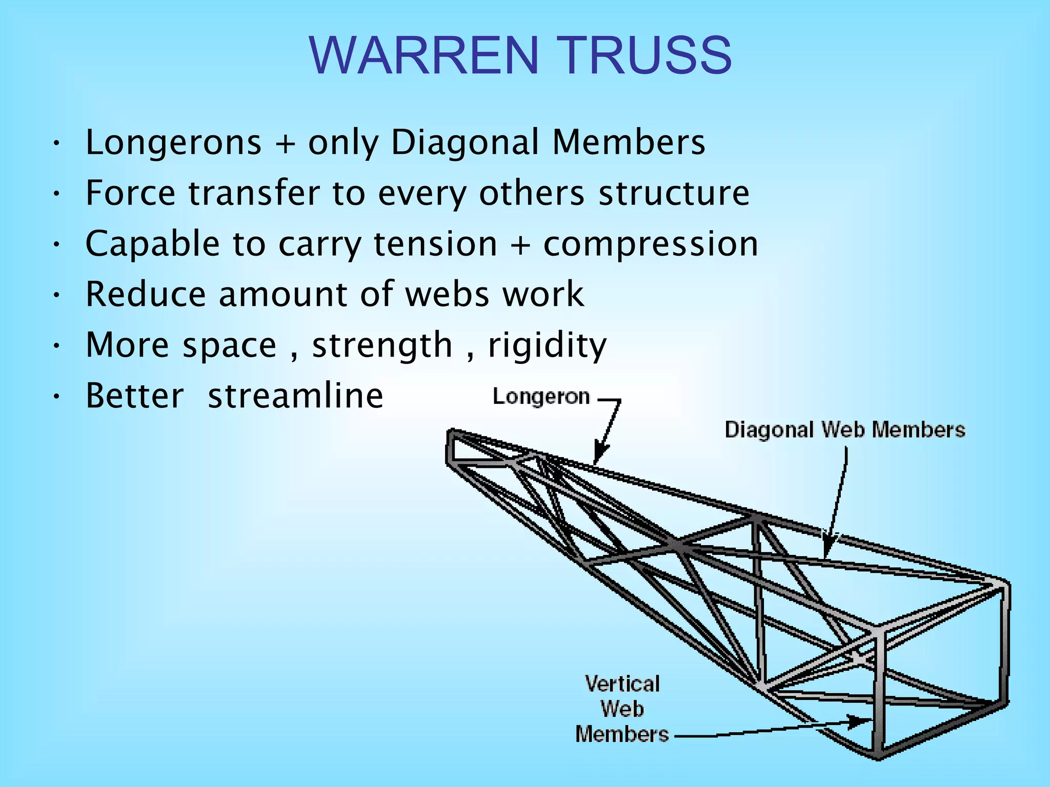
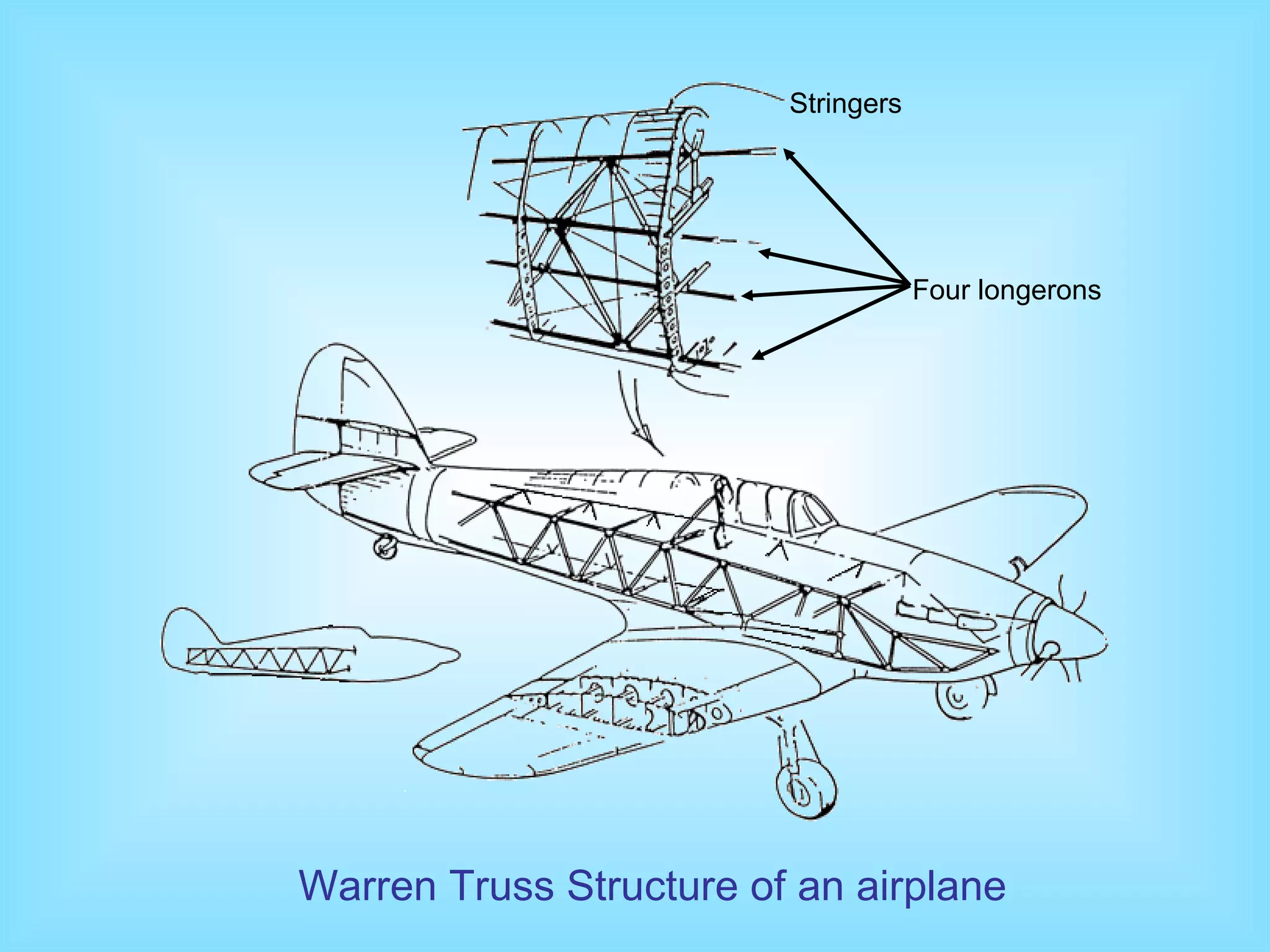
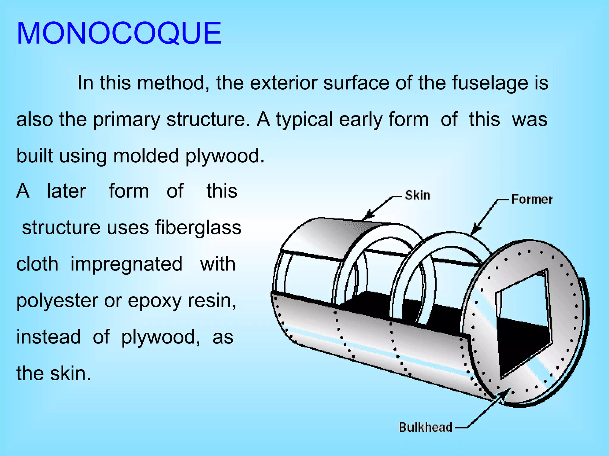
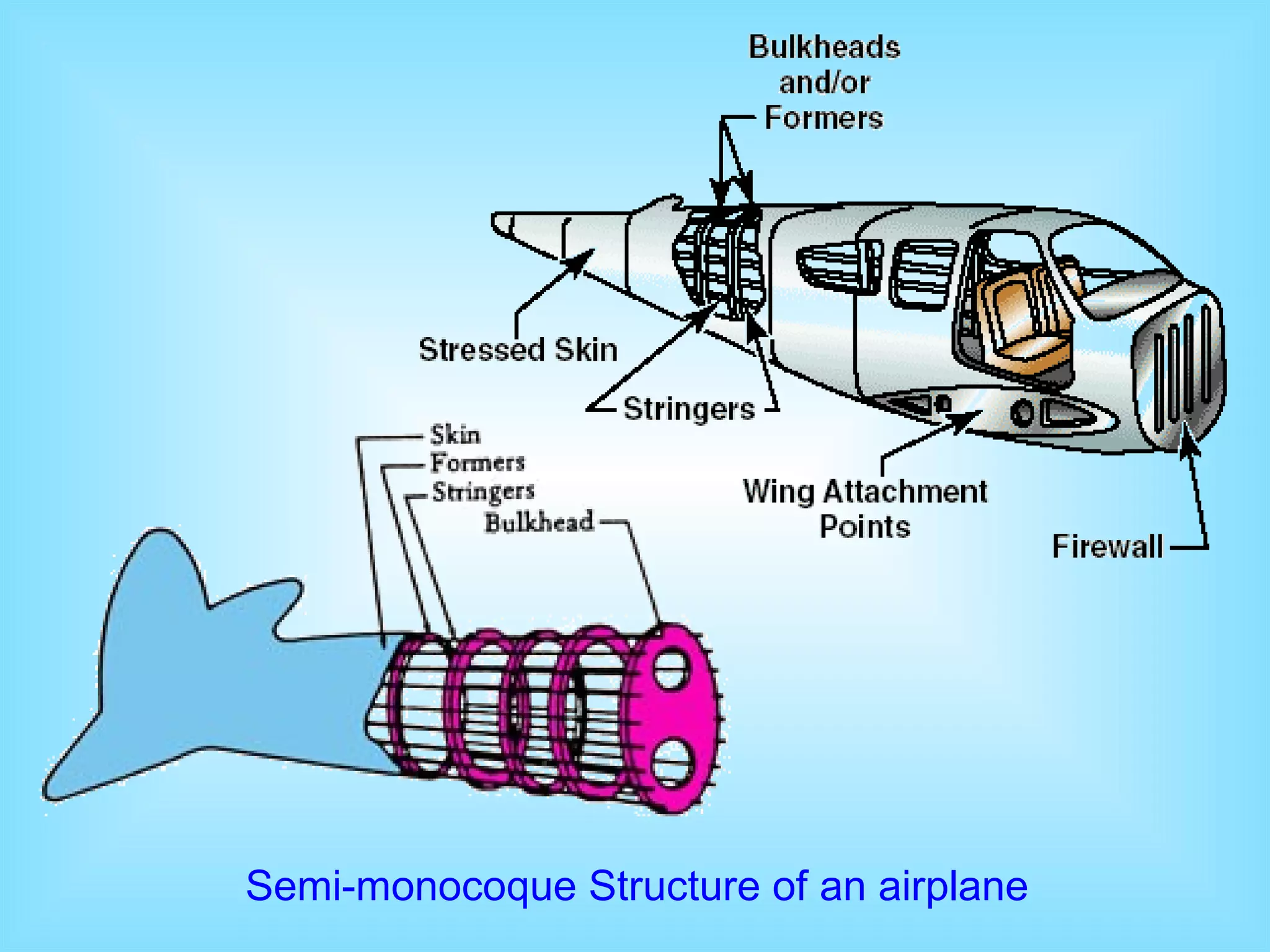
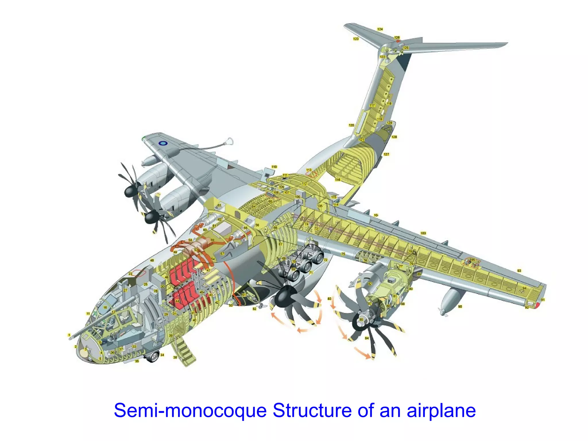
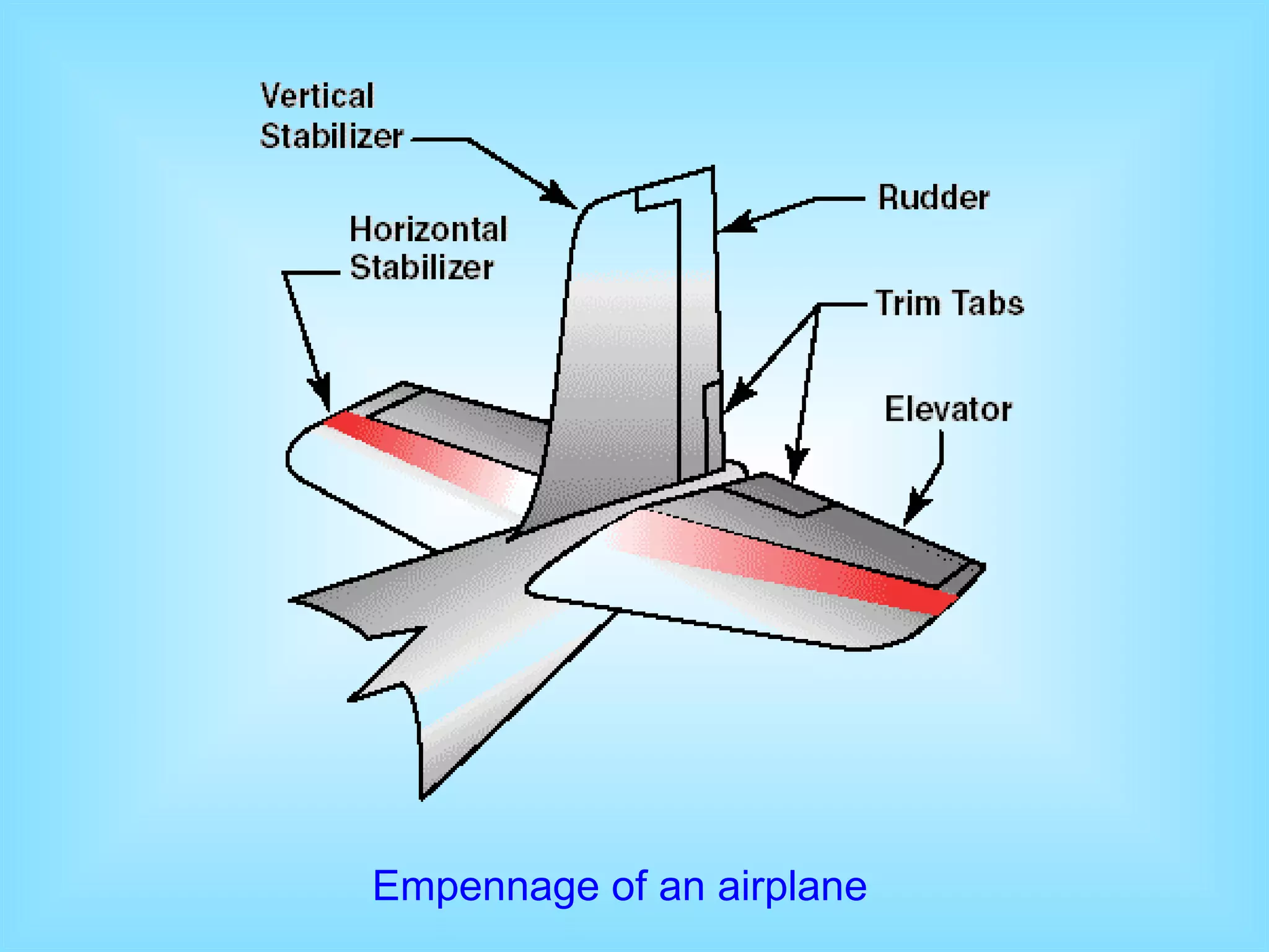
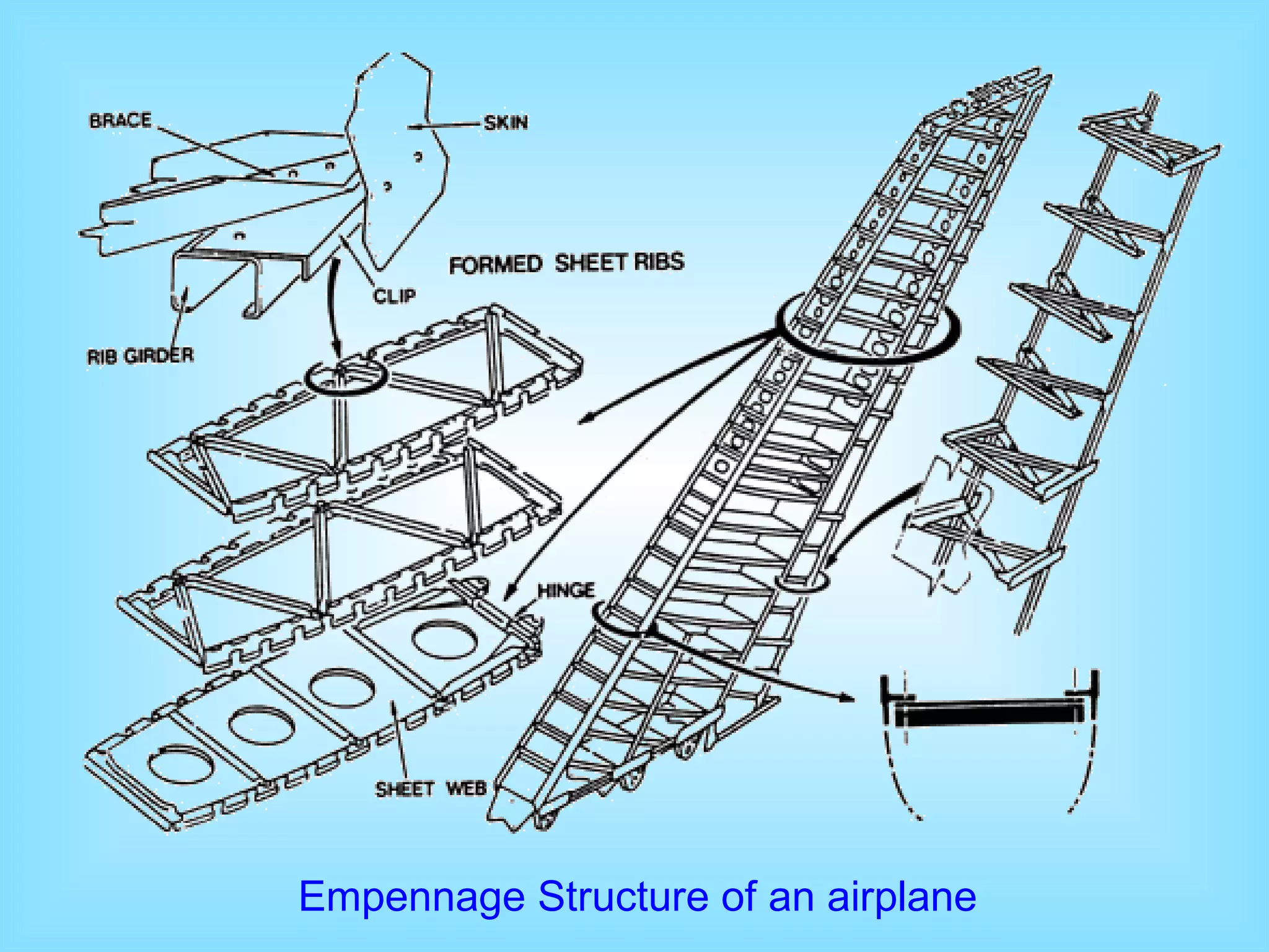
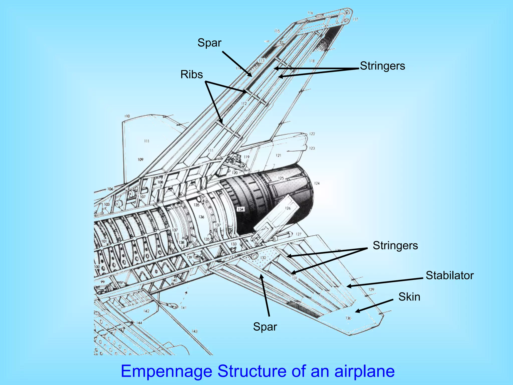
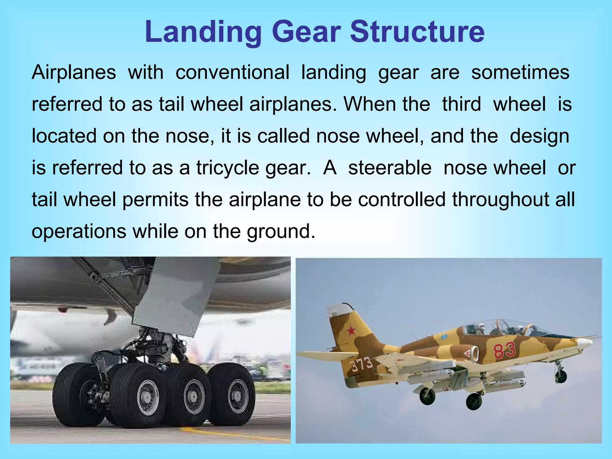
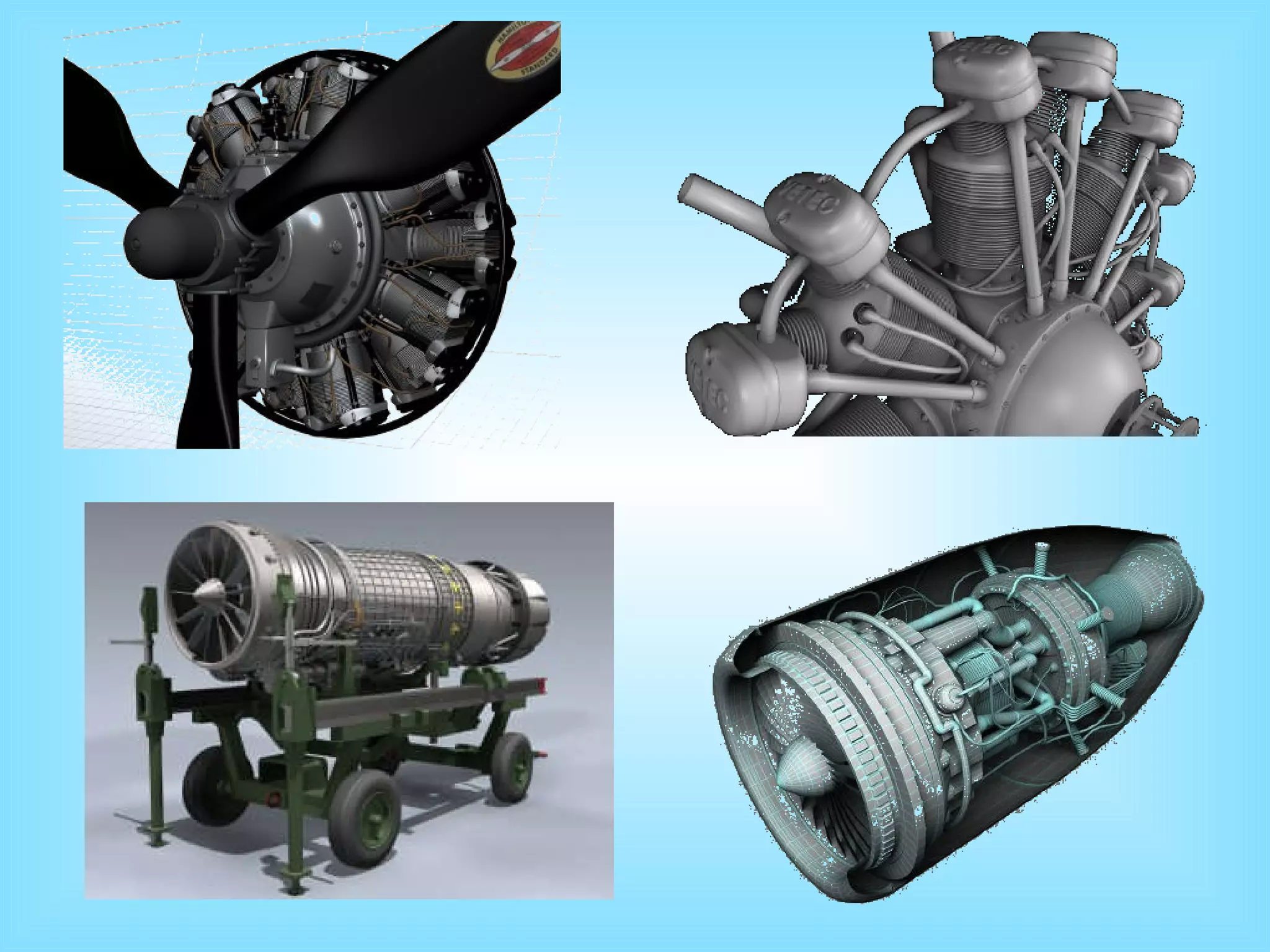
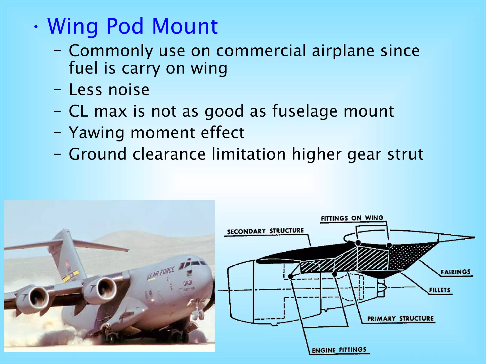
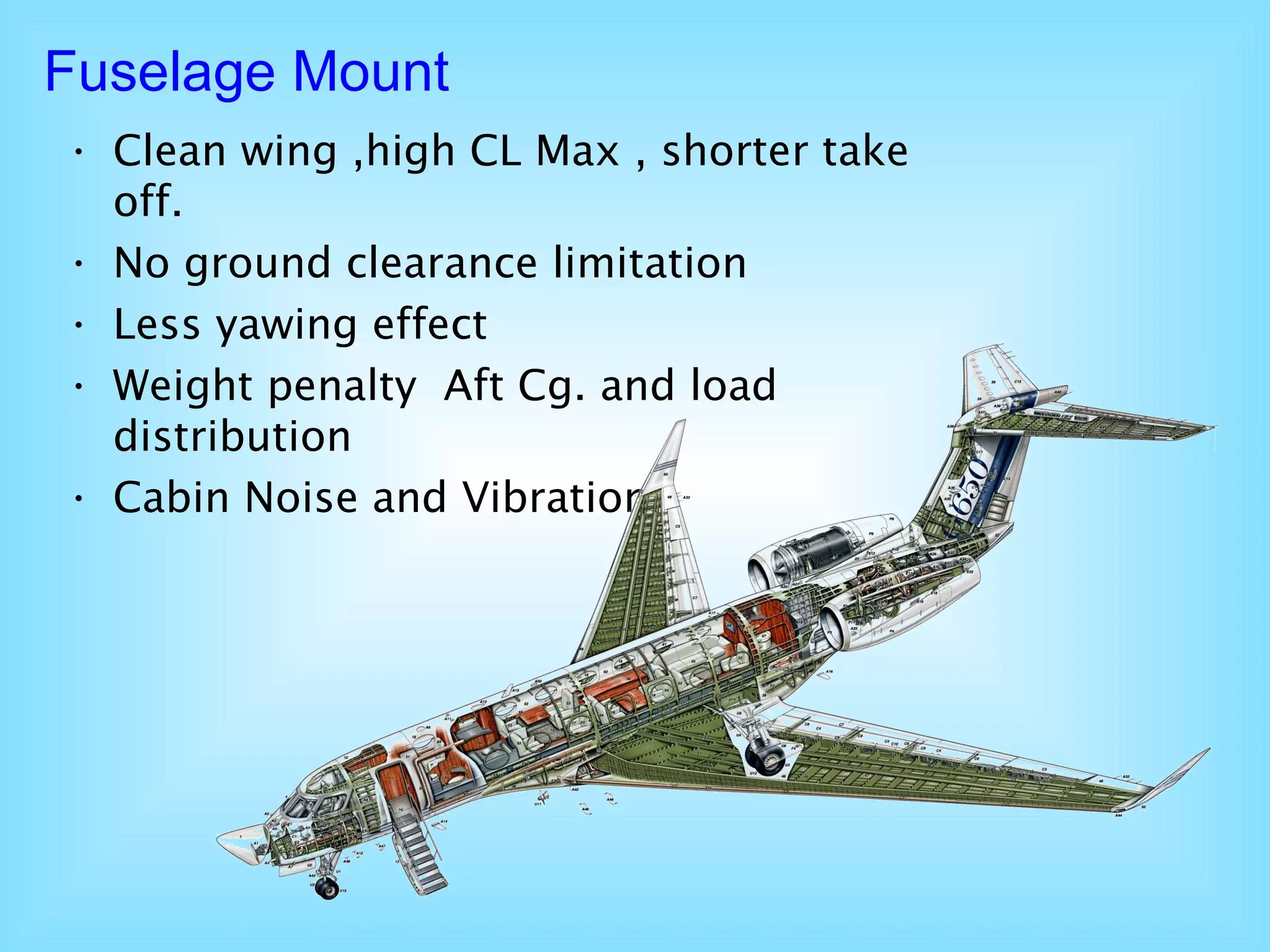
Basic Aircraft Structure
Outline of Presentation Aircraft Components Material use in Airframe Construction Example of Material use in Airframe Construction Fuselage  Structure - Truss Type - Pratt Truss - Warren Truss - Monocoque - Semi-Monocoque Basic Structure Member   Terms Wing Structure Empennage Structure Power Plant - Wing Pod Mount -Fuselage Mount Landing Gear Structure
A.   Fuselage B.   Wings C.   Empenage  or Tail D.   Power Plant E.   Landing Gear  or  Undercarriage Aircraft Components
Propeller Landing Gear Wing Left Aileron Fuselage Empennage Nacelle Right Aileron Wing Horizontal Stabilizer Vertical Stabilizer Rudder Elevator
Main  b ody of airplane Pilot &  c argo  c ompartments Generally constructed in two or more sections Carries  accessories and other equipment s Includes  numerous access doors, inspection plates, landing wheel wells, and other openings Fuselage
Airfoils attached to each side of the fuselage Main lifting surfaces Various design size and shape May be attached at the top, middle, or lower portion of the  fuselage - High-wing, mid-wing, and low-wing The number of wings can also vary - Monoplanes, biplanes WING
Know as tail section Consist of  Vertical Stabi li zer Rudder Horizontal  S tabilizer Elevators Empe n nage
Power Plant A unit or machine that converts chemical energy contains in the fuel to thrust force. Thrust force is essential for moving the airplane forward and producing lift force. With the piston engine, the propeller is used to convert torque at engine shaft to be thrust. With the jet engine, the jet engine output is the thrust force.
Located underneath of the fuselage with shock strut  Fixed / Retractable Provides means of landing taxiing Tri- cycle –Conventional type Floating gear for seaplane /ski- equipped for ice surface landing etc.. Landing Gear
Material use in Airframe Construction   Airframe Materials Properties - High Strength to Weight ratio - Light weight - Corrosion Resistant  - Should be non flammable - High quality
WOOD  (Spruce) STEEL & ITS ALLOYS  (Strong ) ALUMINIUM & ITS ALLOY   (Commonly use) TITANIUM ALLOYS  (Heat Barriers) MAGNESIUM ALLOYS   (3 times lighter than AL) PLASTICS & COMPOSITE MATERIAL Example of Material use in Airframe Construction
Fuselage  Structure BASIC STRUCTURE TYPE S TRUSS TYPE - PRATT TRUSS - WARREN TRUSS MONOCOQUE SEMI-MONOCOQUE
TRUSS TYPE Most early aircraft used  this  technique  with  wood  and wire trusses and this type of  structure  is  still  in  use  in  many lightweight aircraft using welded steel tube  trusses.  The  truss type fuselage frame is assembled with members forming a rigid frame e.g. beams,  bar,  tube  etc…  Primary  members  of  the truss are 4 longerons. There are two types of truss structure. - PRATT TRUSS - WARREN TRUSS
PRATT TRUSS Early day s Wooden or metal  structure  Great weight Difficult to streamline Box with tubular longerons + vertical members Diagonal members of tubing or solid rods
L ongerons  +  only  D iagonal  M embers Force transfer to every others structure Capable to carry tension + compression Reduce amount of webs work More space , strength , rigidity Better  streamline WARREN  TRUSS
Warren  T russ Structure of an airplane Stringers Four longerons
MONOCOQUE  In this method, the exterior surface of the fuselage is also the primary structure. A typical early form  of  this  was built using molded plywood.  A  later  form  of  this  structure uses fiberglass cloth  impregnated  with  polyester or epoxy resin, instead  of  plywood,  as the skin.
SEMI-MONOCOQUE This is the preferred method  of  constructing  an  all-aluminum fuselage. First, a series of frames in the shape of the fuselage cross sections are held in  position  on  a  rigid fixture, or  jig . These frames are then joined with  lightweight longitudinal elements  called  stringers.  These  are  in  turn covered with a skin of sheet aluminum, attached by riveting or by bonding with special  adhesives.  Most  modern  large aircraft are built using this technique, but use several  large sections constructed in this fashion which  are  then  joined with fasteners to form the complete fuselage.
Semi-monocoque Structure of an airplane
Basic Structure Member   Terms Vertical Members Formers Frame  Ring  Bulkhead Longitudinal Members Longerons Stringers
Wing Structure Many high-wing airplanes have external braces, or wing  struts, which transmit the flight and landing loads through the struts  to the main fuselage structure. Since the  wing  struts  are  usually attached approximately halfway out on  the  wing,  this  type  of wing structure is called  semi-cantilever .  A  few  high-wing  and most low-wing airplanes have a  full cantilever  wing designed to carry the loads without external struts.  The  principal  structural parts of  the  wing  are  spars,  ribs,  and  stringers.  These  are reinforced  by  trusses,  I-beams,  tubing,  or  other  devices, including the skin.  The  wing  ribs  determine  the  shape  and thickness of the wing (airfoil).
In most modern airplanes, the fuel tanks either are an integral part of the  wing  structure,  or  consist  of  flexible  containers mounted inside of the wing. Attached  to  the  rear,  or  trailing, edges of the wings are two types of control  surfaces  referred to  as  ailerons   and  flaps .  Ailerons  extend  from  about  the midpoint of each wing outward  toward  the  tip  and  move  in opposite directions to create aerodynamic  forces  that  cause the airplane to roll. Flaps extend outward from the fuselage to near the midpoint of each wing. The flaps  are  normally  flush with the wing´s surface during cruising flight. When extended, the  flaps  move  simultaneously  downward  to  increase  the lifting force of the wing for takeoffs and landings.  Wing  Structure
Wing Structure of an airplane
Empennage  Structure The  correct  name  for  the  tail  section  of  an  airplane  is empennage. The empennage includes the entire tail group, consisting of fixed surfaces such  as  the  vertical  stabilizer and the horizontal stabilizer. The movable surfaces include the rudder,  the  elevator,  and  one  or  more  trim  tabs.  A second type  of  empennage  design  does  not  require  an elevator.  Instead,  it  incorporates  a  one-piece  horizontal stabilizer that pivots from a central hinge point. This type of design is called a  stabilator , and is moved using the control stick, just as you would the elevator.
The rudder is attached to the back of the vertical  stabilizer.  During flight, it is used to move the airplane´s nose left  and right. The rudder is used in  combination  with  the  ailerons for turns during flight. The elevator, which is attached to the back of the horizontal stabilizer, is used to  move  the  nose of the airplane up and down during flight.  Trim tabs are small, movable portions of the trailing edge of the control surface.  These  movable  trim  tabs,  which  are controlled from the cockpit, reduce control  pressures.  Trim tabs may be installed on the ailerons, the rudder, and/or the elevator.  Empennage  Structure
Empennage of an airplane
Empennage Structure of an airplane
Empennage Structure of an airplane Spar Ribs Stringers Skin Spar Stringers Stabilator
The landing gear is the principle support of the  airplane  when parked, taxiing, taking off, or when landing. The most common type of landing gear consists of wheels, but airplanes can also be equipped with floats for water operations, or skis for landing on snow. The landing gear  consists  of  three  wheels  —  two main wheels and a third wheel positioned either at the front or rear of the airplane. Landing  gear  employing  a  rearmounted wheel is called conventional landing gear.  Landing Gear Structure
Airplanes  with  conventional  landing  gear  are  sometimes referred to as tail wheel airplanes. When the  third  wheel  is located on the nose, it is called nose wheel, and the  design is referred to as a tricycle gear.  A  steerable  nose wheel  or tail wheel permits the airplane to be controlled throughout all operations while on the ground. Landing Gear Structure
The power plant  usually  includes  both  the  engine  and  the propeller. The primary function of the engine is to provide  the power to turn the propeller. It also generates electrical power, provides a vacuum source for some flight instruments, and  in most single-engine airplanes, provides  a  source  of  heat  for the pilot and passengers. The engine is covered by a cowling, or in the case of  some  airplanes,  surrounded  by  a  nacelle.  The purpose of the cowling or nacelle is to streamline the flow of  air  around  the  engine  and  to  help  cool  the  engine  by ducting air around the cylinders.  The  propeller,  mounted  on the front of the  engine,  translates  the  rotating  force  of  the engine into a forward acting force called thrust that helps move the airplane through the air.  Power Plant
 
Wing Pod Mount   Commonly use on commercial airplane since fuel is carry on wing Less noise CL max is not as good as fuselage mount Yawing moment effect Ground clearance limitation higher gear strut
Clean wing ,high CL Max , shorter take off. No ground   clearance limitation Less yawing effect Weight penalty  Aft Cg. and load distribution  Cabin Noise and Vibration Fuselage Mount
Any Question? Thank You

Basic aircraft structure

  • 1.
  • 2.
    Outline of PresentationAircraft Components Material use in Airframe Construction Example of Material use in Airframe Construction Fuselage Structure - Truss Type - Pratt Truss - Warren Truss - Monocoque - Semi-Monocoque Basic Structure Member Terms Wing Structure Empennage Structure Power Plant - Wing Pod Mount -Fuselage Mount Landing Gear Structure
  • 3.
    A. Fuselage B. Wings C. Empenage or Tail D. Power Plant E. Landing Gear or Undercarriage Aircraft Components
  • 4.
    Propeller Landing GearWing Left Aileron Fuselage Empennage Nacelle Right Aileron Wing Horizontal Stabilizer Vertical Stabilizer Rudder Elevator
  • 5.
    Main body of airplane Pilot & c argo c ompartments Generally constructed in two or more sections Carries accessories and other equipment s Includes numerous access doors, inspection plates, landing wheel wells, and other openings Fuselage
  • 6.
    Airfoils attached toeach side of the fuselage Main lifting surfaces Various design size and shape May be attached at the top, middle, or lower portion of the fuselage - High-wing, mid-wing, and low-wing The number of wings can also vary - Monoplanes, biplanes WING
  • 7.
    Know as tailsection Consist of Vertical Stabi li zer Rudder Horizontal S tabilizer Elevators Empe n nage
  • 8.
    Power Plant Aunit or machine that converts chemical energy contains in the fuel to thrust force. Thrust force is essential for moving the airplane forward and producing lift force. With the piston engine, the propeller is used to convert torque at engine shaft to be thrust. With the jet engine, the jet engine output is the thrust force.
  • 9.
    Located underneath ofthe fuselage with shock strut Fixed / Retractable Provides means of landing taxiing Tri- cycle –Conventional type Floating gear for seaplane /ski- equipped for ice surface landing etc.. Landing Gear
  • 10.
    Material use inAirframe Construction Airframe Materials Properties - High Strength to Weight ratio - Light weight - Corrosion Resistant - Should be non flammable - High quality
  • 11.
    WOOD (Spruce)STEEL & ITS ALLOYS (Strong ) ALUMINIUM & ITS ALLOY (Commonly use) TITANIUM ALLOYS (Heat Barriers) MAGNESIUM ALLOYS (3 times lighter than AL) PLASTICS & COMPOSITE MATERIAL Example of Material use in Airframe Construction
  • 12.
    Fuselage StructureBASIC STRUCTURE TYPE S TRUSS TYPE - PRATT TRUSS - WARREN TRUSS MONOCOQUE SEMI-MONOCOQUE
  • 13.
    TRUSS TYPE Mostearly aircraft used this technique with wood and wire trusses and this type of structure is still in use in many lightweight aircraft using welded steel tube trusses. The truss type fuselage frame is assembled with members forming a rigid frame e.g. beams, bar, tube etc… Primary members of the truss are 4 longerons. There are two types of truss structure. - PRATT TRUSS - WARREN TRUSS
  • 14.
    PRATT TRUSS Earlyday s Wooden or metal structure Great weight Difficult to streamline Box with tubular longerons + vertical members Diagonal members of tubing or solid rods
  • 15.
    L ongerons + only D iagonal M embers Force transfer to every others structure Capable to carry tension + compression Reduce amount of webs work More space , strength , rigidity Better streamline WARREN TRUSS
  • 16.
    Warren Truss Structure of an airplane Stringers Four longerons
  • 17.
    MONOCOQUE Inthis method, the exterior surface of the fuselage is also the primary structure. A typical early form of this was built using molded plywood. A later form of this structure uses fiberglass cloth impregnated with polyester or epoxy resin, instead of plywood, as the skin.
  • 18.
    SEMI-MONOCOQUE This isthe preferred method of constructing an all-aluminum fuselage. First, a series of frames in the shape of the fuselage cross sections are held in position on a rigid fixture, or jig . These frames are then joined with lightweight longitudinal elements called stringers. These are in turn covered with a skin of sheet aluminum, attached by riveting or by bonding with special adhesives. Most modern large aircraft are built using this technique, but use several large sections constructed in this fashion which are then joined with fasteners to form the complete fuselage.
  • 19.
  • 20.
  • 21.
    Basic Structure Member Terms Vertical Members Formers Frame Ring Bulkhead Longitudinal Members Longerons Stringers
  • 22.
    Wing Structure Manyhigh-wing airplanes have external braces, or wing struts, which transmit the flight and landing loads through the struts to the main fuselage structure. Since the wing struts are usually attached approximately halfway out on the wing, this type of wing structure is called semi-cantilever . A few high-wing and most low-wing airplanes have a full cantilever wing designed to carry the loads without external struts. The principal structural parts of the wing are spars, ribs, and stringers. These are reinforced by trusses, I-beams, tubing, or other devices, including the skin. The wing ribs determine the shape and thickness of the wing (airfoil).
  • 23.
    In most modernairplanes, the fuel tanks either are an integral part of the wing structure, or consist of flexible containers mounted inside of the wing. Attached to the rear, or trailing, edges of the wings are two types of control surfaces referred to as ailerons and flaps . Ailerons extend from about the midpoint of each wing outward toward the tip and move in opposite directions to create aerodynamic forces that cause the airplane to roll. Flaps extend outward from the fuselage to near the midpoint of each wing. The flaps are normally flush with the wing´s surface during cruising flight. When extended, the flaps move simultaneously downward to increase the lifting force of the wing for takeoffs and landings. Wing Structure
  • 24.
    Wing Structure ofan airplane
  • 25.
    Empennage StructureThe correct name for the tail section of an airplane is empennage. The empennage includes the entire tail group, consisting of fixed surfaces such as the vertical stabilizer and the horizontal stabilizer. The movable surfaces include the rudder, the elevator, and one or more trim tabs. A second type of empennage design does not require an elevator. Instead, it incorporates a one-piece horizontal stabilizer that pivots from a central hinge point. This type of design is called a stabilator , and is moved using the control stick, just as you would the elevator.
  • 26.
    The rudder isattached to the back of the vertical stabilizer. During flight, it is used to move the airplane´s nose left and right. The rudder is used in combination with the ailerons for turns during flight. The elevator, which is attached to the back of the horizontal stabilizer, is used to move the nose of the airplane up and down during flight. Trim tabs are small, movable portions of the trailing edge of the control surface. These movable trim tabs, which are controlled from the cockpit, reduce control pressures. Trim tabs may be installed on the ailerons, the rudder, and/or the elevator. Empennage Structure
  • 27.
  • 28.
  • 29.
    Empennage Structure ofan airplane Spar Ribs Stringers Skin Spar Stringers Stabilator
  • 30.
    The landing gearis the principle support of the airplane when parked, taxiing, taking off, or when landing. The most common type of landing gear consists of wheels, but airplanes can also be equipped with floats for water operations, or skis for landing on snow. The landing gear consists of three wheels — two main wheels and a third wheel positioned either at the front or rear of the airplane. Landing gear employing a rearmounted wheel is called conventional landing gear. Landing Gear Structure
  • 31.
    Airplanes with conventional landing gear are sometimes referred to as tail wheel airplanes. When the third wheel is located on the nose, it is called nose wheel, and the design is referred to as a tricycle gear. A steerable nose wheel or tail wheel permits the airplane to be controlled throughout all operations while on the ground. Landing Gear Structure
  • 32.
    The power plant usually includes both the engine and the propeller. The primary function of the engine is to provide the power to turn the propeller. It also generates electrical power, provides a vacuum source for some flight instruments, and in most single-engine airplanes, provides a source of heat for the pilot and passengers. The engine is covered by a cowling, or in the case of some airplanes, surrounded by a nacelle. The purpose of the cowling or nacelle is to streamline the flow of air around the engine and to help cool the engine by ducting air around the cylinders. The propeller, mounted on the front of the engine, translates the rotating force of the engine into a forward acting force called thrust that helps move the airplane through the air. Power Plant
  • 33.
  • 34.
    Wing Pod Mount Commonly use on commercial airplane since fuel is carry on wing Less noise CL max is not as good as fuselage mount Yawing moment effect Ground clearance limitation higher gear strut
  • 35.
    Clean wing ,highCL Max , shorter take off. No ground clearance limitation Less yawing effect Weight penalty Aft Cg. and load distribution Cabin Noise and Vibration Fuselage Mount
  • 36.