SlideShare a Scribd company logo
Aerodynamics of Wind Turbines
Part -3
Airfoils and general aerodynamic concepts
Wind turbine blades use airfoil sections to develop
mechanical power.
The width and length of the blades are a function
of the desired aerodynamic performance and the
maximum desired rotor power (as well as strength
considerations).
Before examining the details of wind turbine power
production, some airfoil aerodynamic principles
are reviewed here.
Basic airfoil terminology
Camber = distance between mean camber line (mid-point of airfoil) and
the chord line (straight line from leading edge to trailing edge)
Thickness = distance between upper and lower surfaces (measured
perpendicular to chord line)
Span = length of airfoil normal to the cross-section
Camber
Thickness
Examples of standard airfoil shapes
National Advisory Committee for Aeronautics
NACA 0012 = 12% thick symmetric airfoil
NACA 63(2)-215 = 15% thick airfoil with slight camber
LS(1)-0417 = 17% thick airfoil with larger camber
Lift, drag and non-dimensional parameters
Airflow over an airfoil produces a distribution of
forces over the airfoil surface.
The flow velocity over airfoils increases over the
convex surface resulting in lower average
pressure on the 'suction' side of the airfoil
compared with the concave or 'pressure' side of
the airfoil.
Meanwhile, viscous friction between the air and
the airfoil surface slows the airflow to some
extent next to the surface.
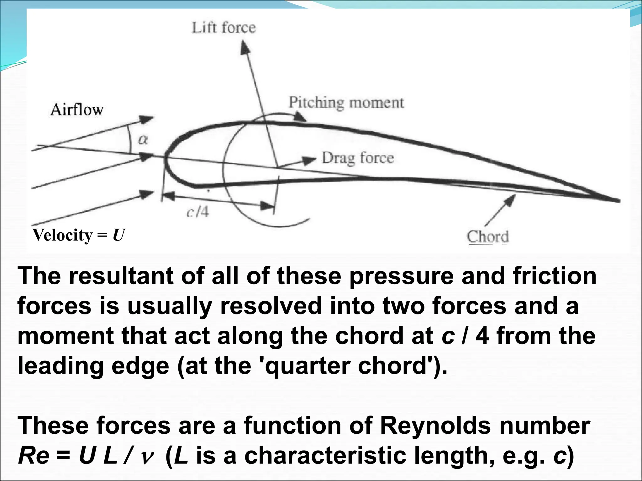
Lift force - defined to be perpendicular to
direction of the oncoming airflow. The lift
force is a consequence of the unequal pressure
on the upper and lower airfoil surfaces
Drag force - defined to be parallel to the direction
of oncoming airflow. The drag force is due both
to viscous friction forces at the surface of the
airfoil and to unequal pressure on the airfoil
surfaces facing toward and away from the
oncoming flow
Pitching moment - defined to be about an axis
perpendicular to the airfoil cross-section
The resultant of all of these pressure and friction
forces is usually resolved into two forces and a
moment that act along the chord at c / 4 from the
leading edge (at the 'quarter chord').
These forces are a function of Reynolds number
Re = U L /  (L is a characteristic length, e.g. c)
Velocity = U
The 2-D airfoil section lift, drag and pitching
moment coefficients are normally defined as:
A = projected airfoil area = chord x span = c l
Other dimensionless parameters that are
important for analysis and design of wind turbines
include the power and thrust coefficients and tip
speed ratio, mentioned earlier and also the
pressure coefficient:
and blade surface roughness ratio:
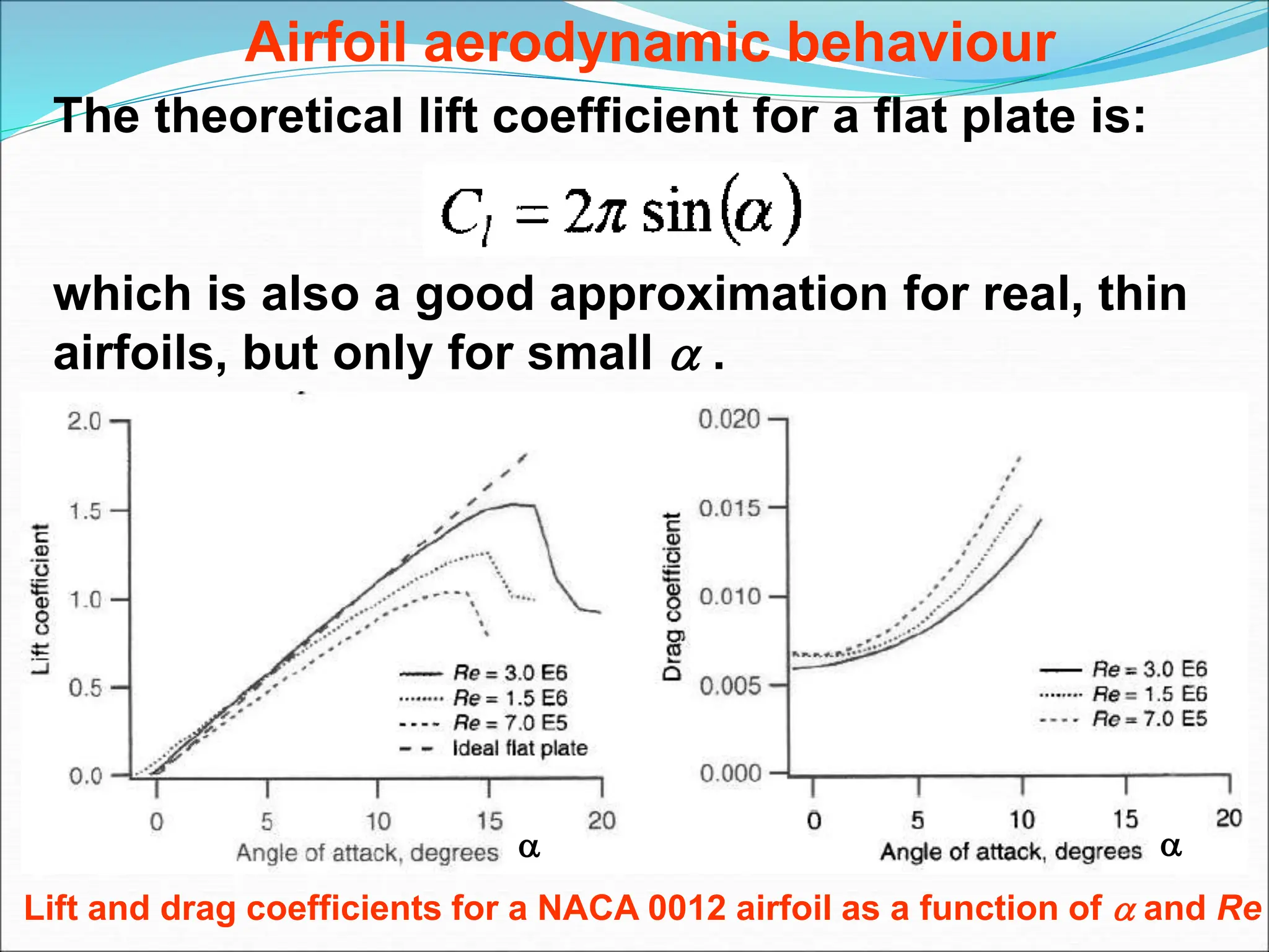
Airfoil aerodynamic behaviour
The theoretical lift coefficient for a flat plate is:
which is also a good approximation for real, thin
airfoils, but only for small  .
Lift and drag coefficients for a NACA 0012 airfoil as a function of  and Re
 
Airfoils for HAWT are often designed to be used at
low angles of attack, where lift coefficients are
fairly high and drag coefficients are fairly low.
The lift coefficient of this symmetric airfoil is about
zero at an angle of attack of zero and increases to
over 1.0 before decreasing at higher angles of
attack.
The drag coefficient is usually much lower than the
lift coefficient at low angles of attack. It increases
at higher angles of attack.
Note the significant differences in airfoil behaviour
at different Re. Rotor designers must make sure
that appropriate Re data are available for analysis.
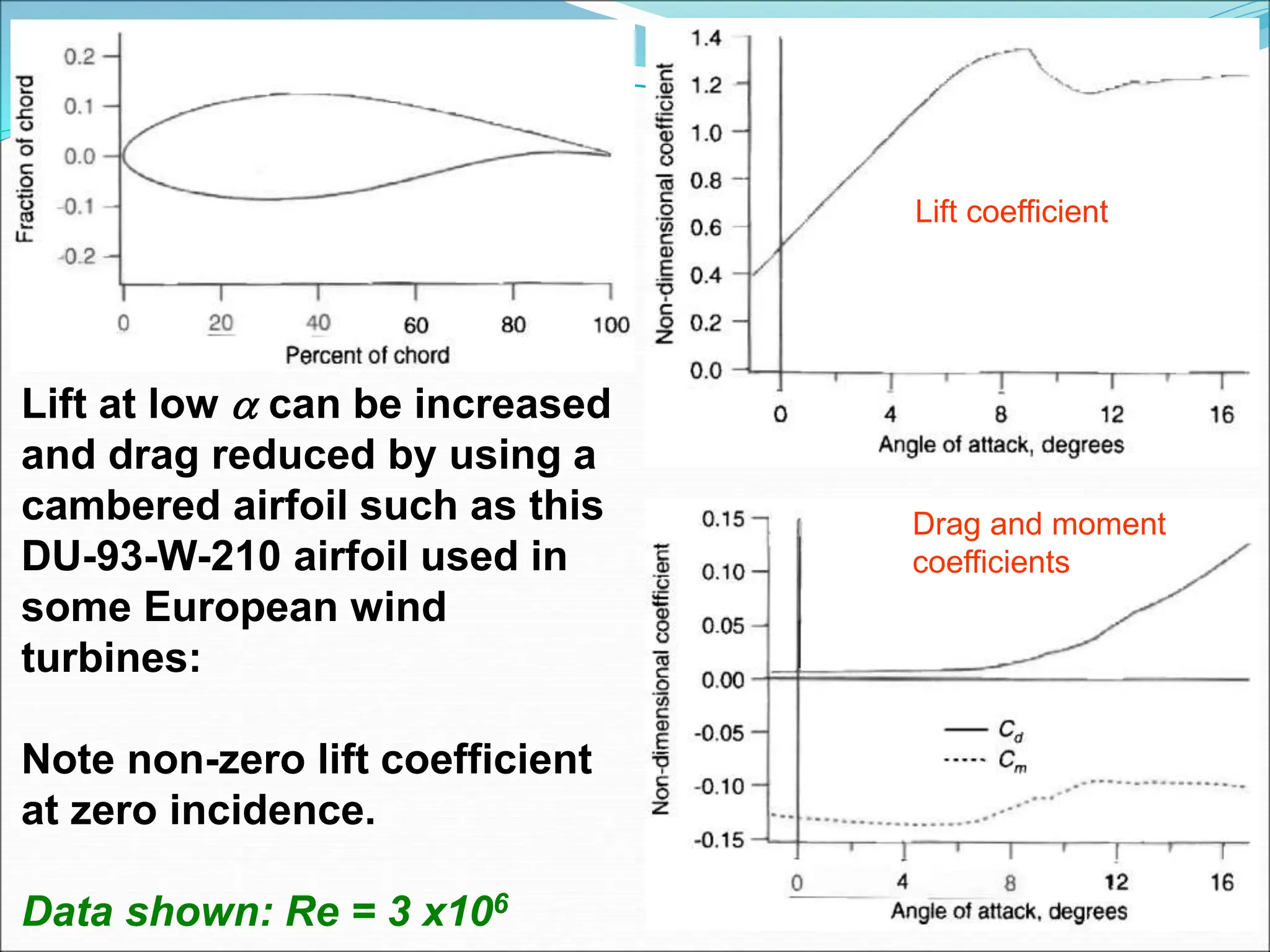
Lift at low  can be increased
and drag reduced by using a
cambered airfoil such as this
DU-93-W-210 airfoil used in
some European wind
turbines:
Note non-zero lift coefficient
at zero incidence.
Data shown: Re = 3 x10⁶
Lift coefficient
Drag and moment
coefficients
Another wind turbine airfoil profile: Lift and drag
coefficients for a S809 airfoil at Re = 7.5x10⁷
Attached flow regime:
At low  (up to about 7o for DU-93-W-210), flow is attached to
upper surface of the airfoil. In this regime, lift increases with 
and drag is relatively low.
High lift/stall development regime:
Here (from about 7-11o for DU-93-W-210), lift coeff peaks as airfoil
becomes increasingly stalled. Stall occurs when  exceeds a
critical value (10-16o, depending on Re) and separation of the
boundary layer on the upper surface occurs. This causes a wake
above the airfoil, reducing lift and increasing drag. This can occur
at certain blade locations or conditions of wind turbine operation.
It is sometimes used to limit wind turbine power in high winds.
For example, many designs using fixed pitch blades rely on
power regulation control via aerodynamic stall of the blades. That
is, as wind speed increases, stall progresses outboard along the
span of the blade (toward the tip) causing decreased lift and
increased drag. In a well designed, stall regulated machine, this
results in nearly constant power output as wind speeds increase.
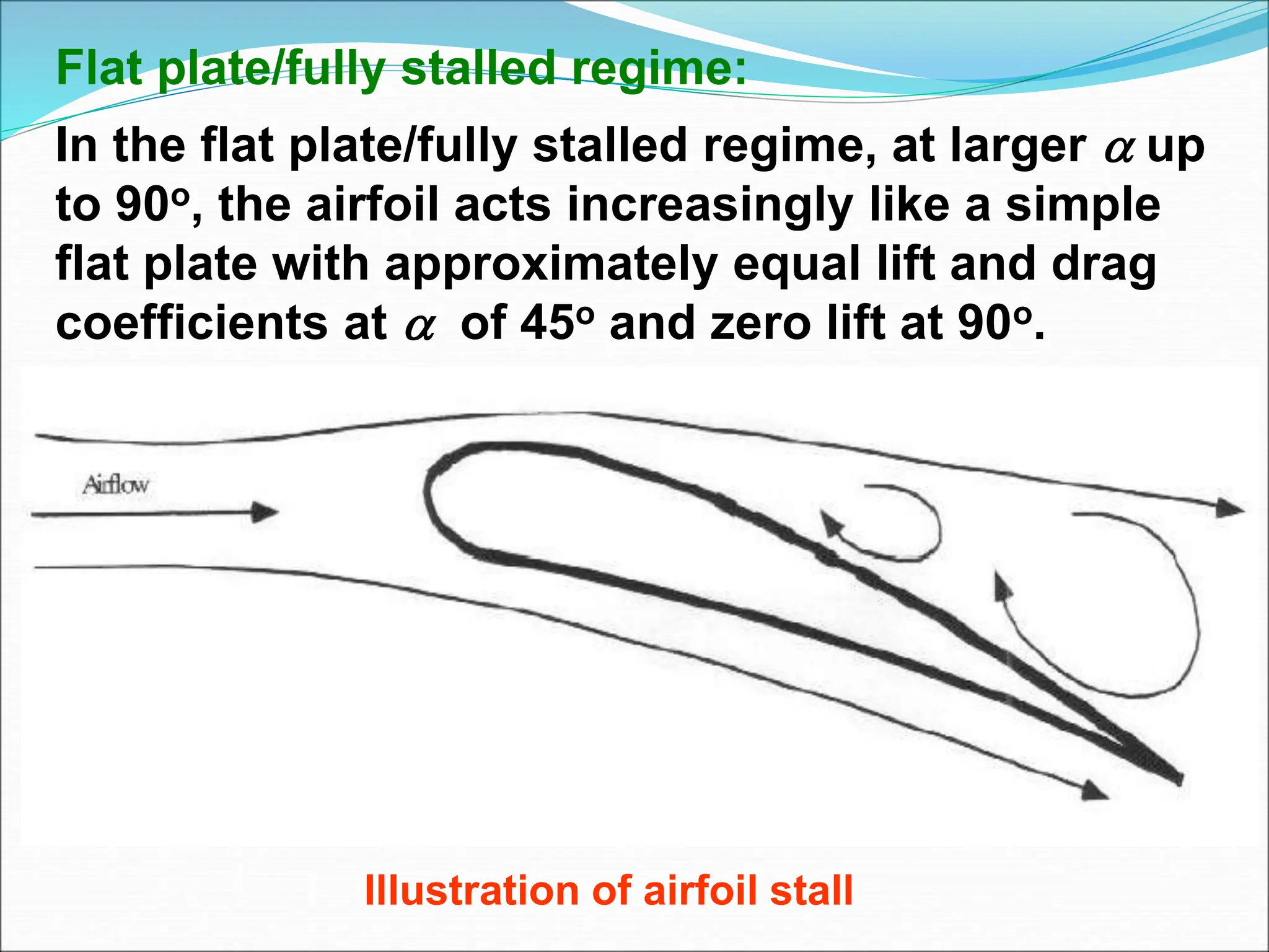
Flat plate/fully stalled regime:
In the flat plate/fully stalled regime, at larger  up
to 90o, the airfoil acts increasingly like a simple
flat plate with approximately equal lift and drag
coefficients at  of 45o and zero lift at 90o.
Illustration of airfoil stall
Airfoils for wind turbines
Typical blade chord Re range is 5 x 10⁵ – 1 x 10⁷
1970s and 1980s – designers thought airfoil
performance was less important than optimising
blade twist and taper.
Hence, helicopter blade sections, such as NACA
44xx and NACA 230xx, were popular as it was
viewed as a similar application (high max. lift, low
pitching moment, low min. drag).
But the following shortcomings have led to more
attention on improved airfoil design:
Operational experience showed shortcomings (e.g.
stall controlled HAWT produced too much power
in high winds, causing generator damage).
Turbines were operating with some part of the
blade in deep stall for more than 50% of the
lifetime of the machine.
Peak power and peak blade loads were occurring
while turbine was operating with most of the blade
stalled and predicted loads were 50 – 70% of the
measured loads!
Leading edge roughness affected rotor
performance. Insects and dirt  output dropped
by up to 40% of clean value!
Momentum theory and Blade Element theory
The actuator disk approach yields the pressure
change across the disk that is, in practice,
produced by blades.
This, and the axial and angular induction factors
that are a function of rotor power extraction and
thrust, will now be used to define the flow at the
airfoils.
The rotor geometry and its associated lift and drag
characteristics can then be used to determine
- rotor shape if some performance parameters are known, or
- rotor performance if the blade shape has been defined.
Analysis uses:
Momentum theory - CV analysis of the forces at
the blade based on the conservation of
linear and angular momentum.
Blade element theory – analysis of forces at a
section of the blade, as a function of blade
geometry.
Results combined into “strip theory” or blade
element momentum (BEM) theory.
This relates blade shape to the rotor's ability to
extract power from the wind.
Analysis encompasses:
- Momentum and blade element theory.
- The simplest 'optimum' blade design with an
infinite number of blades and no wake rotation.
- Performance characteristics (forces, rotor
airflow characteristics, power coefficient) for a
general blade design of known chord and twist
distribution, including wake rotation, drag, and
losses due to a finite number of blades.
- A simple 'optimum' blade design including wake
rotation and an infinite number of blades. This
blade design can be used as the start for a
general blade design analysis.
Momentum theory
We use the annular control volume, as before, with
induction factors (a, a’ ) being a function of radius r.
Similarly, from conservation of angular momentum,
the differential torque, Q, imparted to the blades
(and equally, but oppositely, to the air) is:
Together, these define thrust and torque on an
annular section of the rotor as functions of axial
and angular induction factors that represent the
flow conditions.
Applying linear momentum conservation to the
CV of radius r and thickness dr gives the thrust
contribution as:
Rotor Design
(Blade element theory)
The forces on the blades of a wind turbine can
also be expressed as a function of Cl , Cd and .
For this analysis, the blade is assumed to be
divided into N sections (or elements).
Assumptions:
- There is no aerodynamic interaction between
elements.
- The forces on the blades are determined solely
by the lift and drag characteristics of the
airfoil shape of the blades.
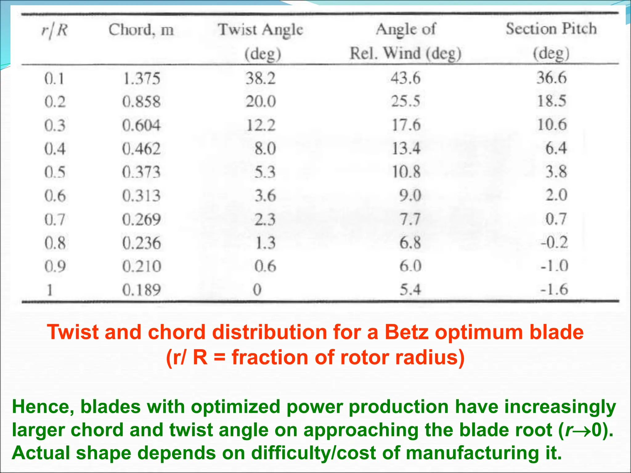
Diagram of blade elements
c = airfoil chord length; dr = radial length of element
r = radius; R = rotor radius;  = rotor angular velocity
Overall geometry for
a downwind HAWT
analysis; U = velocity
of undisturbed flow;
 = angular velocity
of rotor; a = axial
induction factor
Note:
Lift and drag forces are perpendicular and parallel,
respectively, to an effective, or relative, wind.
The relative wind is the vector sum of the wind
velocity at the rotor, U (1 - a), and the wind velocity
due to rotation of the blade.
This rotational component is the vector sum of the
blade section velocity,  r, and the induced angular
velocity at the blades from conservation of angular
momentum,  r / 2, or:
Rotor Design
(Blade element theory)
The air hits the blade in an angle α which is called the “angle of attack”. The
reference line” for the angle on the blade is most often “the chord line” .
The force on the blade F can be divided into two components – the lift force F L
and the drag force F D and the lift force is – per definition – perpendicular to the
wind direction.
Rotor Design
(Blade element theory)
The lift force is given as
And the drag force
The ratio GR=CL / CD is called the “glide ratio”,
Normally we are interested in at high glide ratio
for wind turbines as well as for air planes.
Rotor Design
(Blade element theory)
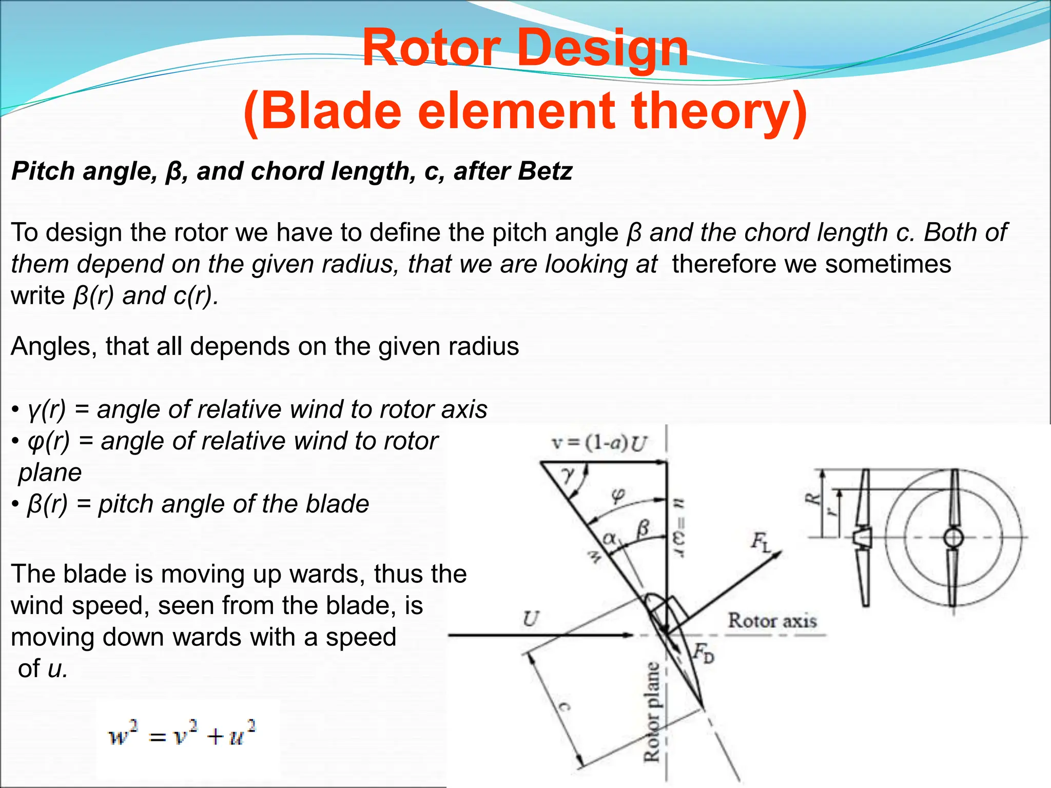
Pitch angle, β, and chord length, c, after Betz
To design the rotor we have to define the pitch angle β and the chord length c. Both of
them depend on the given radius, that we are looking at therefore we sometimes
write β(r) and c(r).
Angles, that all depends on the given radius
• γ(r) = angle of relative wind to rotor axis
• φ(r) = angle of relative wind to rotor
plane
• β(r) = pitch angle of the blade
The blade is moving up wards, thus the
wind speed, seen from the blade, is
moving down wards with a speed
of u.
Rotor Design
(Blade element theory)
Pitch angle, β, and chord length, c, after Betz
Betz does not include rotation of the wind (No Wakes). Therefore
Here ω is the angular speed of the rotor
R
U
 =
R
(1-a)U
(r) =tan-1
For a=1/3 3r
2R
(r) =tan-1
(r) = +
and
2R
3r
(r) =tan-1
The pitch angle (r) =tan-1 -
2R
3r
r
u 

Rotor Design
Pitch angle, β, and chord length, c, after Betz
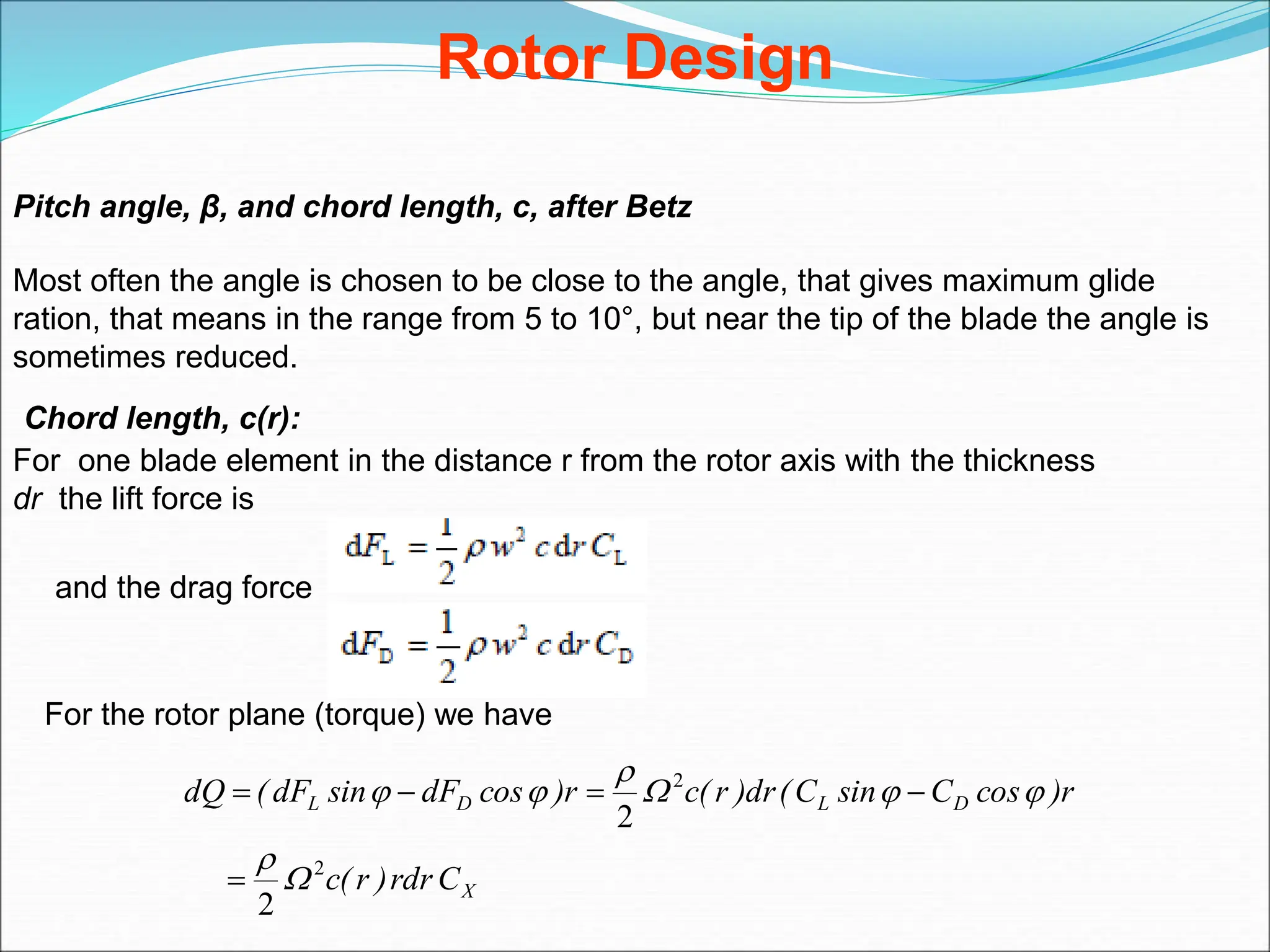
Most often the angle is chosen to be close to the angle, that gives maximum glide
ration, that means in the range from 5 to 10°, but near the tip of the blade the angle is
sometimes reduced.
Chord length, c(r):
For one blade element in the distance r from the rotor axis with the thickness
dr the lift force is
and the drag force
For the rotor plane (torque) we have
X
D
L
D
L
C
rdr
)
r
(
c
r
)
cos
C
sin
C
(
dr
)
r
(
c
r
)
cos
dF
sin
dF
(
dQ
2
2
2
2













Rotor Design
the thrust



sin
r
C
dr
)
r
(
c
dQ L
2
2

Now, in the design situation, we have C L >> CD
For N blades




sin
r
C
dr
)
r
(
c
N
dP L
2
2

According to Betz, the blade element would also give
)
rdr
(
U
N
A
U
)
a
(
a
dP 

 2
2
27
16
1
2
3
3
2



9
4
1
9
16
2
3
2
2










R
r
C
R
N
)
r
(
c
sin
r
u
,
cos
w
U
D
,
L






and
Using
Note: effect of drag is to decrease torque and,
hence, power, but to increase the thrust loading.
Thus, blade element theory gives 2 equations:
normal force (thrust) and tangential force (torque),
on the annular rotor section as a function of the flow
angles at the blades and airfoil characteristics.
These equations will be used to get blade shapes for
optimum performance and to find rotor performance
for an arbitrary shape.
Rotor Design
These equations may be used to find the chord
and twist distribution of the Betz optimum blade.
Example: Given  = 7, R = 5m, CL= 1, CD /CL is
minimum at  = 7, and there are 3 blades (N = 3)
we can use:
and
together with to obtain the changes
in chord, twist angle (= 0 at tip), angle of relative
wind, and section pitch, with radial distance, r/R,
along the blade:
2R
3r
(r) =tan-1
9
4
R
r
λ
λ
1
C
πR
9N
16
c(r)
2
2
D
L,








(r) = +
Twist and chord distribution for a Betz optimum blade
(r/ R = fraction of rotor radius)
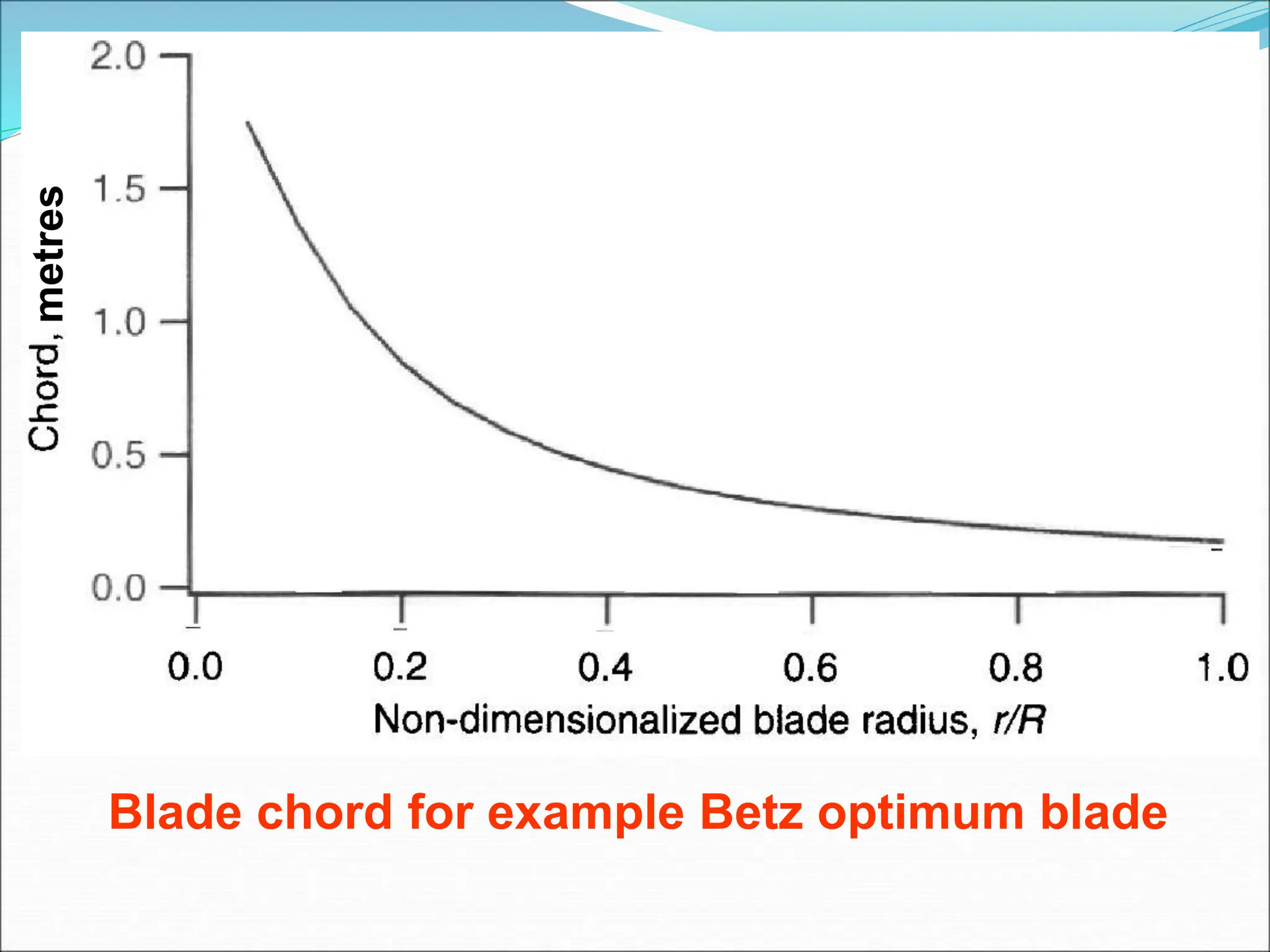
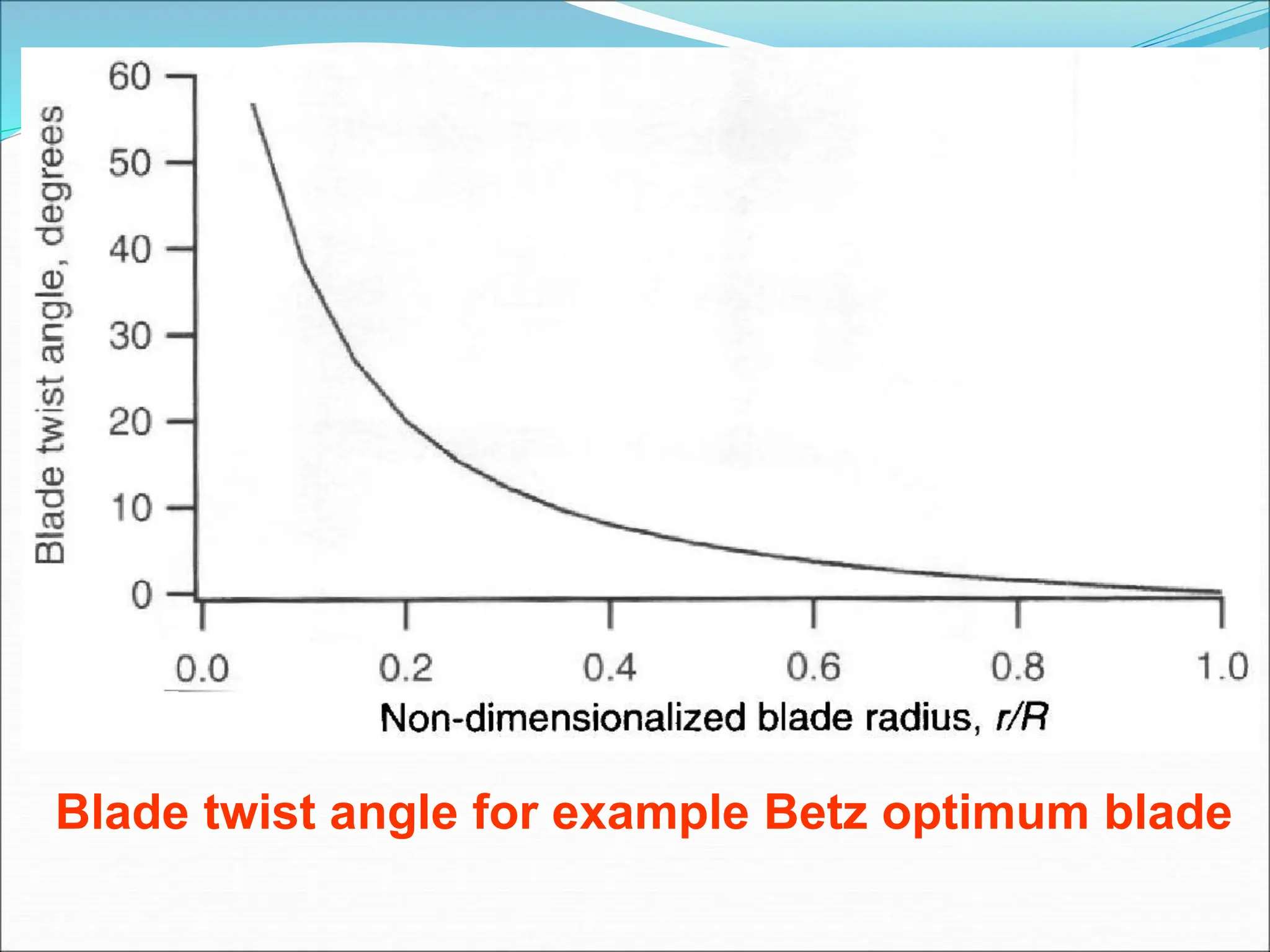
Hence, blades with optimized power production have increasingly
larger chord and twist angle on approaching the blade root (r0).
Actual shape depends on difficulty/cost of manufacturing it.
Blade chord for example Betz optimum blade
metres
Blade twist angle for example Betz optimum blade

More Related Content

What's hot

Wind turbine
Wind turbineWind turbine
Wind turbine
Roohul Amin
 
Control of wind turbines
Control of wind turbinesControl of wind turbines
Control of wind turbines
kybik-rybik
 
Wind turbine
Wind turbineWind turbine
Wind turbine
Bikram Dahal
 
Solar powered house
Solar powered houseSolar powered house
Solar powered house
Roshit Kadiru
 
Wind energy brief overview
Wind energy brief overviewWind energy brief overview
Wind energy brief overview
Mukit Ahmed Chowdhury
 
Energy storage systems for electric & hybrid vehicles
Energy storage systems for electric & hybrid vehiclesEnergy storage systems for electric & hybrid vehicles
Energy storage systems for electric & hybrid vehicles
College Of Engineering Pune
 
Wind Energy
Wind EnergyWind Energy
Wind Energy
Ratnesh Jaiswal
 
Wind Energy Lecture slides
Wind Energy Lecture slidesWind Energy Lecture slides
Wind Energy Lecture slides
Keith Vaugh
 
Solar power plant
Solar power plantSolar power plant
Solar power plant
Sindhu Nathan
 
Wind energy technology
Wind energy technologyWind energy technology
Wind energy technology
Taral Soliya
 
Powerpoint Presentation On WIND ENERGY
Powerpoint Presentation On WIND ENERGYPowerpoint Presentation On WIND ENERGY
Powerpoint Presentation On WIND ENERGY
Arunima Sethi
 
Floating wind turbine
Floating wind turbineFloating wind turbine
Floating wind turbine
ashokb27
 
ENERGY EFFICIENT MOTORS
ENERGY EFFICIENT MOTORSENERGY EFFICIENT MOTORS
ENERGY EFFICIENT MOTORS
Arigela Harika
 
WIND ENERGY SYSTEM
WIND ENERGY SYSTEM WIND ENERGY SYSTEM
WIND ENERGY SYSTEM
Power System Operation
 
Wind energy
Wind energyWind energy
Wind energy
sstms1
 
Wind power
Wind powerWind power
Wind power
Ahmed Nabil
 
Converter control in wind turbine
Converter control in wind turbineConverter control in wind turbine
Converter control in wind turbine
SonuKumarBairwa
 
Wind power
Wind powerWind power
Wind power
Sajida Shah
 
Wind physics
Wind physicsWind physics
Wind physics
SonuKumarBairwa
 
Solar photovoltaic technology
Solar photovoltaic technologySolar photovoltaic technology
Solar photovoltaic technology
Er Madhuri More
 

What's hot (20)

Wind turbine
Wind turbineWind turbine
Wind turbine
 
Control of wind turbines
Control of wind turbinesControl of wind turbines
Control of wind turbines
 
Wind turbine
Wind turbineWind turbine
Wind turbine
 
Solar powered house
Solar powered houseSolar powered house
Solar powered house
 
Wind energy brief overview
Wind energy brief overviewWind energy brief overview
Wind energy brief overview
 
Energy storage systems for electric & hybrid vehicles
Energy storage systems for electric & hybrid vehiclesEnergy storage systems for electric & hybrid vehicles
Energy storage systems for electric & hybrid vehicles
 
Wind Energy
Wind EnergyWind Energy
Wind Energy
 
Wind Energy Lecture slides
Wind Energy Lecture slidesWind Energy Lecture slides
Wind Energy Lecture slides
 
Solar power plant
Solar power plantSolar power plant
Solar power plant
 
Wind energy technology
Wind energy technologyWind energy technology
Wind energy technology
 
Powerpoint Presentation On WIND ENERGY
Powerpoint Presentation On WIND ENERGYPowerpoint Presentation On WIND ENERGY
Powerpoint Presentation On WIND ENERGY
 
Floating wind turbine
Floating wind turbineFloating wind turbine
Floating wind turbine
 
ENERGY EFFICIENT MOTORS
ENERGY EFFICIENT MOTORSENERGY EFFICIENT MOTORS
ENERGY EFFICIENT MOTORS
 
WIND ENERGY SYSTEM
WIND ENERGY SYSTEM WIND ENERGY SYSTEM
WIND ENERGY SYSTEM
 
Wind energy
Wind energyWind energy
Wind energy
 
Wind power
Wind powerWind power
Wind power
 
Converter control in wind turbine
Converter control in wind turbineConverter control in wind turbine
Converter control in wind turbine
 
Wind power
Wind powerWind power
Wind power
 
Wind physics
Wind physicsWind physics
Wind physics
 
Solar photovoltaic technology
Solar photovoltaic technologySolar photovoltaic technology
Solar photovoltaic technology
 

Similar to Aerodynamics of Wind Turbines - PART3.ppt

Aerodynamic,rotor design and rotor performance of horizontal axis wind turbin...
Aerodynamic,rotor design and rotor performance of horizontal axis wind turbin...Aerodynamic,rotor design and rotor performance of horizontal axis wind turbin...
Aerodynamic,rotor design and rotor performance of horizontal axis wind turbin...
Sarmad Adnan
 
CFD Analysis for Computing Drag force on Various types of blades for Vertical...
CFD Analysis for Computing Drag force on Various types of blades for Vertical...CFD Analysis for Computing Drag force on Various types of blades for Vertical...
CFD Analysis for Computing Drag force on Various types of blades for Vertical...
IRJET Journal
 
A Good Effect of Airfoil Design While Keeping Angle of Attack by 6 Degree
A Good Effect of Airfoil Design While Keeping Angle of Attack by 6 DegreeA Good Effect of Airfoil Design While Keeping Angle of Attack by 6 Degree
A Good Effect of Airfoil Design While Keeping Angle of Attack by 6 Degree
paperpublications3
 
CFD Analysis of a Three Bladed H-Rotor of Vertical Axis Wind Turbine
CFD Analysis of a Three Bladed H-Rotor of   Vertical Axis Wind Turbine CFD Analysis of a Three Bladed H-Rotor of   Vertical Axis Wind Turbine
CFD Analysis of a Three Bladed H-Rotor of Vertical Axis Wind Turbine
IRJET Journal
 
5_ISMTII2015_1281_VAWT_ShiehHsiao_et.al_manuscript_15Juli2015_vorlage
5_ISMTII2015_1281_VAWT_ShiehHsiao_et.al_manuscript_15Juli2015_vorlage5_ISMTII2015_1281_VAWT_ShiehHsiao_et.al_manuscript_15Juli2015_vorlage
5_ISMTII2015_1281_VAWT_ShiehHsiao_et.al_manuscript_15Juli2015_vorlage
Doug Yang-Hsu Liao
 
Numerical Analysis of Lift & Drag Performance of NACA0012 Wind Turbine Aerofoil
Numerical Analysis of Lift & Drag Performance of NACA0012 Wind Turbine AerofoilNumerical Analysis of Lift & Drag Performance of NACA0012 Wind Turbine Aerofoil
Numerical Analysis of Lift & Drag Performance of NACA0012 Wind Turbine Aerofoil
IRJET Journal
 
Review 4
Review 4Review 4
Review 4
Debarshi Sharma
 
C04571829
C04571829C04571829
C04571829
IOSR-JEN
 
E046403544
E046403544E046403544
E046403544
IOSR-JEN
 
J0341049054
J0341049054J0341049054
J0341049054
inventionjournals
 
Numerical Investigation Of Compression Performance Of Different Blade Configu...
Numerical Investigation Of Compression Performance Of Different Blade Configu...Numerical Investigation Of Compression Performance Of Different Blade Configu...
Numerical Investigation Of Compression Performance Of Different Blade Configu...
IJERA Editor
 
M505068995
M505068995M505068995
M505068995
IJERA Editor
 
Energy in wind
Energy in windEnergy in wind
Energy in wind
MUHAMMAD NASIR
 
IRJET-Subsonic Flow Study and Analysis on Rotating Cylinder Airfoil
IRJET-Subsonic Flow Study and Analysis on Rotating Cylinder AirfoilIRJET-Subsonic Flow Study and Analysis on Rotating Cylinder Airfoil
IRJET-Subsonic Flow Study and Analysis on Rotating Cylinder Airfoil
IRJET Journal
 
IRJET- Investigation of Effects of Trailing Edge Geometry on Vertical Axis Wi...
IRJET- Investigation of Effects of Trailing Edge Geometry on Vertical Axis Wi...IRJET- Investigation of Effects of Trailing Edge Geometry on Vertical Axis Wi...
IRJET- Investigation of Effects of Trailing Edge Geometry on Vertical Axis Wi...
IRJET Journal
 
2. article azojete vol 11 13 23 ngala
2. article azojete vol 11 13 23 ngala2. article azojete vol 11 13 23 ngala
2. article azojete vol 11 13 23 ngala
Oyeniyi Samuel
 
Project Report on 'Modulation of Vertical Axis Wind Turbine'
Project Report on 'Modulation of Vertical Axis Wind Turbine'Project Report on 'Modulation of Vertical Axis Wind Turbine'
Project Report on 'Modulation of Vertical Axis Wind Turbine'
Gurpreet Singh Chhabda
 
AERODYNAMICS FORCES AND MOMENTS.ppt
AERODYNAMICS FORCES AND MOMENTS.pptAERODYNAMICS FORCES AND MOMENTS.ppt
AERODYNAMICS FORCES AND MOMENTS.ppt
tauraimamire
 
IRJET- CFD Approach of Joukowski Airfoil (T=12%), Comparison of its Aerodynam...
IRJET- CFD Approach of Joukowski Airfoil (T=12%), Comparison of its Aerodynam...IRJET- CFD Approach of Joukowski Airfoil (T=12%), Comparison of its Aerodynam...
IRJET- CFD Approach of Joukowski Airfoil (T=12%), Comparison of its Aerodynam...
IRJET Journal
 
International Journal of Engineering Research and Development
International Journal of Engineering Research and DevelopmentInternational Journal of Engineering Research and Development
International Journal of Engineering Research and Development
IJERD Editor
 

Similar to Aerodynamics of Wind Turbines - PART3.ppt (20)

Aerodynamic,rotor design and rotor performance of horizontal axis wind turbin...
Aerodynamic,rotor design and rotor performance of horizontal axis wind turbin...Aerodynamic,rotor design and rotor performance of horizontal axis wind turbin...
Aerodynamic,rotor design and rotor performance of horizontal axis wind turbin...
 
CFD Analysis for Computing Drag force on Various types of blades for Vertical...
CFD Analysis for Computing Drag force on Various types of blades for Vertical...CFD Analysis for Computing Drag force on Various types of blades for Vertical...
CFD Analysis for Computing Drag force on Various types of blades for Vertical...
 
A Good Effect of Airfoil Design While Keeping Angle of Attack by 6 Degree
A Good Effect of Airfoil Design While Keeping Angle of Attack by 6 DegreeA Good Effect of Airfoil Design While Keeping Angle of Attack by 6 Degree
A Good Effect of Airfoil Design While Keeping Angle of Attack by 6 Degree
 
CFD Analysis of a Three Bladed H-Rotor of Vertical Axis Wind Turbine
CFD Analysis of a Three Bladed H-Rotor of   Vertical Axis Wind Turbine CFD Analysis of a Three Bladed H-Rotor of   Vertical Axis Wind Turbine
CFD Analysis of a Three Bladed H-Rotor of Vertical Axis Wind Turbine
 
5_ISMTII2015_1281_VAWT_ShiehHsiao_et.al_manuscript_15Juli2015_vorlage
5_ISMTII2015_1281_VAWT_ShiehHsiao_et.al_manuscript_15Juli2015_vorlage5_ISMTII2015_1281_VAWT_ShiehHsiao_et.al_manuscript_15Juli2015_vorlage
5_ISMTII2015_1281_VAWT_ShiehHsiao_et.al_manuscript_15Juli2015_vorlage
 
Numerical Analysis of Lift & Drag Performance of NACA0012 Wind Turbine Aerofoil
Numerical Analysis of Lift & Drag Performance of NACA0012 Wind Turbine AerofoilNumerical Analysis of Lift & Drag Performance of NACA0012 Wind Turbine Aerofoil
Numerical Analysis of Lift & Drag Performance of NACA0012 Wind Turbine Aerofoil
 
Review 4
Review 4Review 4
Review 4
 
C04571829
C04571829C04571829
C04571829
 
E046403544
E046403544E046403544
E046403544
 
J0341049054
J0341049054J0341049054
J0341049054
 
Numerical Investigation Of Compression Performance Of Different Blade Configu...
Numerical Investigation Of Compression Performance Of Different Blade Configu...Numerical Investigation Of Compression Performance Of Different Blade Configu...
Numerical Investigation Of Compression Performance Of Different Blade Configu...
 
M505068995
M505068995M505068995
M505068995
 
Energy in wind
Energy in windEnergy in wind
Energy in wind
 
IRJET-Subsonic Flow Study and Analysis on Rotating Cylinder Airfoil
IRJET-Subsonic Flow Study and Analysis on Rotating Cylinder AirfoilIRJET-Subsonic Flow Study and Analysis on Rotating Cylinder Airfoil
IRJET-Subsonic Flow Study and Analysis on Rotating Cylinder Airfoil
 
IRJET- Investigation of Effects of Trailing Edge Geometry on Vertical Axis Wi...
IRJET- Investigation of Effects of Trailing Edge Geometry on Vertical Axis Wi...IRJET- Investigation of Effects of Trailing Edge Geometry on Vertical Axis Wi...
IRJET- Investigation of Effects of Trailing Edge Geometry on Vertical Axis Wi...
 
2. article azojete vol 11 13 23 ngala
2. article azojete vol 11 13 23 ngala2. article azojete vol 11 13 23 ngala
2. article azojete vol 11 13 23 ngala
 
Project Report on 'Modulation of Vertical Axis Wind Turbine'
Project Report on 'Modulation of Vertical Axis Wind Turbine'Project Report on 'Modulation of Vertical Axis Wind Turbine'
Project Report on 'Modulation of Vertical Axis Wind Turbine'
 
AERODYNAMICS FORCES AND MOMENTS.ppt
AERODYNAMICS FORCES AND MOMENTS.pptAERODYNAMICS FORCES AND MOMENTS.ppt
AERODYNAMICS FORCES AND MOMENTS.ppt
 
IRJET- CFD Approach of Joukowski Airfoil (T=12%), Comparison of its Aerodynam...
IRJET- CFD Approach of Joukowski Airfoil (T=12%), Comparison of its Aerodynam...IRJET- CFD Approach of Joukowski Airfoil (T=12%), Comparison of its Aerodynam...
IRJET- CFD Approach of Joukowski Airfoil (T=12%), Comparison of its Aerodynam...
 
International Journal of Engineering Research and Development
International Journal of Engineering Research and DevelopmentInternational Journal of Engineering Research and Development
International Journal of Engineering Research and Development
 

Recently uploaded

Applications of artificial Intelligence in Mechanical Engineering.pdf
Applications of artificial Intelligence in Mechanical Engineering.pdfApplications of artificial Intelligence in Mechanical Engineering.pdf
Applications of artificial Intelligence in Mechanical Engineering.pdf
Atif Razi
 
学校原版美国波士顿大学毕业证学历学位证书原版一模一样
学校原版美国波士顿大学毕业证学历学位证书原版一模一样学校原版美国波士顿大学毕业证学历学位证书原版一模一样
学校原版美国波士顿大学毕业证学历学位证书原版一模一样
171ticu
 
Material for memory and display system h
Material for memory and display system hMaterial for memory and display system h
Material for memory and display system h
gowrishankartb2005
 
Null Bangalore | Pentesters Approach to AWS IAM
Null Bangalore | Pentesters Approach to AWS IAMNull Bangalore | Pentesters Approach to AWS IAM
Null Bangalore | Pentesters Approach to AWS IAM
Divyanshu
 
CompEx~Manual~1210 (2).pdf COMPEX GAS AND VAPOURS
CompEx~Manual~1210 (2).pdf COMPEX GAS AND VAPOURSCompEx~Manual~1210 (2).pdf COMPEX GAS AND VAPOURS
CompEx~Manual~1210 (2).pdf COMPEX GAS AND VAPOURS
RamonNovais6
 
Embedded machine learning-based road conditions and driving behavior monitoring
Embedded machine learning-based road conditions and driving behavior monitoringEmbedded machine learning-based road conditions and driving behavior monitoring
Embedded machine learning-based road conditions and driving behavior monitoring
IJECEIAES
 
CEC 352 - SATELLITE COMMUNICATION UNIT 1
CEC 352 - SATELLITE COMMUNICATION UNIT 1CEC 352 - SATELLITE COMMUNICATION UNIT 1
CEC 352 - SATELLITE COMMUNICATION UNIT 1
PKavitha10
 
An improved modulation technique suitable for a three level flying capacitor ...
An improved modulation technique suitable for a three level flying capacitor ...An improved modulation technique suitable for a three level flying capacitor ...
An improved modulation technique suitable for a three level flying capacitor ...
IJECEIAES
 
LLM Fine Tuning with QLoRA Cassandra Lunch 4, presented by Anant
LLM Fine Tuning with QLoRA Cassandra Lunch 4, presented by AnantLLM Fine Tuning with QLoRA Cassandra Lunch 4, presented by Anant
LLM Fine Tuning with QLoRA Cassandra Lunch 4, presented by Anant
Anant Corporation
 
Data Driven Maintenance | UReason Webinar
Data Driven Maintenance | UReason WebinarData Driven Maintenance | UReason Webinar
Data Driven Maintenance | UReason Webinar
UReason
 
BRAIN TUMOR DETECTION for seminar ppt.pdf
BRAIN TUMOR DETECTION for seminar ppt.pdfBRAIN TUMOR DETECTION for seminar ppt.pdf
BRAIN TUMOR DETECTION for seminar ppt.pdf
LAXMAREDDY22
 
Optimizing Gradle Builds - Gradle DPE Tour Berlin 2024
Optimizing Gradle Builds - Gradle DPE Tour Berlin 2024Optimizing Gradle Builds - Gradle DPE Tour Berlin 2024
Optimizing Gradle Builds - Gradle DPE Tour Berlin 2024
Sinan KOZAK
 
Software Engineering and Project Management - Introduction, Modeling Concepts...
Software Engineering and Project Management - Introduction, Modeling Concepts...Software Engineering and Project Management - Introduction, Modeling Concepts...
Software Engineering and Project Management - Introduction, Modeling Concepts...
Prakhyath Rai
 
Properties Railway Sleepers and Test.pptx
Properties Railway Sleepers and Test.pptxProperties Railway Sleepers and Test.pptx
Properties Railway Sleepers and Test.pptx
MDSABBIROJJAMANPAYEL
 
哪里办理(csu毕业证书)查尔斯特大学毕业证硕士学历原版一模一样
哪里办理(csu毕业证书)查尔斯特大学毕业证硕士学历原版一模一样哪里办理(csu毕业证书)查尔斯特大学毕业证硕士学历原版一模一样
哪里办理(csu毕业证书)查尔斯特大学毕业证硕士学历原版一模一样
insn4465
 
artificial intelligence and data science contents.pptx
artificial intelligence and data science contents.pptxartificial intelligence and data science contents.pptx
artificial intelligence and data science contents.pptx
GauravCar
 
Advanced control scheme of doubly fed induction generator for wind turbine us...
Advanced control scheme of doubly fed induction generator for wind turbine us...Advanced control scheme of doubly fed induction generator for wind turbine us...
Advanced control scheme of doubly fed induction generator for wind turbine us...
IJECEIAES
 
Software Quality Assurance-se412-v11.ppt
Software Quality Assurance-se412-v11.pptSoftware Quality Assurance-se412-v11.ppt
Software Quality Assurance-se412-v11.ppt
TaghreedAltamimi
 
Use PyCharm for remote debugging of WSL on a Windo cf5c162d672e4e58b4dde5d797...
Use PyCharm for remote debugging of WSL on a Windo cf5c162d672e4e58b4dde5d797...Use PyCharm for remote debugging of WSL on a Windo cf5c162d672e4e58b4dde5d797...
Use PyCharm for remote debugging of WSL on a Windo cf5c162d672e4e58b4dde5d797...
shadow0702a
 
Comparative analysis between traditional aquaponics and reconstructed aquapon...
Comparative analysis between traditional aquaponics and reconstructed aquapon...Comparative analysis between traditional aquaponics and reconstructed aquapon...
Comparative analysis between traditional aquaponics and reconstructed aquapon...
bijceesjournal
 

Recently uploaded (20)

Applications of artificial Intelligence in Mechanical Engineering.pdf
Applications of artificial Intelligence in Mechanical Engineering.pdfApplications of artificial Intelligence in Mechanical Engineering.pdf
Applications of artificial Intelligence in Mechanical Engineering.pdf
 
学校原版美国波士顿大学毕业证学历学位证书原版一模一样
学校原版美国波士顿大学毕业证学历学位证书原版一模一样学校原版美国波士顿大学毕业证学历学位证书原版一模一样
学校原版美国波士顿大学毕业证学历学位证书原版一模一样
 
Material for memory and display system h
Material for memory and display system hMaterial for memory and display system h
Material for memory and display system h
 
Null Bangalore | Pentesters Approach to AWS IAM
Null Bangalore | Pentesters Approach to AWS IAMNull Bangalore | Pentesters Approach to AWS IAM
Null Bangalore | Pentesters Approach to AWS IAM
 
CompEx~Manual~1210 (2).pdf COMPEX GAS AND VAPOURS
CompEx~Manual~1210 (2).pdf COMPEX GAS AND VAPOURSCompEx~Manual~1210 (2).pdf COMPEX GAS AND VAPOURS
CompEx~Manual~1210 (2).pdf COMPEX GAS AND VAPOURS
 
Embedded machine learning-based road conditions and driving behavior monitoring
Embedded machine learning-based road conditions and driving behavior monitoringEmbedded machine learning-based road conditions and driving behavior monitoring
Embedded machine learning-based road conditions and driving behavior monitoring
 
CEC 352 - SATELLITE COMMUNICATION UNIT 1
CEC 352 - SATELLITE COMMUNICATION UNIT 1CEC 352 - SATELLITE COMMUNICATION UNIT 1
CEC 352 - SATELLITE COMMUNICATION UNIT 1
 
An improved modulation technique suitable for a three level flying capacitor ...
An improved modulation technique suitable for a three level flying capacitor ...An improved modulation technique suitable for a three level flying capacitor ...
An improved modulation technique suitable for a three level flying capacitor ...
 
LLM Fine Tuning with QLoRA Cassandra Lunch 4, presented by Anant
LLM Fine Tuning with QLoRA Cassandra Lunch 4, presented by AnantLLM Fine Tuning with QLoRA Cassandra Lunch 4, presented by Anant
LLM Fine Tuning with QLoRA Cassandra Lunch 4, presented by Anant
 
Data Driven Maintenance | UReason Webinar
Data Driven Maintenance | UReason WebinarData Driven Maintenance | UReason Webinar
Data Driven Maintenance | UReason Webinar
 
BRAIN TUMOR DETECTION for seminar ppt.pdf
BRAIN TUMOR DETECTION for seminar ppt.pdfBRAIN TUMOR DETECTION for seminar ppt.pdf
BRAIN TUMOR DETECTION for seminar ppt.pdf
 
Optimizing Gradle Builds - Gradle DPE Tour Berlin 2024
Optimizing Gradle Builds - Gradle DPE Tour Berlin 2024Optimizing Gradle Builds - Gradle DPE Tour Berlin 2024
Optimizing Gradle Builds - Gradle DPE Tour Berlin 2024
 
Software Engineering and Project Management - Introduction, Modeling Concepts...
Software Engineering and Project Management - Introduction, Modeling Concepts...Software Engineering and Project Management - Introduction, Modeling Concepts...
Software Engineering and Project Management - Introduction, Modeling Concepts...
 
Properties Railway Sleepers and Test.pptx
Properties Railway Sleepers and Test.pptxProperties Railway Sleepers and Test.pptx
Properties Railway Sleepers and Test.pptx
 
哪里办理(csu毕业证书)查尔斯特大学毕业证硕士学历原版一模一样
哪里办理(csu毕业证书)查尔斯特大学毕业证硕士学历原版一模一样哪里办理(csu毕业证书)查尔斯特大学毕业证硕士学历原版一模一样
哪里办理(csu毕业证书)查尔斯特大学毕业证硕士学历原版一模一样
 
artificial intelligence and data science contents.pptx
artificial intelligence and data science contents.pptxartificial intelligence and data science contents.pptx
artificial intelligence and data science contents.pptx
 
Advanced control scheme of doubly fed induction generator for wind turbine us...
Advanced control scheme of doubly fed induction generator for wind turbine us...Advanced control scheme of doubly fed induction generator for wind turbine us...
Advanced control scheme of doubly fed induction generator for wind turbine us...
 
Software Quality Assurance-se412-v11.ppt
Software Quality Assurance-se412-v11.pptSoftware Quality Assurance-se412-v11.ppt
Software Quality Assurance-se412-v11.ppt
 
Use PyCharm for remote debugging of WSL on a Windo cf5c162d672e4e58b4dde5d797...
Use PyCharm for remote debugging of WSL on a Windo cf5c162d672e4e58b4dde5d797...Use PyCharm for remote debugging of WSL on a Windo cf5c162d672e4e58b4dde5d797...
Use PyCharm for remote debugging of WSL on a Windo cf5c162d672e4e58b4dde5d797...
 
Comparative analysis between traditional aquaponics and reconstructed aquapon...
Comparative analysis between traditional aquaponics and reconstructed aquapon...Comparative analysis between traditional aquaponics and reconstructed aquapon...
Comparative analysis between traditional aquaponics and reconstructed aquapon...
 

Aerodynamics of Wind Turbines - PART3.ppt

  • 1. Aerodynamics of Wind Turbines Part -3
  • 2. Airfoils and general aerodynamic concepts Wind turbine blades use airfoil sections to develop mechanical power. The width and length of the blades are a function of the desired aerodynamic performance and the maximum desired rotor power (as well as strength considerations). Before examining the details of wind turbine power production, some airfoil aerodynamic principles are reviewed here.
  • 3. Basic airfoil terminology Camber = distance between mean camber line (mid-point of airfoil) and the chord line (straight line from leading edge to trailing edge) Thickness = distance between upper and lower surfaces (measured perpendicular to chord line) Span = length of airfoil normal to the cross-section Camber Thickness
  • 4. Examples of standard airfoil shapes National Advisory Committee for Aeronautics NACA 0012 = 12% thick symmetric airfoil NACA 63(2)-215 = 15% thick airfoil with slight camber LS(1)-0417 = 17% thick airfoil with larger camber
  • 5. Lift, drag and non-dimensional parameters Airflow over an airfoil produces a distribution of forces over the airfoil surface. The flow velocity over airfoils increases over the convex surface resulting in lower average pressure on the 'suction' side of the airfoil compared with the concave or 'pressure' side of the airfoil. Meanwhile, viscous friction between the air and the airfoil surface slows the airflow to some extent next to the surface.
  • 6. Lift force - defined to be perpendicular to direction of the oncoming airflow. The lift force is a consequence of the unequal pressure on the upper and lower airfoil surfaces Drag force - defined to be parallel to the direction of oncoming airflow. The drag force is due both to viscous friction forces at the surface of the airfoil and to unequal pressure on the airfoil surfaces facing toward and away from the oncoming flow Pitching moment - defined to be about an axis perpendicular to the airfoil cross-section
  • 7. The resultant of all of these pressure and friction forces is usually resolved into two forces and a moment that act along the chord at c / 4 from the leading edge (at the 'quarter chord'). These forces are a function of Reynolds number Re = U L /  (L is a characteristic length, e.g. c) Velocity = U
  • 8. The 2-D airfoil section lift, drag and pitching moment coefficients are normally defined as: A = projected airfoil area = chord x span = c l
  • 9. Other dimensionless parameters that are important for analysis and design of wind turbines include the power and thrust coefficients and tip speed ratio, mentioned earlier and also the pressure coefficient: and blade surface roughness ratio:
  • 10. Airfoil aerodynamic behaviour The theoretical lift coefficient for a flat plate is: which is also a good approximation for real, thin airfoils, but only for small  . Lift and drag coefficients for a NACA 0012 airfoil as a function of  and Re  
  • 11. Airfoils for HAWT are often designed to be used at low angles of attack, where lift coefficients are fairly high and drag coefficients are fairly low. The lift coefficient of this symmetric airfoil is about zero at an angle of attack of zero and increases to over 1.0 before decreasing at higher angles of attack. The drag coefficient is usually much lower than the lift coefficient at low angles of attack. It increases at higher angles of attack. Note the significant differences in airfoil behaviour at different Re. Rotor designers must make sure that appropriate Re data are available for analysis.
  • 12. Lift at low  can be increased and drag reduced by using a cambered airfoil such as this DU-93-W-210 airfoil used in some European wind turbines: Note non-zero lift coefficient at zero incidence. Data shown: Re = 3 x10⁶ Lift coefficient Drag and moment coefficients
  • 13. Another wind turbine airfoil profile: Lift and drag coefficients for a S809 airfoil at Re = 7.5x10⁷
  • 14. Attached flow regime: At low  (up to about 7o for DU-93-W-210), flow is attached to upper surface of the airfoil. In this regime, lift increases with  and drag is relatively low. High lift/stall development regime: Here (from about 7-11o for DU-93-W-210), lift coeff peaks as airfoil becomes increasingly stalled. Stall occurs when  exceeds a critical value (10-16o, depending on Re) and separation of the boundary layer on the upper surface occurs. This causes a wake above the airfoil, reducing lift and increasing drag. This can occur at certain blade locations or conditions of wind turbine operation. It is sometimes used to limit wind turbine power in high winds. For example, many designs using fixed pitch blades rely on power regulation control via aerodynamic stall of the blades. That is, as wind speed increases, stall progresses outboard along the span of the blade (toward the tip) causing decreased lift and increased drag. In a well designed, stall regulated machine, this results in nearly constant power output as wind speeds increase.
  • 15. Flat plate/fully stalled regime: In the flat plate/fully stalled regime, at larger  up to 90o, the airfoil acts increasingly like a simple flat plate with approximately equal lift and drag coefficients at  of 45o and zero lift at 90o. Illustration of airfoil stall
  • 16. Airfoils for wind turbines Typical blade chord Re range is 5 x 10⁵ – 1 x 10⁷ 1970s and 1980s – designers thought airfoil performance was less important than optimising blade twist and taper. Hence, helicopter blade sections, such as NACA 44xx and NACA 230xx, were popular as it was viewed as a similar application (high max. lift, low pitching moment, low min. drag). But the following shortcomings have led to more attention on improved airfoil design:
  • 17. Operational experience showed shortcomings (e.g. stall controlled HAWT produced too much power in high winds, causing generator damage). Turbines were operating with some part of the blade in deep stall for more than 50% of the lifetime of the machine. Peak power and peak blade loads were occurring while turbine was operating with most of the blade stalled and predicted loads were 50 – 70% of the measured loads! Leading edge roughness affected rotor performance. Insects and dirt  output dropped by up to 40% of clean value!
  • 18. Momentum theory and Blade Element theory The actuator disk approach yields the pressure change across the disk that is, in practice, produced by blades. This, and the axial and angular induction factors that are a function of rotor power extraction and thrust, will now be used to define the flow at the airfoils. The rotor geometry and its associated lift and drag characteristics can then be used to determine - rotor shape if some performance parameters are known, or - rotor performance if the blade shape has been defined.
  • 19. Analysis uses: Momentum theory - CV analysis of the forces at the blade based on the conservation of linear and angular momentum. Blade element theory – analysis of forces at a section of the blade, as a function of blade geometry. Results combined into “strip theory” or blade element momentum (BEM) theory. This relates blade shape to the rotor's ability to extract power from the wind.
  • 20. Analysis encompasses: - Momentum and blade element theory. - The simplest 'optimum' blade design with an infinite number of blades and no wake rotation. - Performance characteristics (forces, rotor airflow characteristics, power coefficient) for a general blade design of known chord and twist distribution, including wake rotation, drag, and losses due to a finite number of blades. - A simple 'optimum' blade design including wake rotation and an infinite number of blades. This blade design can be used as the start for a general blade design analysis.
  • 21. Momentum theory We use the annular control volume, as before, with induction factors (a, a’ ) being a function of radius r.
  • 22. Similarly, from conservation of angular momentum, the differential torque, Q, imparted to the blades (and equally, but oppositely, to the air) is: Together, these define thrust and torque on an annular section of the rotor as functions of axial and angular induction factors that represent the flow conditions. Applying linear momentum conservation to the CV of radius r and thickness dr gives the thrust contribution as:
  • 23. Rotor Design (Blade element theory) The forces on the blades of a wind turbine can also be expressed as a function of Cl , Cd and . For this analysis, the blade is assumed to be divided into N sections (or elements). Assumptions: - There is no aerodynamic interaction between elements. - The forces on the blades are determined solely by the lift and drag characteristics of the airfoil shape of the blades.
  • 24. Diagram of blade elements c = airfoil chord length; dr = radial length of element r = radius; R = rotor radius;  = rotor angular velocity
  • 25. Overall geometry for a downwind HAWT analysis; U = velocity of undisturbed flow;  = angular velocity of rotor; a = axial induction factor
  • 26. Note: Lift and drag forces are perpendicular and parallel, respectively, to an effective, or relative, wind. The relative wind is the vector sum of the wind velocity at the rotor, U (1 - a), and the wind velocity due to rotation of the blade. This rotational component is the vector sum of the blade section velocity,  r, and the induced angular velocity at the blades from conservation of angular momentum,  r / 2, or:
  • 27. Rotor Design (Blade element theory) The air hits the blade in an angle α which is called the “angle of attack”. The reference line” for the angle on the blade is most often “the chord line” . The force on the blade F can be divided into two components – the lift force F L and the drag force F D and the lift force is – per definition – perpendicular to the wind direction.
  • 28. Rotor Design (Blade element theory) The lift force is given as And the drag force The ratio GR=CL / CD is called the “glide ratio”, Normally we are interested in at high glide ratio for wind turbines as well as for air planes.
  • 29. Rotor Design (Blade element theory) Pitch angle, β, and chord length, c, after Betz To design the rotor we have to define the pitch angle β and the chord length c. Both of them depend on the given radius, that we are looking at therefore we sometimes write β(r) and c(r). Angles, that all depends on the given radius • γ(r) = angle of relative wind to rotor axis • φ(r) = angle of relative wind to rotor plane • β(r) = pitch angle of the blade The blade is moving up wards, thus the wind speed, seen from the blade, is moving down wards with a speed of u.
  • 30. Rotor Design (Blade element theory) Pitch angle, β, and chord length, c, after Betz Betz does not include rotation of the wind (No Wakes). Therefore Here ω is the angular speed of the rotor R U  = R (1-a)U (r) =tan-1 For a=1/3 3r 2R (r) =tan-1 (r) = + and 2R 3r (r) =tan-1 The pitch angle (r) =tan-1 - 2R 3r r u  
  • 31. Rotor Design Pitch angle, β, and chord length, c, after Betz Most often the angle is chosen to be close to the angle, that gives maximum glide ration, that means in the range from 5 to 10°, but near the tip of the blade the angle is sometimes reduced. Chord length, c(r): For one blade element in the distance r from the rotor axis with the thickness dr the lift force is and the drag force For the rotor plane (torque) we have X D L D L C rdr ) r ( c r ) cos C sin C ( dr ) r ( c r ) cos dF sin dF ( dQ 2 2 2 2             
  • 32. Rotor Design the thrust    sin r C dr ) r ( c dQ L 2 2  Now, in the design situation, we have C L >> CD For N blades     sin r C dr ) r ( c N dP L 2 2  According to Betz, the blade element would also give ) rdr ( U N A U ) a ( a dP    2 2 27 16 1 2 3 3 2    9 4 1 9 16 2 3 2 2           R r C R N ) r ( c sin r u , cos w U D , L       and Using
  • 33. Note: effect of drag is to decrease torque and, hence, power, but to increase the thrust loading. Thus, blade element theory gives 2 equations: normal force (thrust) and tangential force (torque), on the annular rotor section as a function of the flow angles at the blades and airfoil characteristics. These equations will be used to get blade shapes for optimum performance and to find rotor performance for an arbitrary shape. Rotor Design
  • 34. These equations may be used to find the chord and twist distribution of the Betz optimum blade. Example: Given  = 7, R = 5m, CL= 1, CD /CL is minimum at  = 7, and there are 3 blades (N = 3) we can use: and together with to obtain the changes in chord, twist angle (= 0 at tip), angle of relative wind, and section pitch, with radial distance, r/R, along the blade: 2R 3r (r) =tan-1 9 4 R r λ λ 1 C πR 9N 16 c(r) 2 2 D L,         (r) = +
  • 35. Twist and chord distribution for a Betz optimum blade (r/ R = fraction of rotor radius) Hence, blades with optimized power production have increasingly larger chord and twist angle on approaching the blade root (r0). Actual shape depends on difficulty/cost of manufacturing it.
  • 36. Blade chord for example Betz optimum blade metres
  • 37. Blade twist angle for example Betz optimum blade