Downloaded 260 times
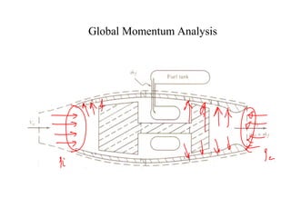
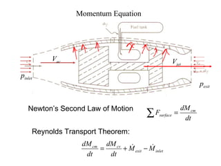
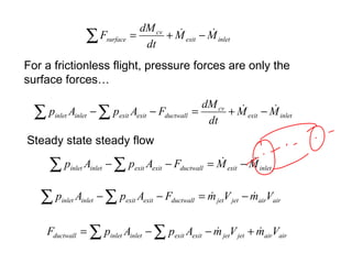
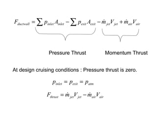
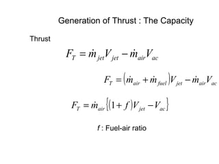


The document provides information about jet engine propulsion, including the major components and processes involved. It discusses the global momentum analysis and equations for jet engines. It also covers types of propulsion systems, classifications of jet engines, and the basic operation and components of jet engines such as the compressor, combustor, turbine, and nozzle. Key components and their functions are described, including how compressed air is mixed with fuel and ignited to produce thrust through exhaust exiting the nozzle.


