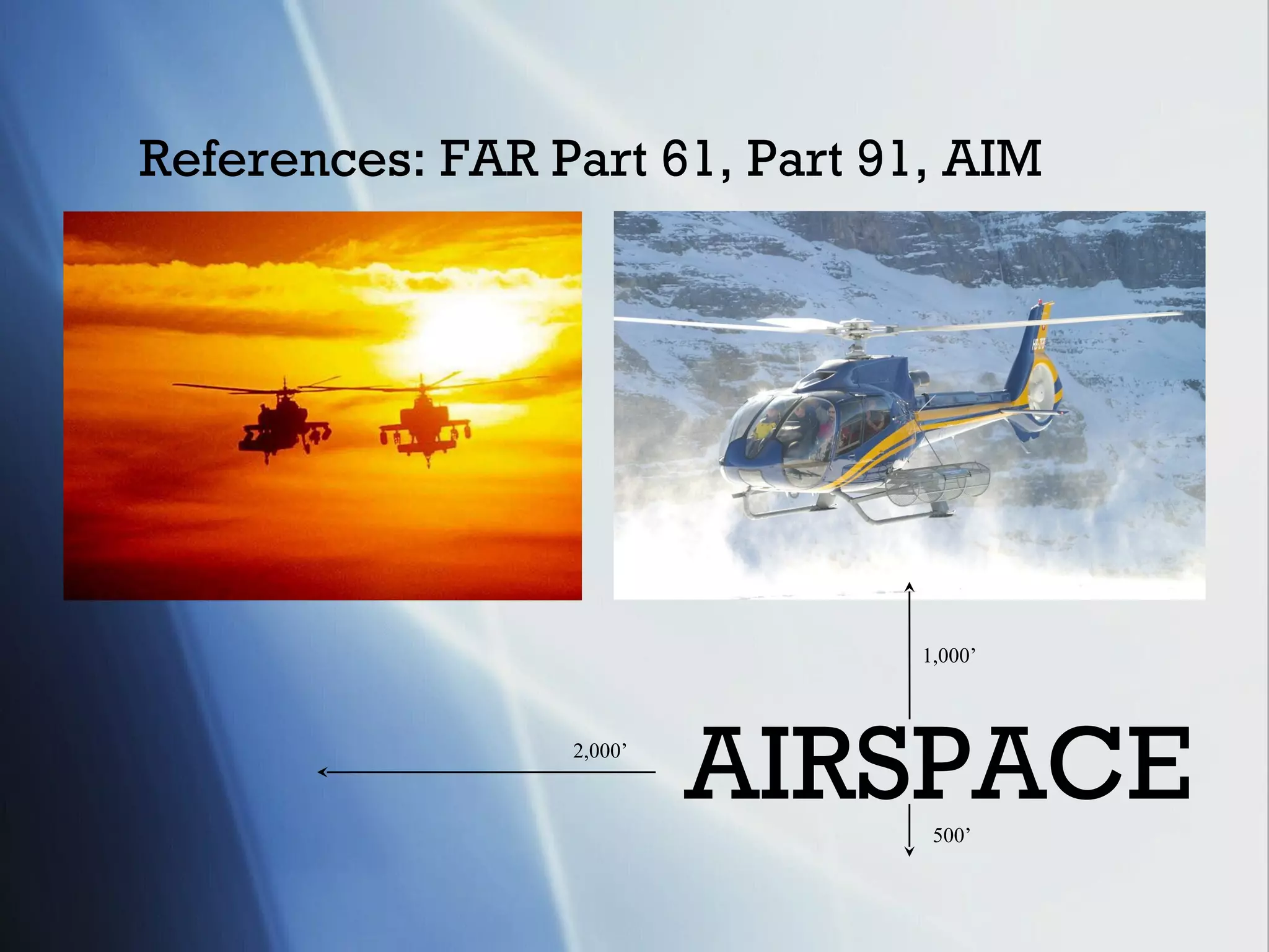
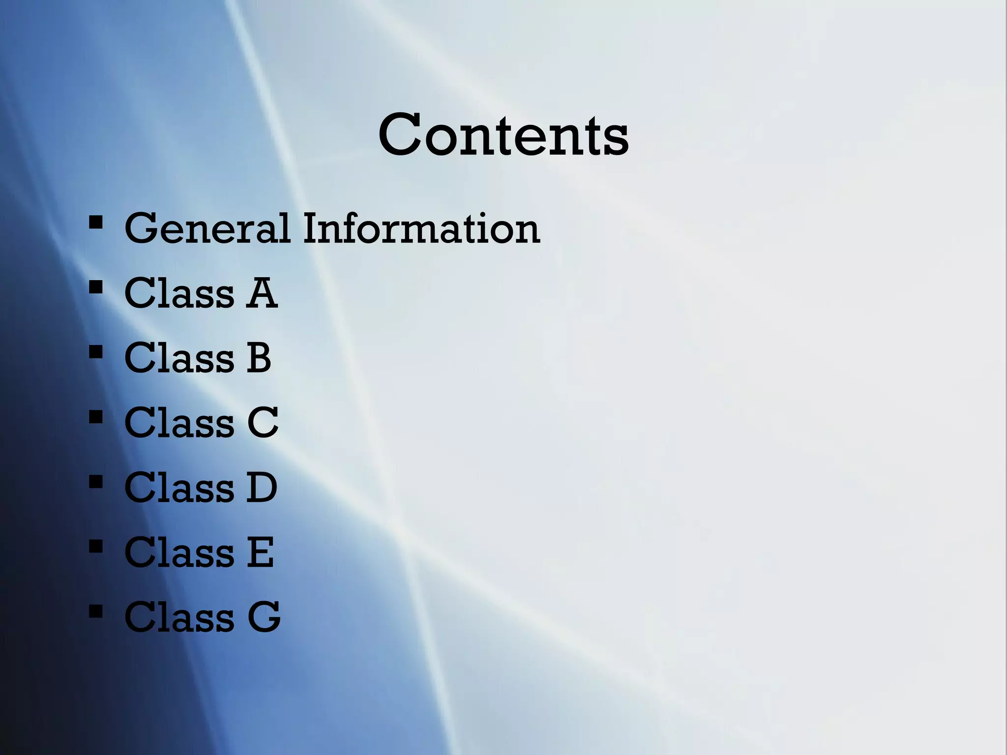
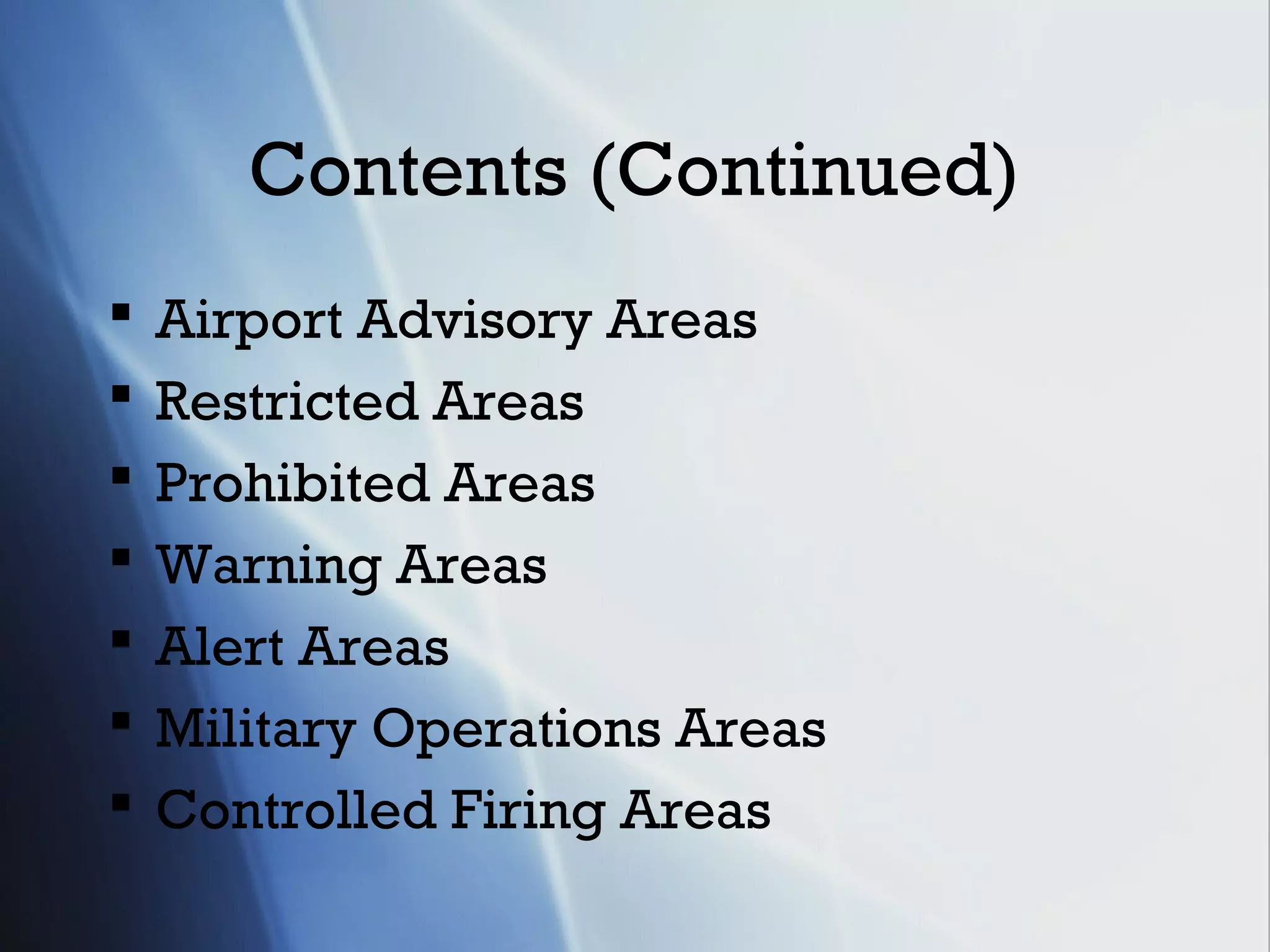
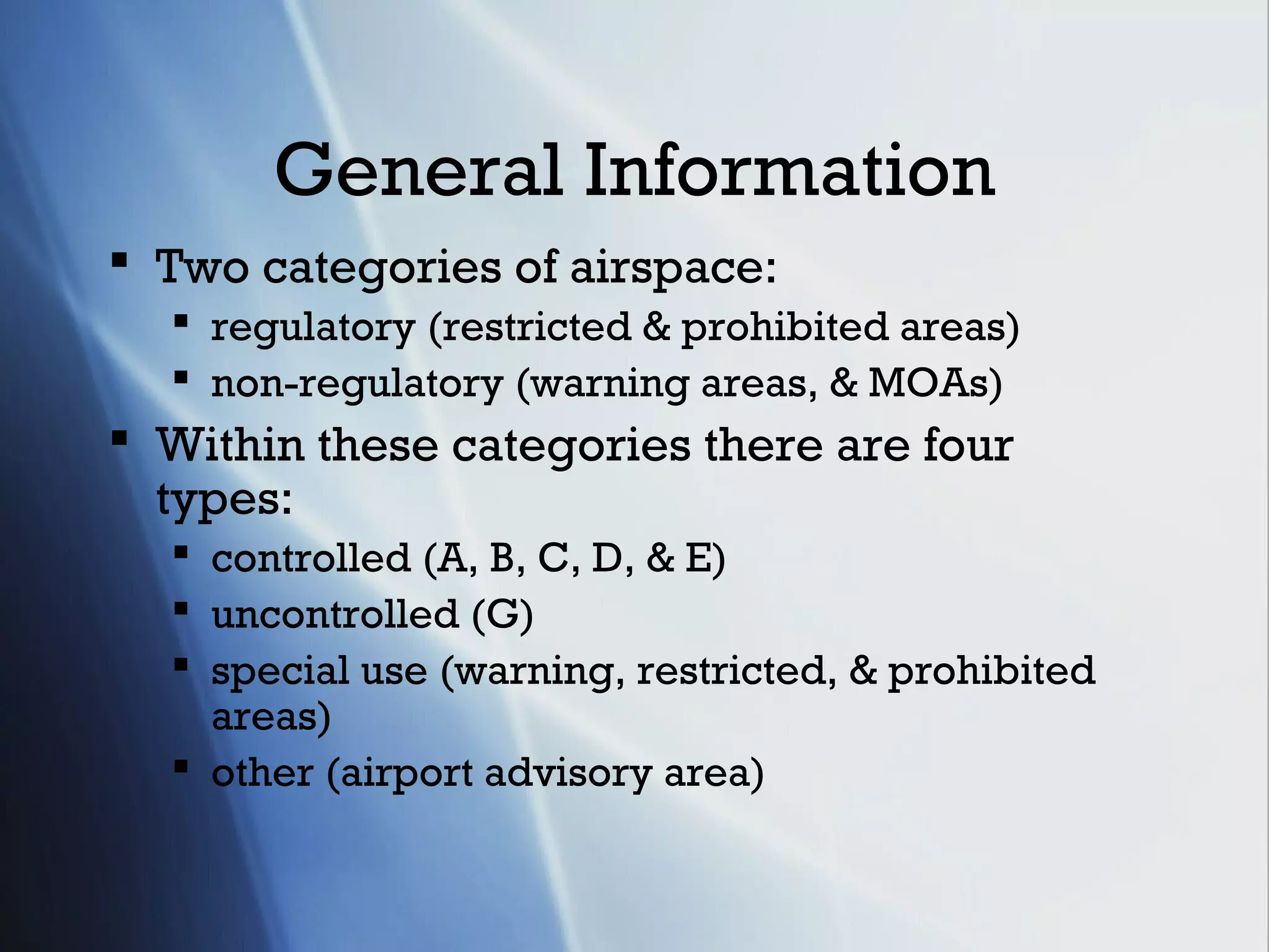
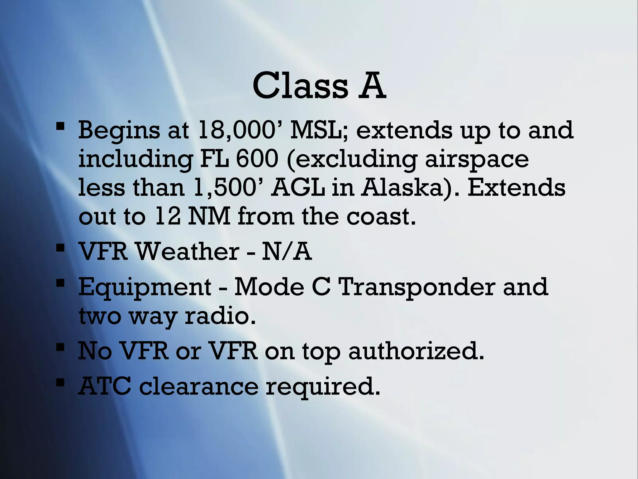
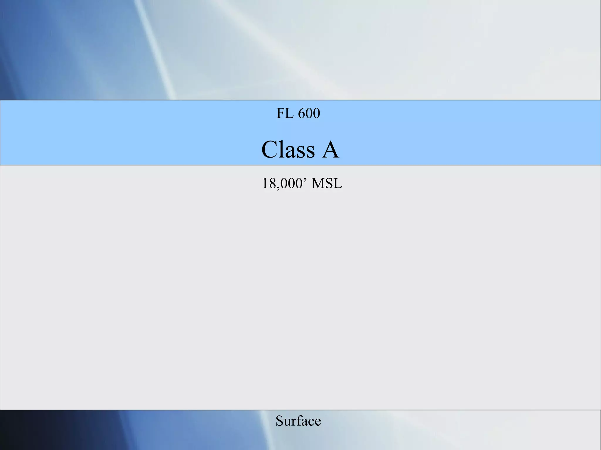
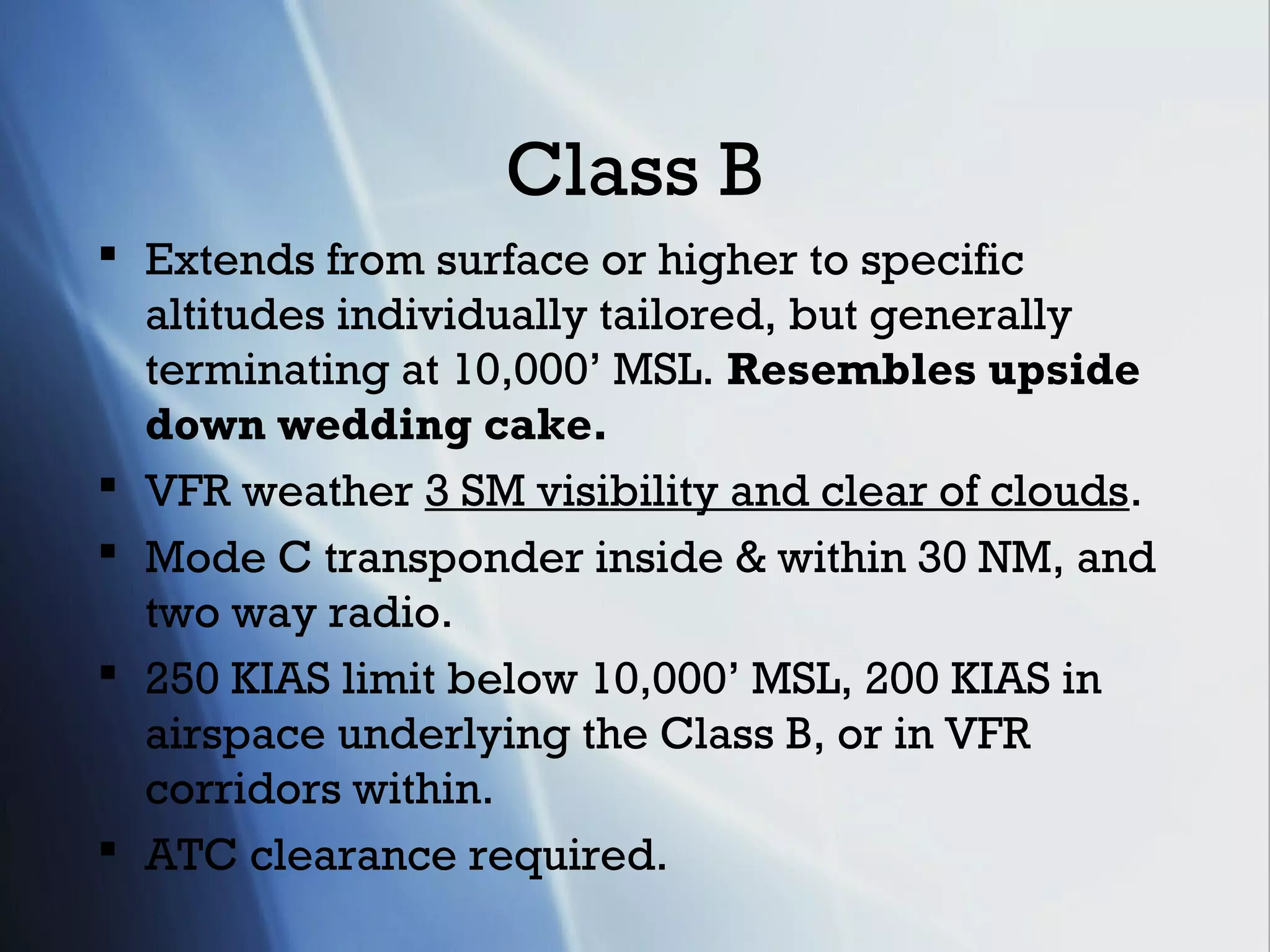
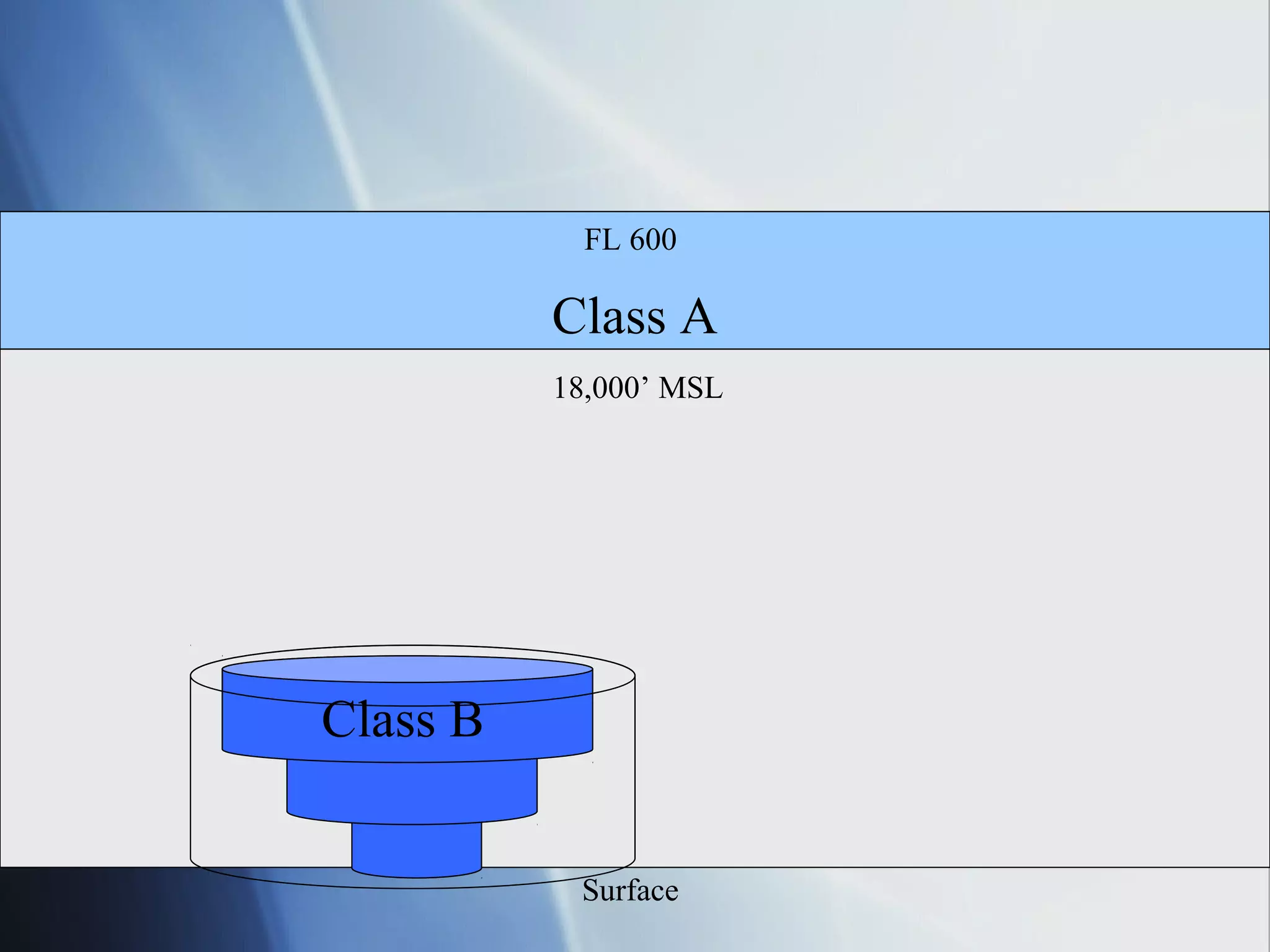
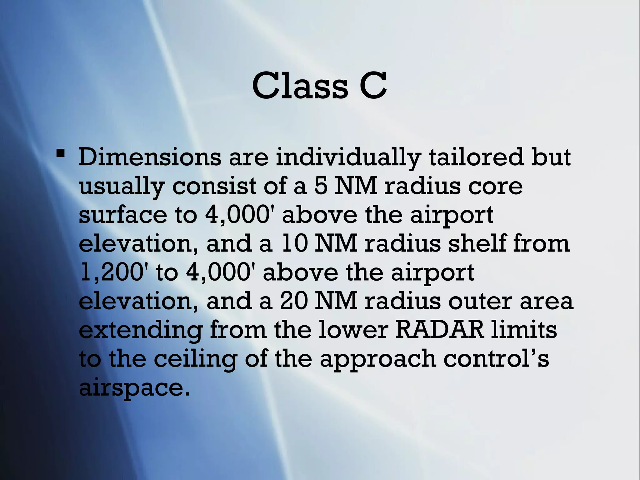
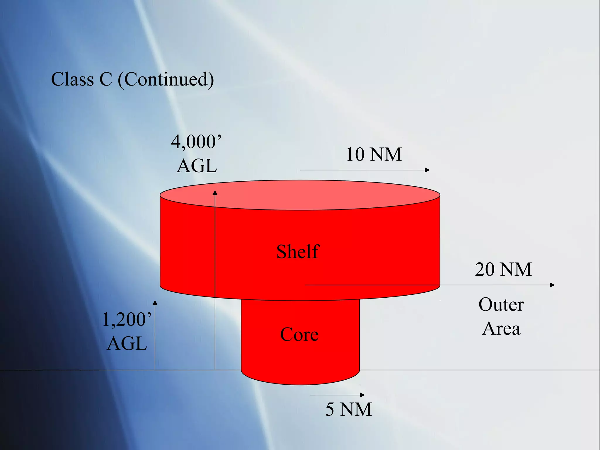
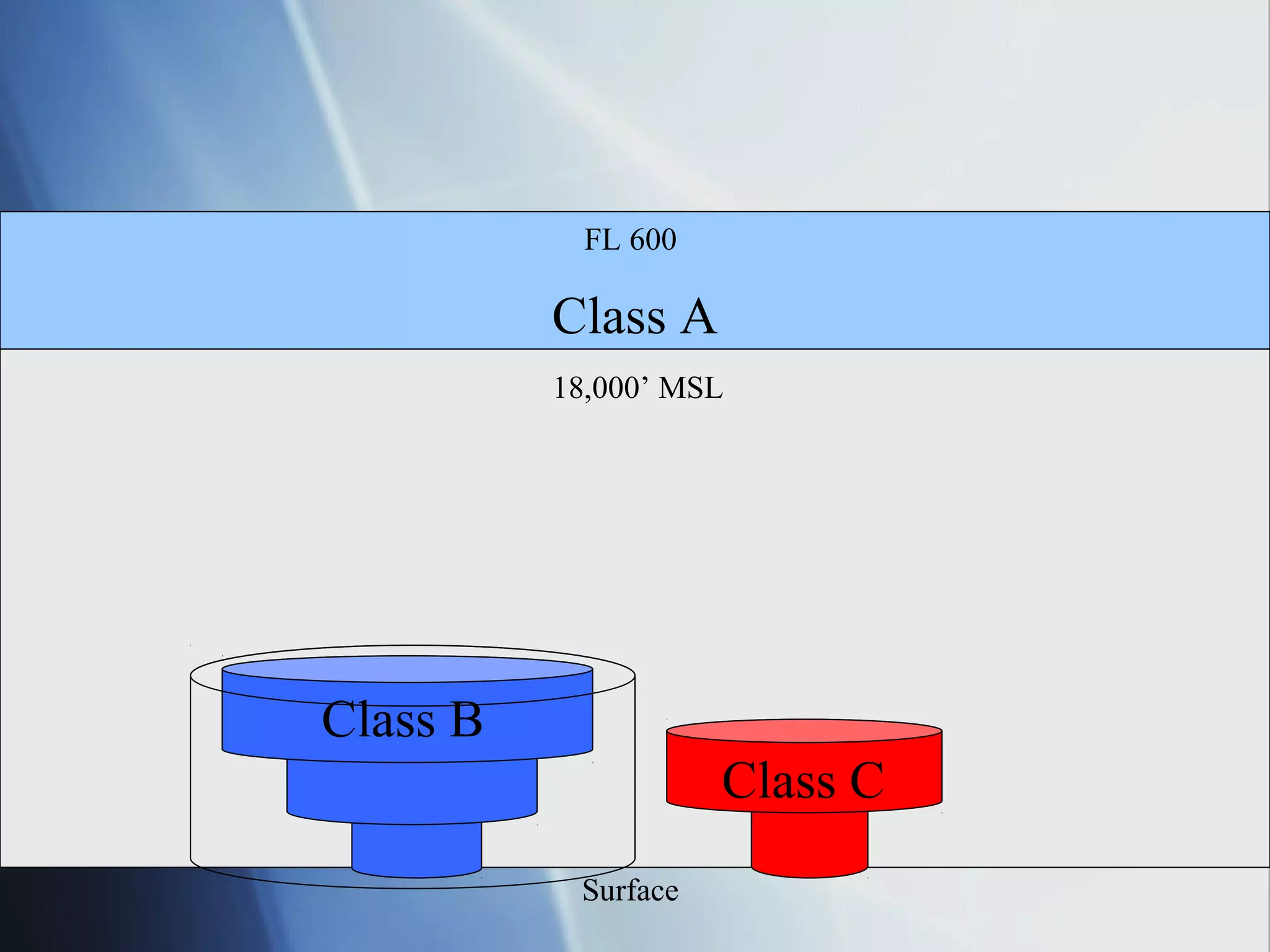
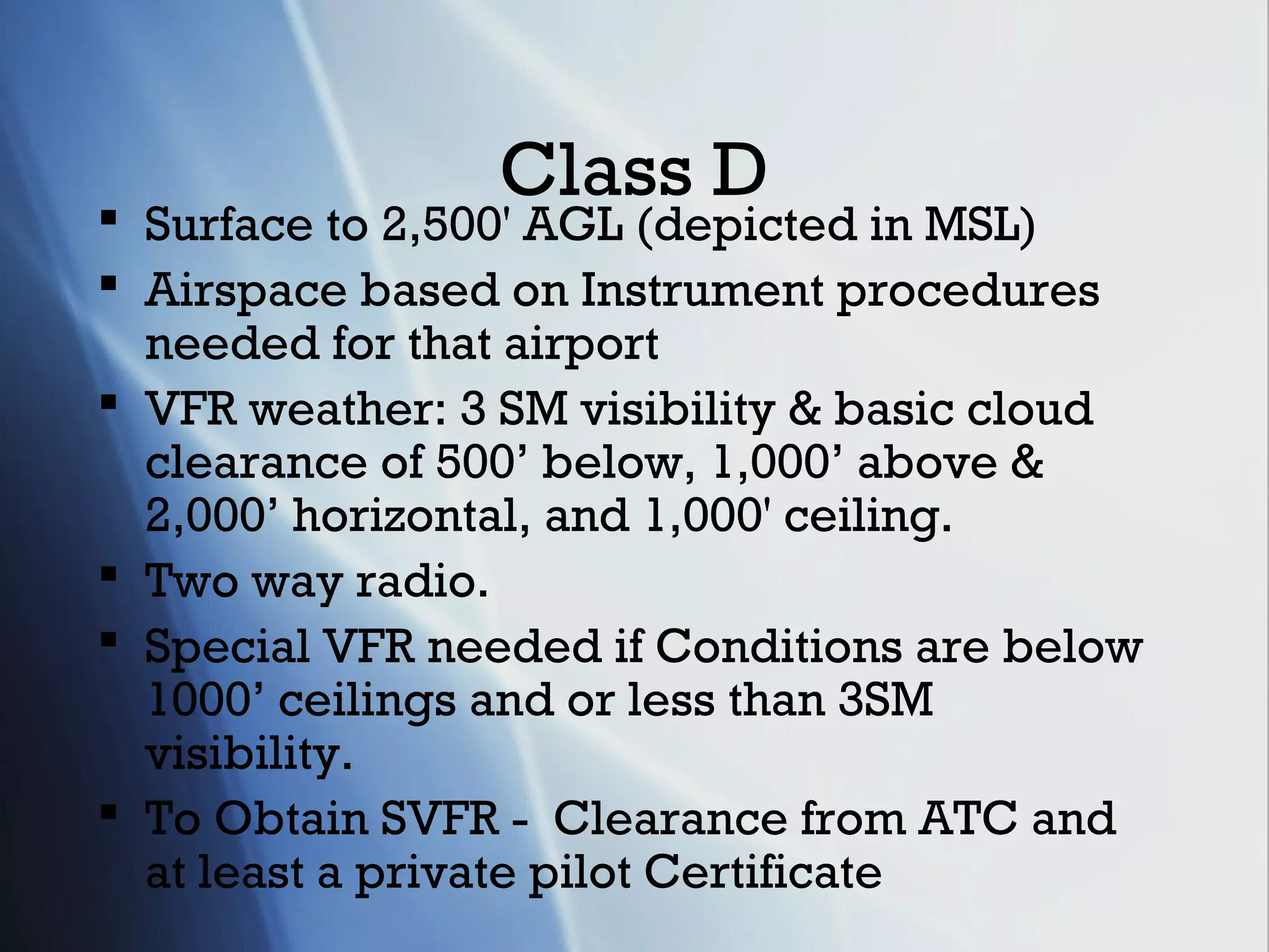
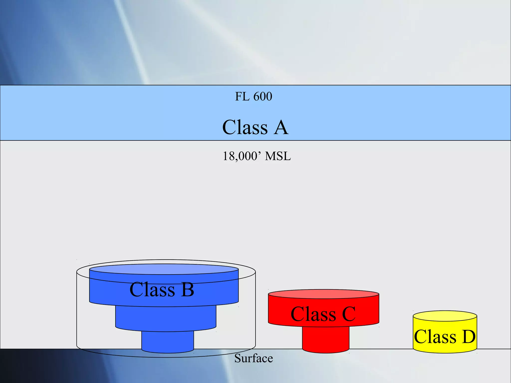
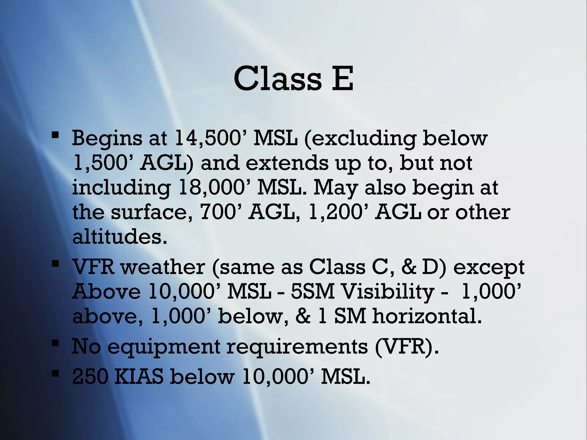
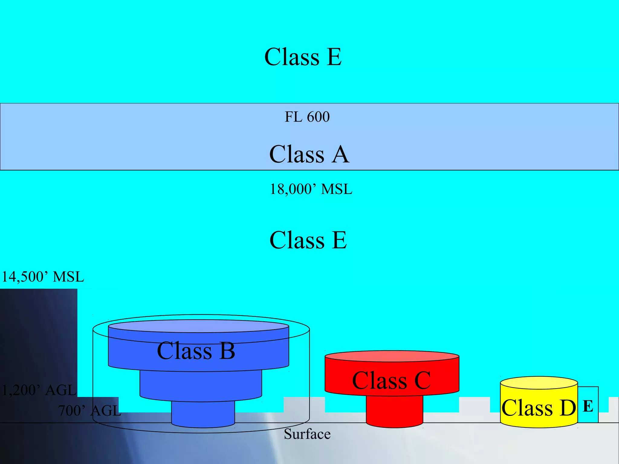
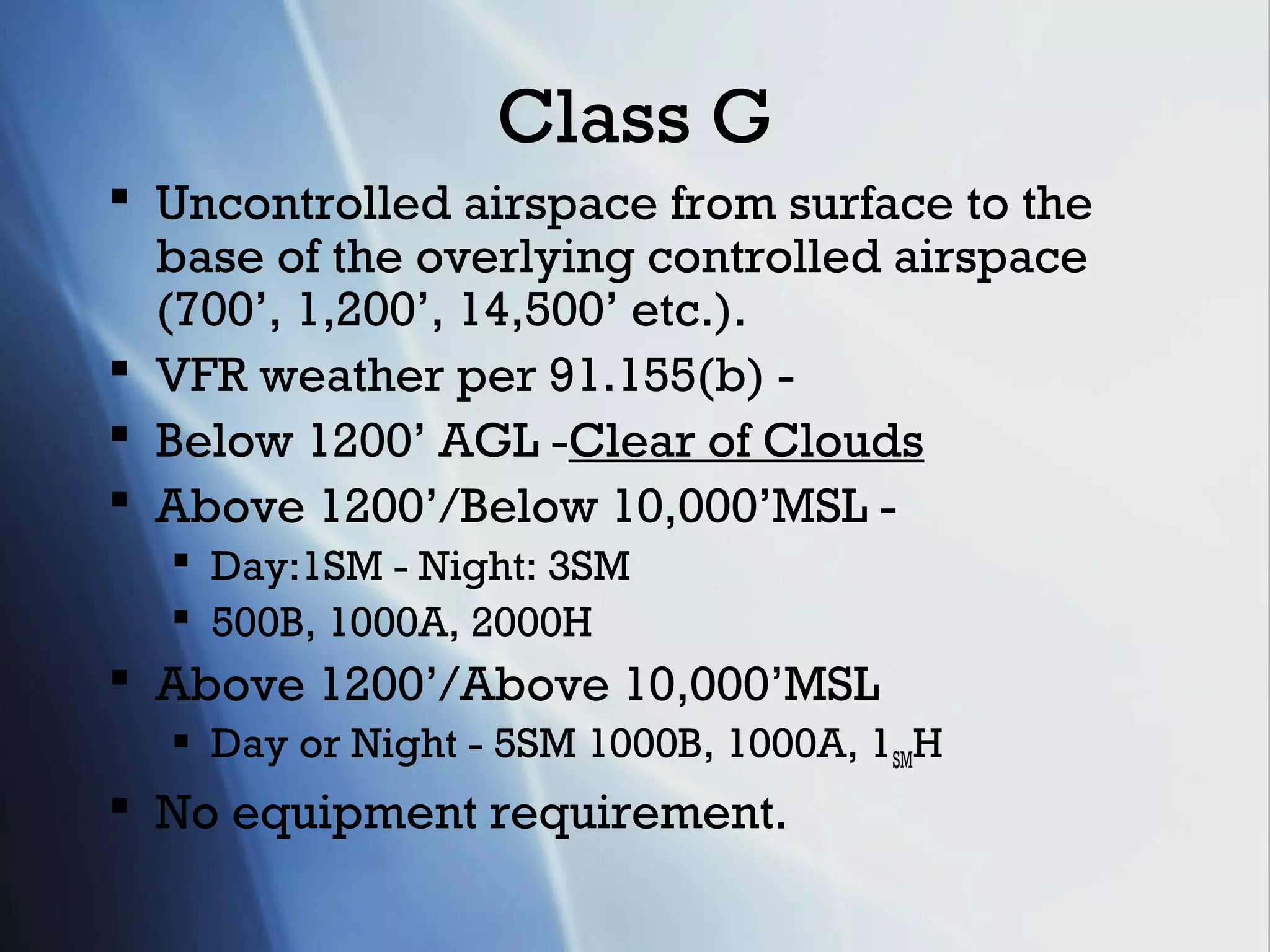
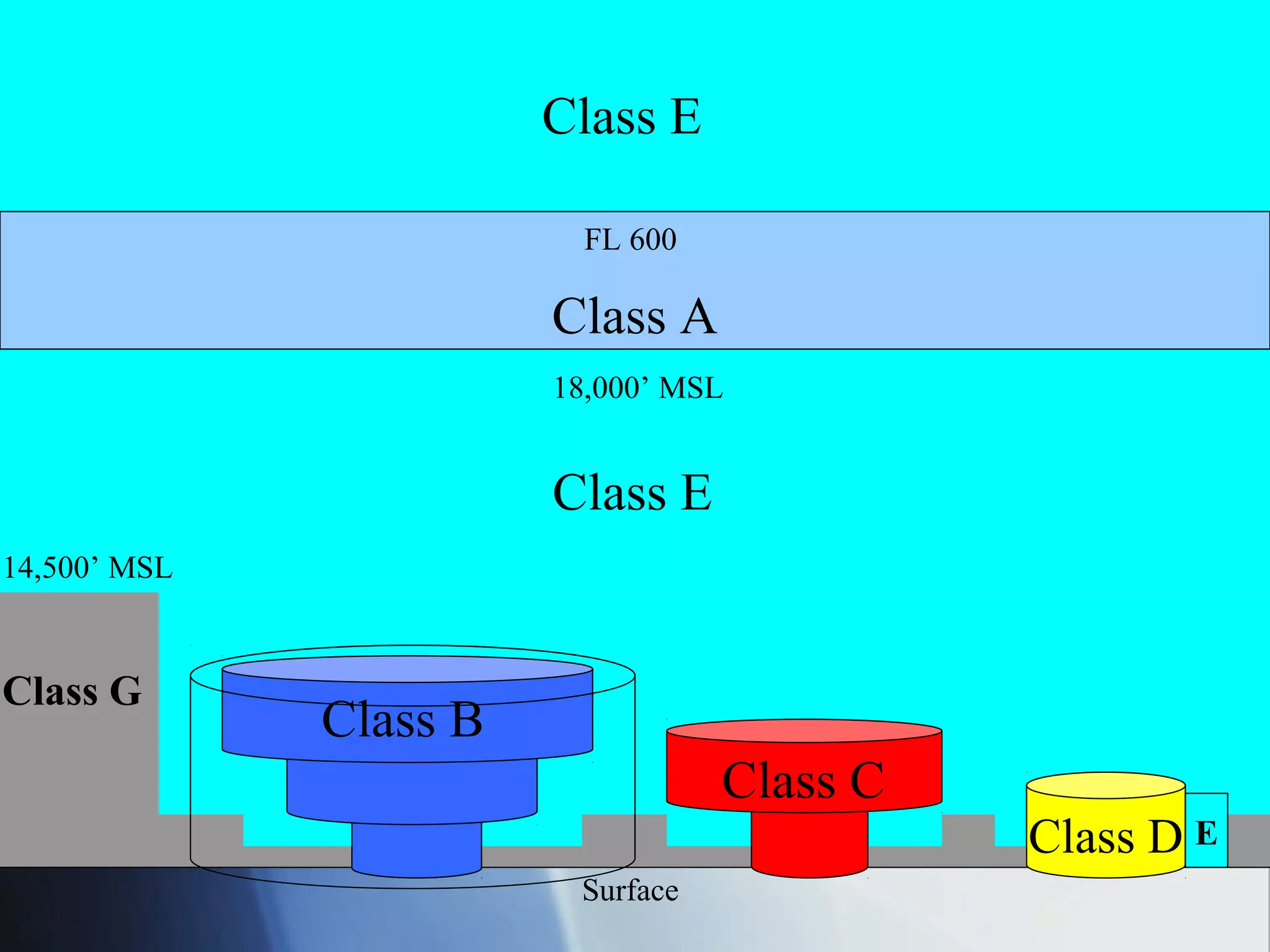
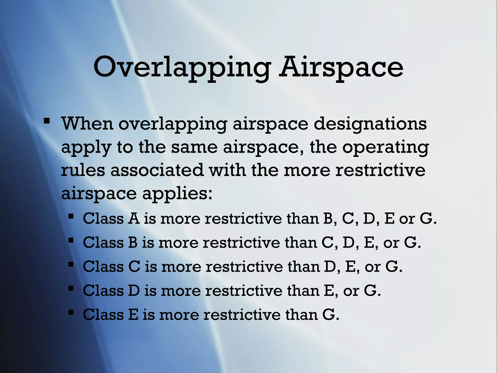
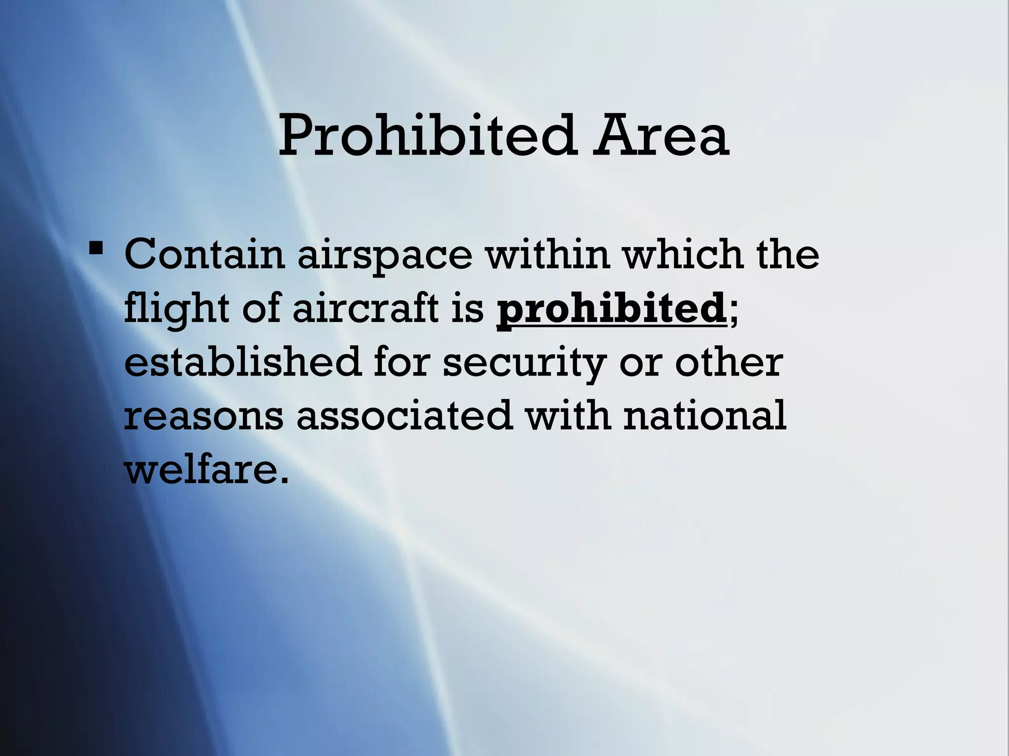
The document summarizes the different classes of airspace in the United States, including controlled airspace (Classes A, B, C, D, E), uncontrolled airspace (Class G), and special use airspace such as restricted areas, prohibited areas, warning areas, military operations areas, and controlled firing areas. It describes the operating rules, pilot certification and equipment requirements, dimensions and other characteristics of each class of airspace.
National Airspace System(NAS) Review
Class A airspace extends from 18,000 feet MSL to FL600. Pilots must be IFR certified and flying an IFR flight plan. Class B airspace surrounds large airports and requires a transponder and radio clearance for entry. Class C airspace surrounds medium airports and requires a transponder and radio contact for entry. Class D airspace surrounds small airports and requires only a radio for entry. Class E exists at various altitudes from the surface to 18,000 feet MSL and requires no special equipment. Class G is uncontrolled airspace that exists from the surface to 14,500 feet MSL. Special use airspace includes restricted areas,
Class G airspace has the fewest restrictions and is closest to the ground, while Class A airspace is the most restrictive and prohibits VFR flight. Each class has different pilot certification, equipment, and weather minimum requirements that become more stringent from Class G to Class A airspace. Special use airspaces also exist for security or military reasons and may impose additional limitations on aircraft. Knowledge of the national airspace system is essential for safe cross-country soaring flights.
Here you will find everything that you need to know about Aviation Charts right from their history, evolution and the type of charts that we use today.
Air traffic control (ATC) involves ground-based air traffic controllers directing aircraft both on the ground and in the air. The primary purposes of ATC are to prevent collisions, organize efficient air traffic flow, and provide pilots with information. Controllers operate air traffic control systems to expedite air traffic safely and prevent mid-air collisions. ATC has developed since the 1920s with the introduction of radio technology and navigation aids, and establishment of regulations and procedures. Key types of ATC services include area control, approach control, aerodrome control, flight information, and alerting services.
This document provides an overview of low visibility operations (LVO) including Category II, Category IIIA, and low visibility takeoffs. It defines key concepts such as decision height, runway visual range, operating minima, and requirements for aircraft, airfields, and flight crews to conduct these special operations. Category II allows for a manual landing at DH between 100-200 feet while Category IIIA requires an automatic landing system and has a DH under 100 feet or no DH with an RVR no less than 200 meters.
This document discusses various types of radar services used in air traffic control. It describes primary surveillance radar (PSR) which detects aircraft via reflected radio pulses, and secondary surveillance radar (SSR) which detects aircraft via transponder signals. SSR provides additional information like identification, altitude and speed. The objectives of radar services are improving airspace usage, reducing delays, and enhancing safety. Radar is used to provide area control services for enroute flights, approach control services within 50km of airports, and aerodrome control services at airports. Performance checks and identification procedures are discussed for maintaining radar separation standards between aircraft.
This document provides an overview of basic navigation concepts for pilots. It covers topics like reference lines on Earth, latitude and longitude, time zones, wind corrections, and magnetic variation. The objectives are to identify these concepts and perform calculations related to time, speed, distance and aircraft navigation. Various charts and examples are provided to demonstrate applications of these navigational techniques.
This document provides information on the aeronautical experience, flight time requirements, and currency requirements to obtain an instrument rating for airplanes. It also summarizes regulations regarding aircraft and personal documents required for IFR flight, as well as preflight planning considerations such as weather minimums, alternate airports, and fuel requirements. Additionally, it outlines standard instrument procedures such as IFR flight planning, approach types, and cruising altitudes.
The Instrument Landing System (ILS) uses radio beams to guide aircraft during low visibility approaches and landings. ILS consists of ground-based transmitters that provide both horizontal and vertical guidance to aircraft. The localizer transmits left and right signals to guide aircraft horizontally along the runway centerline, while the glide path transmits upper and lower signals to guide aircraft vertically along the ideal descent glidepath. Onboard antennas and indicators in the cockpit allow pilots to follow the ILS beams for precise approaches down to decision heights as low as 200 feet during low visibility conditions.
This document provides an overview of weight and balance concepts for aircraft. It defines key terms like empty weight, useful load, center of gravity, moment, and arm. It explains how weight and balance affects aircraft performance and safety. Maintaining the proper center of gravity is important for longitudinal stability and control. Being over or under weight limits can reduce performance and endurance or cause structural issues. The document also describes how to calculate weight and balance using information in the aircraft's Pilot Operating Handbook.
The document discusses factors that affect aircraft takeoff and landing performance at airfields, including:
- Runway length required for takeoff versus available length based on aircraft weight and design
- Impact of obstacles that must be cleared during takeoff
- Effects of high temperature and altitude on airfield performance due to lower air density
- Impact of wet runways, wind conditions, and maximum certified landing weight on performance.
The document discusses speeds that are important for takeoff performance of JAR 25 aircraft. It defines key speeds such as stall speed, minimum control speeds on the ground and in the air, engine failure speed, minimum unstick speed, lift-off speed, maximum tire speed, and maximum brake energy absorption speed. It also discusses operative speeds used for takeoff including decision speed (V1), rotation speed (VR), and takeoff safety speed (V2). Factors that can affect takeoff performance and speeds are also summarized such as flap setting, runway slope, wind, density altitude, aircraft systems, and runway contamination.
This document discusses factors that must be considered when planning an IFR flight, including origin and destination, weather, route, distance, speed, weight and balance, fuel, and alternates. It also describes the components of a flight plan such as the fuel plan, weight restrictions, navigation plan, air traffic services routing, and weather forecast. Finally, it provides details on various stages of flight like standard instrument departures, transitions, enroute navigation, standard terminal arrivals, instrument approach procedures, and ETOPS flights.
The document discusses air traffic control and services. It aims to prevent collisions between aircraft during flight and on the ground through separating aircraft laterally and longitudinally based on distance and time. It describes control areas like aerodromes and traffic zones. It also discusses flight level assignment, area navigation systems, routes and waypoints to guide aircraft along planned paths.
This document discusses various aspects of aerodrome data including:
- Types of aerodromes in India such as international, domestic, and military.
- Parameters of the Chennai aerodrome including its location, runway details, and elevation.
- Key components of aerodrome data shown on charts such as runways, taxiways, navigation aids, and obstacle restrictions.
- Characteristics of runways like dimensions, markings, visual aids, and factors that determine their length.
This document outlines the requirements for pilots to carry passengers, act as pilot-in-command under instrument flight rules or in reduced visibility, and maintain instrument currency and ratings. It discusses the use of flight simulators, flight training devices, and aviation training devices for completing instrument training and experience requirements. It also provides summaries of various briefing, inspection, and pre-flight requirements for instrument flight.
This document discusses the primary flight controls of aircraft:
1. The elevator controls pitch around the lateral axis using upward and downward deflection. Larger aircraft use hydraulic or electric systems.
2. The rudder controls yaw around the normal axis and is operated by rudder pedals, which also control steering while taxiing. Some aircraft with V-tails use linked ruddervator surfaces.
3. Ailerons control roll around the longitudinal axis and work differentially to bank the aircraft, sometimes assisted by differential rudder inputs to coordinate the turn. Some light aircraft use flaperons.
Este documento describe los procedimientos de coordinación entre diferentes dependencias que suministran servicios de control de tránsito aéreo. Explica los requisitos mínimos de coordinación entre control de área, aproximación y torre de control, así como los datos e información que deben intercambiarse. También cubre temas como puntos y condiciones de transferencia de control entre dependencias adyacentes.
TCAS was developed in response to mid-air collisions between aircraft. In the 1970s, an alternative airborne system called BCAS was proposed that used transponders to supplement radar information. This system was later renamed to TCAS. By the 1990s, Congress mandated that all commercial aircraft operating in the US must have TCAS installed. TCAS assists pilots in preventing collisions by interrogating other aircraft's transponders to determine their flight paths and identifies potential threats.
Este documento proporciona información sobre el formato y contenido del plan de vuelo IFR (Flight Plan). Explica cada una de las secciones del plan de vuelo, incluyendo información sobre el tipo de vuelo, aeronave, equipos, ruta, velocidad de crucero, aeropuertos de origen y destino, y otros detalles.
The document discusses aircraft performance certification and optimizing an aircraft's payload and range ability given physical and environmental limitations. It covers manufacturer's weight empty, operating empty weight, maximum zero fuel weight, maximum takeoff weight, and how payload and fuel affect an aircraft's range. Changing design aspects like maximum takeoff weight, zero fuel weight, and fuel capacity can impact the payload-range envelope.
Air Traffic Control (ATC) manages air traffic to maintain safe distances between aircraft, prioritize emergency aircraft, and provide safety alerts. ATC separates aircraft using different procedures depending on the phase of flight, such as arrival/departure towers keeping one aircraft on the runway at a time. Controllers monitor aircraft by radar and issue clearances to ensure required distances between Instrument Flight Rule aircraft, while providing advisory services to Visual Flight Rule aircraft. Emergencies have the highest priority and ATC assists them by clearing airspace and directing them to available runways and emergency services.
1. The document discusses emergency response procedures for dangerous goods incidents on aircraft. It outlines the information that must be provided to pilots regarding dangerous cargo and emergency procedures.
2. It describes the different classes of cargo compartments on aircraft and emergency equipment located on board. Checklists are provided for pilots and cabin crew to follow in case of a dangerous goods fire, spill, or leakage in the passenger cabin or cargo areas.
3. An emergency response chart is presented listing different drill codes corresponding to the risks of various dangerous goods and outlining spill and firefighting procedures for each.
The document discusses key aspects of ICAO's Annex 14, which provides standards and recommended practices (SARPs) for aerodrome design and operations. It outlines the objectives and methodology for understanding Annex 14 SARPs. It describes the development and amending process of SARPs and the contents and structure of Annex 14, including the aerodrome reference code system and different types of instrument approaches. It also summarizes important SARPs related to physical characteristics like obstacle limitation surfaces, runway characteristics, visual aids markings and lighting systems.
This document provides an overview of the Instrument Landing System (ILS). It discusses the history and development of the ILS from the 1920s onwards. Key components of the ILS are described, including the localizer which provides horizontal guidance, the glide slope which provides vertical guidance, and marker beacons which help pilots check their height and distance from the runway. The document also covers ILS categories, critical areas, maintenance, and future developments. In summary, the ILS is a critical radio navigation system that guides aircraft to the runway during low visibility conditions, and remains the most accurate system for approaches and landings despite being in use for over 60 years.
Presentacion Los Servicios De Transito AereoFLAP152
El documento describe los objetivos, funciones y servicios de los servicios de tránsito aéreo, incluyendo el control de tránsito aéreo, información de vuelo y alerta. Explica la clasificación del espacio aéreo, las reglas para vuelos visuales y por instrumentos, y los procedimientos para cambiar la configuración del altímetro.
This document provides an overview and summary of the Level 2 Airside Driver Training course at Launceston Airport. The 3-sentence summary is:
The training course covers the rules, regulations, and safety policies for driving airside at Launceston Airport, including definitions of key areas, vehicle authorities required, speed limits, safety around aircraft, spill and accident reporting procedures, and markings like taxiway and parking lines. Completing the course provides drivers with the knowledge to safely operate vehicles airside while following all applicable rules to protect aircraft operations, infrastructure, and all personnel in the airside environment.
This document provides specifications for bag components of three bag sizes - Mini, Medium, and Large. It specifies dimensions and tolerances for the bag shell, bottom board, turntop, side seam, patch paper, handles, bag graphics, and general dimensions. Dimensional tolerances are specified as ±1/8 inch unless otherwise noted. The document includes diagrams and notes intended to ensure dimensional consistency and quality for bag production.
The document discusses the importance of aviation to the US economy and national airspace system. It notes that aviation supports over 997,000 jobs and $445 billion in economic activity annually. It also highlights some of NASA's aeronautics research, including estimated cost savings from new technologies, safety research initiatives, and support for alternative fuel development. The budget provides funding to enhance contributions to NextGen and areas like unmanned aircraft integration and environmentally responsible aviation.
This document summarizes various publications and resources for IFR flight planning and procedures. It discusses IFR flight plans, clearances, departure procedures, en route charts, and more. Key points include requirements to file an IFR flight plan, elements of IFR clearances like altitude assignments and holding instructions, and preplanned departure procedures like SIDs and ODPs.
Climb via, descend via, and speed adjustment phraseology & proceduresUPSAirlines
This document from the FAA discusses new phraseology and procedures for vertical navigation clearances called "climb via" and "descend via". It defines climb/descend via as authorizing pilots to navigate vertically and laterally on published Standard Instrument Departures or Standard Terminal Arrival Routes, complying with all restrictions. It provides guidance to air traffic controllers on implementing these procedures, including assigning interim altitudes, resuming procedures after vectors, and coordinating with published restrictions. The goal is to provide more efficient clearance of aircraft as they transition between different altitudes and routes.
This document provides an overview of several key regulations in 14 CFR Part 91 that pilots must follow, including regulations regarding aircraft airworthiness (91.7), preflight actions (91.103), use of safety belts (91.107), minimum safe altitudes (91.119), transponder requirements (91.215), and more. It highlights some of the main requirements and considerations for each regulation discussed.
Class C airspace consists of controlled airspace around larger airports with an airport traffic control tower. It has two rings around the primary airport - an inner ring from 5 nm radius of the airport surface to 4,000 feet AGL, and an outer ring from 5-10 nm radius from 1,200 to 4,000 feet AGL. There is also an undefined "outer area" that extends 20 nm laterally from the airport and from the lower limits of radar coverage to the approach control's delegated airspace ceiling. To operate within Class C airspace requires having a Mode C transponder, being in two-way communication with ATC, but no specific pilot certification.
This document discusses procedures for instrument flight rules (IFR) communications and operations, including IFR departures, arrivals, air traffic flow, and holding procedures. It provides an overview of key concepts for pilots navigating under IFR and interacting with air traffic control.
This document provides guidance to air traffic controllers on procedures for visual flight rules (VFR) operations and visual approaches. It discusses when visual separation can be applied between aircraft, procedures for clearing aircraft to maintain VFR conditions or VFR-on-top in controlled airspace, and requirements for conducting simultaneous visual approaches to parallel, intersecting, or converging runways. Controllers must ensure standard separation minima are maintained unless the specific conditions for visual separation or visual approaches are met.
This document discusses airborne laser scanning (ALS) and its applications. It begins by defining ALS and its history. It then describes the key components of a typical ALS system, including a laser, scanner, GPS, IMU, and control units. It discusses how ALS measures distance and collects point cloud data. Application examples are given, such as generating digital terrain models and surface models over large areas. The document also includes a case study on using ALS and high-resolution satellite data to study geomorphic features in parts of the Elbe River valley in Germany.
The National Airspace System (NAS) is overseen by the Federal Aviation Administration (FAA) and includes the Air Traffic Control (ATC) system. The ATC system uses technologies like radar, satellite navigation, and air/ground communications to direct air traffic safely and efficiently. Within the FAA, the Air Traffic Organization (ATO) manages air traffic control facilities across various regions. These
Airspace is divided into different classes that regulate aircraft operations. The main classes are:
Class A airspace requires all flights to operate under instrument flight rules. Class B and C airspaces surround major airports and require two-way communication and ATC clearance. Class D airspace surrounds smaller airports and also requires communication with ATC. Special use airspaces include prohibited areas, restricted areas, military operation areas, and alert areas that have unique rules and restrictions. Temporary flight restrictions can also be established through notices to restrict certain airspace temporarily.
Pilot error can occur in three ways: perceptual errors from failing to notice information, procedural errors like entering incorrect data, and decisional errors such as continuing flight into unsafe conditions. Good aeronautical decision making involves continuously perceiving information, processing it methodically using tools like CARE, then performing the appropriate action or inaction. It is important to evaluate decisions to catch errors and improve decision making.
09-Runway Configuration ( Highway and Airport Engineering Dr. Sherif El-Badawy )Hossam Shafiq I
The document discusses various runway configurations including single, parallel, staggered parallel, intersecting, and open-V runways. It also describes different types of taxiways like entrance, exit, parallel, bypass, and connecting taxiways that make up the ground movement network at an airport. Flight rules depend on weather conditions, with visual flight rules applied during good visibility and instrument flight rules in low visibility conditions.
EASA Part 66 Module 15.5 : Combustion Chambersoulstalker
The combustion section is part of an engine where fuel is burned, increasing pressure, volume, and temperature to convert the kinetic energy of high velocity air into rotational energy of the turbine. It contains a combustion chamber where fuel mixes with compressed air and burns, and may have an annular design to maximize combustion efficiency and minimize emissions.
Este documento resume las normas y reglamentos internacionales para la aviación civil contenidos en el Anexo 2 del Convenio sobre Aviación Civil Internacional. Incluye definiciones clave, reglas generales para la protección de personas y propiedad, prevención de colisiones, y requisitos para planes de vuelo. También cubre la aplicación territorial de los reglamentos, responsabilidades de los pilotos, y uso de sustancias psicoactivas.
EASA PART 66 Module 15.10 : Lubrication Systemssoulstalker
The lubrication system supplies pressurized oil to bearings using various pumps and filters to lubricate and cool components. It consists of an oil tank, pumps that pressurize the oil, filters that clean the oil of debris, oil coolers that cool the oil and fuel, and magnetic detectors and valves that monitor the oil system and maintain pressure. The main types of bearings used are spray jet, splash, metered, film, and squeeze film bearings that are lubricated via direct oil spraying, splashing, metering based on engine speed, oil films, or minimizing dynamic loads respectively.
This document defines and describes the various classes of airspace in the United States, including Class A, B, C, D, E, and G. It details the characteristics, requirements, and restrictions for pilots operating in each class of airspace. The classes range from the most restrictive Class A airspace above 18,000 feet MSL to the unclassified Class G airspace at lower altitudes. Special use airspaces like Restricted Areas are also outlined.
FLIGHT INSPECTION of CNS FACILITIES [Compatibility Mode].pdfssuser1edd921
The document discusses flight inspection procedures for navigation aids. It describes the periodic ground and flight tests required by ICAO for radio navigation aids to ensure they are maintained within tolerance limits. The key types of inspections are commissioning, routine, special and site evaluation inspections. Flight inspection procedures are then outlined for localizers and glide paths, checking parameters like coverage, course width, clearance, structure and monitor alarms to ensure compliance with ICAO standards.
The document contains a 15 multiple choice question test about visual flight rules (VFR), instrument flight rules (IFR), air traffic control procedures, aerodrome operations, and aviation definitions. It covers topics like VFR weather minima, right of way rules, position reporting under IFR, radio communications procedures during interceptions, meaning of aerodrome light signals, and definitions of aviation terms. The questions test knowledge of standard procedures and regulations for visual and instrument flight operations.
This document discusses various aspects of air traffic management at aerodromes, including the functions of aerodromes, services provided like air traffic control and flight information, runway inspections, responsibilities of air traffic control towers, flight priorities, aircraft wake turbulence classifications, lighting signals for aircraft on the ground, criteria for suspending VFR operations, factors in runway selection, obstacles and limitations, instrument flight rules within controlled areas, facilities available in towers, and definitions of key terms.
This document provides guidance to air traffic controllers on procedures for vectoring aircraft to the final approach course and issuing clearances during instrument approaches using radar. It specifies requirements for intercepting the final approach course at least 2 miles outside the approach gate unless certain conditions are met. It also provides guidance on issuing approach clearances, instructions on the approach frequency to contact, and examples of clearances.
This document provides definitions and procedures for visual approaches, contact approaches, and circling to land from an instrument approach. It defines a visual approach as approaching visually and clearing clouds to land at an airport. A contact approach allows proceeding visually to the destination airport when clear of clouds with at least 1 mile visibility. Circling to land brings an aircraft into position to land on a runway not aligned with the instrument approach. It provides circling area dimensions and procedures to maintain visual contact with the runway environment while circling to land.
This document provides procedures and rules for aircraft conducting weapons training at the Koon-ni Weapons Range. It outlines check-in procedures with the Range Control Officer (RCO) when entering the range airspace and protocols for the range patterns, minimum altitudes, abort criteria, radio calls, and ordnance safety. Specific rules address issues like chaff/flare expenditure, fouls, communications, and operations within the Special Use Airspace (SUA) of the Koon-ni Range Complex while conducting concurrent operations with other aircraft.
This document provides information for pilots flying in and out of Krugersdorp Airfield (FAKR) in South Africa, including:
- FAKR has a short gravel runway requiring precision to land, with risks of turbulence, wind shear, and crosswinds.
- Standard traffic patterns cannot be followed due to nearby controlled airspace. Joining procedures involve overhead entries from specific directions and altitudes while monitoring the radio frequency.
- Pilots must maintain situational awareness of other aircraft and obstacles on the airfield, follow radio procedures, and use good judgement when operating at the busy but unmanned field.
This document provides an overview of air traffic control (ATC) including:
1. It introduces ATC and its primary purposes of separating aircraft to prevent collisions, organizing traffic flow, and providing pilot support.
2. It summarizes key ATC concepts like ICAO, airspace classifications from A-G, controlled and uncontrolled airspace, and services like aerodrome/tower, area, and approach control.
3. It concludes that air traffic controllers play a vital role in safety by preventing collisions and following standardized rules and classifications to efficiently guide aircraft through the airspace.
Air traffic controllers apply separation rules to keep aircraft a minimum distance apart to reduce collision risks. Separation depends on factors like aircraft size, flight rules, and airspace class. In controlled airspace, controllers use radar, procedural, lateral, and longitudinal separation to ensure aircraft distances meet minimum standards. A conflict occurs when these separation minima are violated, threatening aircraft safety. Controllers aim to prevent conflicts through continuous monitoring and resolution of aircraft positions.
This document provides information on various topics related to aviation radio communication including phonetic alphabet, procedures for test transmissions and emergency situations, aeronautical station call signs, Q codes, location indicators, and proper transmitting techniques. It defines key terms, lists emergency codes and information to include in emergency messages. It also describes the different categories of aeronautical communications services and important annexes related to telecommunications.
There are differences between FAA and ICAO procedures regarding radio communications, VOR checks, transponder requirements, oxygen requirements, IFR minimum equipment, wake turbulence separation criteria, high and low altitude airspace fixes, textual descriptions of SIDs, holding pattern timing, holding speeds, two and three fix holding patterns, setting QNH on altimeters, and loss of radio communications procedures. Adhering strictly to ICAO phraseology and procedures is important for safety when flying internationally. National regulations may vary slightly from ICAO standards in some countries.
This document outlines key differences in phraseology used in air traffic control communications between the International Civil Aviation Organization (ICAO) and the United States Federal Aviation Administration (FAA). It discusses differences in terminology for air traffic control units, procedures for clearances, wake turbulence separation, use of headings versus tracks, procedures following loss of radio communication, holding patterns, and approach procedures. The document is intended to help pilots learn and understand differences that could impact safety and procedures when flying internationally.
Several recent accidents involving controlled flight into terrain (CFIT) in visual conditions at night highlight the risks of nighttime visual flight in remote areas. Proper preflight planning and terrain familiarization are critical to avoid CFIT, as darkness can make visual avoidance of terrain nearly impossible. When receiving radar services, pilots should not rely on air traffic controllers to warn of terrain hazards and should advise ATC if unsure of ability to see and avoid terrain. Following instrument flight rules altitude minimums and using technology like terrain awareness systems can help improve safety for nighttime visual flights.
This document provides an introduction and overview of drones. It defines drones as unmanned aircraft controlled remotely and outlines their various uses from military to commercial applications. The document categorizes drones based on size and weight and describes different types including single-rotor, multi-rotor, fixed-wing, and hybrid designs. It also discusses drone regulations and airspace classifications in Malaysia and the process for obtaining a permit to operate drones commercially or for aerial work. Finally, it outlines the certification process for becoming a licensed drone pilot in Malaysia through vocational training programs.
The Instrument Landing System (ILS) provides precision guidance to aircraft during instrument approaches and landings. It uses radio signals from an antenna array installed at the end of runways to provide lateral and vertical guidance. The ILS allows aircraft to land safely during low visibility conditions. It consists of localizer and glide slope components that guide the aircraft to the runway centerline and a 3 degree glide path for landing. Marker beacons also help pilots locate distances from the runway threshold. The ILS enables categories of instrument approaches with minimum visibility and decision height requirements.
This document defines key distances related to aircraft takeoff and landing performance. It discusses:
- Screen height definitions for different aircraft types
- Definitions for runway, stopway, and clearway areas
- Declared distances including TORA, TODA, ASDA, and LDA that define available field lengths
- Required distances including TORR, TODR, and ASDR that must be met for safe takeoff and landing
- How to determine a balanced field length takeoff where TODR and ASDR are equal versus an unbalanced takeoff that takes advantage of a stopway or clearway.
This document provides information on geometric design considerations for airport runways, taxiways, and terminals. It discusses factors that influence runway orientation such as wind conditions and aircraft performance. It also describes guidelines for determining basic runway length based on elevation, temperature, and aircraft characteristics. Additional topics covered include runway configuration, geometry standards for length, width, gradients and sight distances, taxiway design standards, and concepts for terminal area layout and space requirements.
This document discusses various aspects of airport operations and air traffic control. It covers topics such as:
- How airspace is divided and types of airspace (controlled vs uncontrolled)
- Components of the air traffic control system like radar, flight strips, and navigational aids
- Air traffic control procedures at airports including approach, aerodrome, and ground controllers
- Runway configurations and factors that influence runway capacity like weather, traffic mix, and separations
- Procedures to optimize runway usage and reduce occupancy times through stacks, SIDs, STARs, and RETs.
Jayam College of Engineering and Technology (JCET) provides world-class engineering education and fosters research and entrepreneurship. Located on 80 acres near Hogenakkal Falls, it has 2500 students and 4000+ alumni. JCET offers UG and PG programs in engineering and business and has strong industry partnerships that help students gain work experience and high placement rates. It aims to develop leaders through quality education and a focus on research.
This document provides information about a subject code and unit taught by two lecturers, Mrs. A. Sangari and Mrs. P. T. Subasini, in the Electrical and Electronics Engineering department. The subject and unit are about induction motors and specifically discusses the concept of slip in induction motors.
The document traces the history of aircraft development from early concepts of human flight using flapping wings, to the first hot air balloons and gliders, to advancements such as the wind tunnel, ailerons and the internal combustion engine which enabled the first powered flights. Key contributors included Leonardo Da Vinci, the Montgolfier Brothers, Sir George Cayley, the Wright Brothers and engineers who developed jet engines. The document also outlines instruments used to measure aircraft parameters and types of aircraft developed through World War 1 and beyond.
The document discusses engineering graphics and freehand sketching. It covers curves used in engineering like conics, cycloids, and involutes. It also discusses representing 3D objects through multiple views and developing visualization skills through freehand sketching. The document then provides step-by-step instructions on orthographic projections using first angle projection. It demonstrates drawing front, side, and top views from pictorial presentations. Finally, it outlines the general procedure for freehand sketching orthographic views from an isometric pictorial view.
The document provides information about a class on DC motors taught by Mrs. A. Sangari and Mrs. P.T. Subasini. It lists the subject code as 131307 for the second year Electrical and Electronics Engineering students. The class covers the principles of operation, back emf and torque equations, characteristics of series, shunt, and compound DC motors. It also discusses starting methods and speed control of series and shunt DC motors.
This document provides details about the subject Electrical Machines taught by Mrs. A. Sangari and Mrs. P.T. Subasini. The subject code is 131307 and it covers DC generators in the first unit, including their construction details, the emf equation, methods of excitation for self and separately excited generators, and the characteristics and parallel operation of series, shunt, and compound generators.
As a helicopter develops lift during takeoff and flight, the blade tips rise above straight-out position and assume a coned shape. This coning occurs due to the combined effects of centrifugal force from blade rotation, which adds rigidity, and developing lift from the collective. Some coning is normal, but excessive coning can cause problems like decreased lifting area and blade stress due to factors like low RPM, high gross weight, turbulence, or high-G maneuvers reducing centrifugal force or requiring more lift.
Bernoulli's principle states that within a confined system, total energy remains constant, so if the velocity of a fluid increases, the pressure decreases. When air flows over an airfoil, its velocity increases and pressure decreases above the airfoil compared to below it, resulting in higher pressure below pushing the airfoil up. Most but not all of the lift is produced by this differential pressure - the rest is produced by Newton's third law of motion, as the air deflecting downward exerts an equal and opposite force lifting the airfoil upward.
This document discusses three basic laws of aerodynamics: Newton's Laws of Motion. It explains the Law of Inertia which states that an object at rest will remain at rest and an object in motion will remain in motion unless acted on by an outside force. It describes the Law of Acceleration which says that force is directly proportional to mass and change in velocity. It also outlines Newton's Third Law of equal and opposite reaction, giving the example of torque effect and recoil from a gun.
Autorotation is the process by which a helicopter can descend and land without engine power by using the airflow coming up from the ground or air during descent to turn the rotor blades and maintain control. During autorotation, the helicopter trades altitude for the energy required to spin the rotor blades at a speed that provides enough lift to control the aircraft. The pilot lowers the collective to reduce blade drag and tilt the total aerodynamic force vector forward to maintain rotor RPM as the helicopter descends.
This document discusses airfoil and rotor blade terminology. It defines symmetrical and nonsymmetrical airfoils and their characteristics. It also defines the angles of incidence, attack, and describes how collective and cyclic feathering changes these angles to control the helicopter. Flapping, lead, and lag are also summarized as important motions of the rotor blades that help control the aircraft.
This NASA document provides information about an educator's guide on aeronautics with activities in science, math, and technology. The guide and other NASA education products can be accessed online at the NASA Spacelink website. The guide contains activities to engage students in grades 2-4 and sparks their interest in aeronautics through toy gliders and following the careers of pilots, astronauts, and aeronautical engineers.
2. Contents
General Information
Class A
Class B
Class C
Class D
Class E
Class G
3. Contents (Continued)
Airport Advisory Areas
Restricted Areas
Prohibited Areas
Warning Areas
Alert Areas
Military Operations Areas
Controlled Firing Areas
5. General Information
Two categories of airspace:
regulatory (restricted & prohibited areas)
non-regulatory (warning areas, & MOAs)
Within these categories there are four
types:
controlled (A, B, C, D, & E)
uncontrolled (G)
special use (warning, restricted, & prohibited
areas)
other (airport advisory area)
6. Class A
Begins at 18,000’ MSL; extends up to and
including FL 600 (excluding airspace
less than 1,500’ AGL in Alaska). Extends
out to 12 NM from the coast.
VFR Weather - N/A
Equipment - Mode C Transponder and
two way radio.
No VFR or VFR on top authorized.
ATC clearance required.
8. Class B
Extends from surface or higher to specific
altitudes individually tailored, but generally
terminating at 10,000’ MSL. Resembles upside
down wedding cake.
VFR weather 3 SM visibility and clear of clouds.
Mode C transponder inside & within 30 NM, and
two way radio.
250 KIAS limit below 10,000’ MSL, 200 KIAS in
airspace underlying the Class B, or in VFR
corridors within.
ATC clearance required.
10. Class C
Dimensions are individually tailored but
usually consist of a 5 NM radius core
surface to 4,000' above the airport
elevation, and a 10 NM radius shelf from
1,200' to 4,000' above the airport
elevation, and a 20 NM radius outer area
extending from the lower RADAR limits
to the ceiling of the approach control’s
airspace.
11. Class C (Continued)
4,000’
10 NM
AGL
Shelf
20 NM
Outer
1,200’ Area
AGL Core
5 NM
12. Class C (Continued)
VFR weather: 3 SM visibility & basic cloud
clearance of 500’ below, 1,000’ above &
2,000’ horizontal.
Mode C transponder, & two way radio.
250 KIAS below 10,000’ MSL, and 200 KIAS
within 4 NM of the primary airport below
2,500’ AGL. ATC clearance required.
13. Class C (Continued)
VFR Arrival Communications: two way
contact is established if the controller
repeats your aircraft call sign.
Satellite Operations: departing an
uncontrolled satellite airport that underlies
Class C airspace, the pilot shall contact ATC
as soon as possible after takeoff.
14. Class C (Continued)
Secondary Airports:where Class C
overlies other Class D airspace
portions of the overlapping Class C
may be procedurally excluded when
the secondary control tower is open.
15. FL 600
Class A
18,000’ MSL
Class B
Class C
Surface
16. Class D
Surface to 2,500' AGL (depicted in MSL)
Airspace based on Instrument procedures
needed for that airport
VFR weather: 3 SM visibility & basic cloud
clearance of 500’ below, 1,000’ above &
2,000’ horizontal, and 1,000' ceiling.
Two way radio.
Special VFR needed if Conditions are below
1000’ ceilings and or less than 3SM
visibility.
To Obtain SVFR - Clearance from ATC and
at least a private pilot Certificate
17. FL 600
Class A
18,000’ MSL
Class B
Class C
Class D
Surface
18. Class E
Begins at 14,500’ MSL (excluding below
1,500’ AGL) and extends up to, but not
including 18,000’ MSL. May also begin at
the surface, 700’ AGL, 1,200’ AGL or other
altitudes.
VFR weather (same as Class C, & D) except
Above 10,000’ MSL - 5SM Visibility - 1,000’
above, 1,000’ below, & 1 SM horizontal.
No equipment requirements (VFR).
250 KIAS below 10,000’ MSL.
19. Class E
FL 600
Class A
18,000’ MSL
Class E
14,500’ MSL
Class B
1,200’ AGL Class C
700’ AGL Class D E
Surface
20. Class G
Uncontrolled airspace from surface to the
base of the overlying controlled airspace
(700’, 1,200’, 14,500’ etc.).
VFR weather per 91.155(b) -
Below 1200’ AGL -Clear of Clouds
Above 1200’/Below 10,000’MSL -
Day:1SM - Night: 3SM
500B, 1000A, 2000H
Above 1200’/Above 10,000’MSL
Day or Night - 5SM 1000B, 1000A, 1SMH
No equipment requirement.
21. Class E
FL 600
Class A
18,000’ MSL
Class E
14,500’ MSL
Class G
Class B
Class C
Class D E
Surface
22. Overlapping Airspace
When overlapping airspace designations
apply to the same airspace, the operating
rules associated with the more restrictive
airspace applies:
Class A is more restrictive than B, C, D, E or G.
Class B is more restrictive than C, D, E, or G.
Class C is more restrictive than D, E, or G.
Class D is more restrictive than E, or G.
Class E is more restrictive than G.
23. Prohibited Area
Contain airspace within which the
flight of aircraft is prohibited;
established for security or other
reasons associated with national
welfare.
24. Restricted Area
Contain airspace within which the flight
of aircraft while not wholly prohibited, is
subject to restrictions. Activities in these
areas must be confined due to the
existence of unusual, often invisible,
hazards to aircraft such as artillery firing,
aerial gunnery, or guided missiles.
Must contact Controlling agency prior to
entrance.
VFR? Squawk 1200.
25. Alert Area
Established to inform nonparticipating
pilots of areas that may contain a high
volume of military pilot training or an
unusual type of aerial activity. All
activity in an Alert Area shall be
conducted in accordance with FARs.
26. Warning Area
Extend from 3 NM outward from the
coast of the US and may contain
activity that could be hazardous to
nonparticipating aircraft. May be
located over domestic or international
airspace.
27. Controlled Firing Area
Contain activities, which, if not
conducted in a controlled
environment, could be hazardous to
nonparticipating aircraft. CFA
activities are suspended when
RADAR, ground lookouts, or spotter
aircraft indicate an aircraft may be
approaching the area.
28. Military Operations Area
Established for the purpose of separating
certain military training activities from
nonparticipating IFR traffic. Since most
military training activities necessitate
acrobatic or abrupt flight maneuvers
military pilots in MOAs are exempt from
FARs prohibiting aerobatic flight. VFR
pilots should contact FSSs within 100
miles of MOAs for operating hours.
29. Military Training Routs (MTR’s)
Definition: Routes used by the military to practice high-
speed, low altitude maneuvers. Generally below 10,000’MSL
and airspeeds greater than 250kts.
Status: IFR and VFR traffic are not prohibited from flying
along the route, but should contact an FSS within 100 miles
of the route for current activity
Charts: All MTR’s have been assigned a unique designator
composed of two letters and either three or four numbers.
キ The two letters inform pilot of the type of
operations that are performed along the route:
o VR – Visual Rules – See and avoid.
o IR – Instrument Rules – IFR separation
キ The number of digits informs the pilot of the
altitude at which these operations will be
conducted:
o 3 digits – both above and below 1,500’AGL
o 4 digits - at or below 1,500’AGL
30. Temporary Flight Restrictions (TFR’s)
Definition: May be issued by the FAA whenever an
incident or accident has occurred that has potential
for attracting a number of aircraft that may cause a
hazard to those attempting to rescue or to those
persons on the ground (for example: fire,
earthquake, aircraft accident site, etc.)
FAA notifies Pilots of TFR’s through the
issuance of NOTAM’s through FAA controlling
facilities, military and airlines.
The NOTAM will contain information pertaining
to the actual location, dimension, duration of
the TFR and information of which aircraft are
permitted to operate within the TFR. (generally
2000’agl and 2-3NM radius around the site)
Aircraft that may operate within the TFR
Aircraft aiding in disaster relief as
approved by the FAA
IFR aircraft properly cleared by ATC.
31. Federal Airways
Definition: Provide routes between VOR’s/NDB’s to aid
IFR traffic routes.
Two types of Federal airways
Colored airways: use NDB’s and 4 course radio
ranges for navigation (no longer in use except
in Canada and Alaska)
VOR airway system: use VOR’s (used in the US
since 1950’s)
VOR airway system uses low altitude or Jet Routes
Low altitude airways are described in FAR 71 and
utilize both high and low altitude VOR’s. They
are assigned a distinct number identifier
prefixed with the letter “V” (for example: V-105)
Low altitude airways extend from 1,200’AGL up to
(but not including) 18,000’MSL and extended 4NM
laterally on.
Jet routes extend from 18,000’ MSL up to and
including FL450 and identified with a unique
number and the prefix “J” (for example, J-105)
Charts: Depicted as light blue lines with their
identifying number on sectional and L-charts.
32. Airport Advisory Area
The area within 10 SM of an airport
where a control tower is not operating
but where a FSS is located. Non-
mandatory, but strongly
recommended that pilot participate.
Not depicted on Charts.
33. Terminal Radar Service Areas (TRSA’s)
Definition: Originally established as part of the
terminal radar program at selected airports.
TRSA’s are not considered controlled airspace and
are not governed by FAR 71.
The primary airport within a TRSA is
considered to be class D airspace. The
remaining portion of the TRSA (designed much
like a miniature Class B airspace) is
considered to be Class E, starting at
700’agl or 1,200’ AGL
VFR pilots are encouraged but not required
to contact radar approach prior to entering
class D airspace. VFR pilots must contact
the tower prior to entering Class D.
Charts: Sectional: solid black lines and altitudes
for each segment. Class D portion is blue dashed
34. Questions?
Within the US, the floor of Class A airspace
is ___________ ?
18,000’ MSL.
What are the VFR weather requirements for
Class B airspace?
3 SM visibility and clear of clouds.
What are the dimensions of Class C
airspace?
5 NM radius core from surface to 4,000’
AGL, 10 NM radius shelf from 1,200’ AGL to
4,000’ AGL, and a 20 NM radius outer area.
35. Questions?
When a control tower, located on an
airport within Class D airspace ceases
operation for the day, what happens to
the airspace designation?
Class D airspace requires an operational
control tower. When that tower ceases to
operate, it reverts to Class E. Without
weather reporting capability it reverts to
Class G.
36. Questions?
What are Class E VFR weather
minimums above 10,000’ MSL?
5 SM visibility, 1,000’ above, 1,000’
below and 1 SM horizontal.
1,000’
1 SM 5 SM Vis.
1,000’
37. Questions?
VFR flight is not authorized in a MOA?
True
False
VFR pilots should exercise extreme caution in MOAs and
contact any FSS within 100 miles of the area to obtain
real-time information concerning the MOA hours of
operation. Prior to entering an active MOA , VFR pilots
should contact the controlling agency for traffic advisories.
38. Bonus Question
Where is a mode C transponder required?
Above 10,000’ MSL (excluding below 2,500’
AGL).
Within Class A, B, or C airspace.
Within 30 NM of a Class B primary airport below
10,000’ MSL.
Above Class C airspace below 10,000’ MSL.
Crossing the ADIZ of the United States.