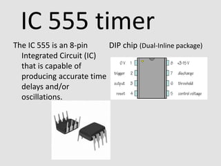
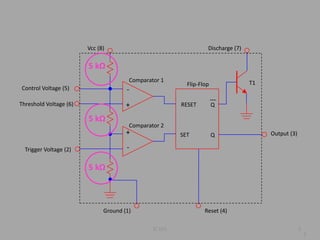
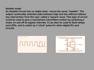
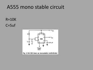
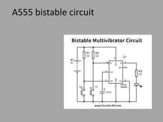
The IC 555 is an 8-pin
Integrated Circuit (IC)
that is capable of
producing accurate time
delays and/or
oscillations.
DIP chip (Dual-Inline package)
IC 555 timer
IC 555 2
Control Voltage (5)
Trigger Voltage (2)
Ground (1)
Vcc (8) Discharge (7)
Reset (4)
Output (3)
-
+
-
+
RESET
SET
Q
Q
Comparator 1
Comparator 2
Flip-Flop T1
2
Threshold Voltage (6)
5 kΩ
5 kΩ
5 kΩ
555 Timer Operating Modes
The 555 has three main operating modes, Monostable,
Astable, and Bistable. Each mode represents a different
type of circuit that has a particular output.
Astable mode
An Astable Circuit has no stable state - hence the name "astable". The
output continually switches state between high and low without without
any intervention from the user, called a 'square' wave. This type of circuit
could be used to give a mechanism intermittent motion by switching a
motor on and off at regular intervals. It can also be used to flash lamps
and LEDs, and is useful as a 'clock' pulse for other digital ICs and
circuits.
Monostable mode
A Monostable Circuit produces one pulse of a set length in response to a
trigger input such as a push button. The output of the circuit stays in the low
state until there is a trigger input, hence the name "monostable" meaning "one
stable state". his type of circuit is ideal for use in a "push to operate" system for
a model displayed at exhibitions. A visitor can push a button to start a model's
mechanism moving, and the mechanism will automatically switch off after a set
time.
Bistable Mode (or Schmitt Trigger)
A Bistable Mode or what is sometimes called a Schmitt Trigger, has two stable
states, high and low. Taking the Trigger input low makes the output of the circuit
go into the high state. Taking the Reset input low makes the output of the circuit
go into the low state. This type of circuit is ideal for use in an automated model
railway system where the train is required to run back and forth over the same
piece of track. A push button (or reed switch with a magnet on the underside of
the train) would be placed at each end of the track so that when one is hit by
the train, it will either trigger or reset the bistable. The output of the 555 would
control a DPDT relay which would be wired as a reversing switch to reverse the
direction of current to the track, thereby reversing the direction of the train
Time Delay Mode
• In the time delay mode, the
delay is controlled by one
external resistor and
capacitor.
Example: Turn a light on in a
delayed amount of time.
(Just turn on or off once)
Oscillator Mode
• In the oscillator mode, the
frequency of oscillation are
controlled with two external
resistors and one capacitor.
Example: Can make a light
flash a specific rate.
(Can turn on and off
repeatedly)
IC 555 timer
Oscillator mode = astable multivibrator mode
Translation: in this mode the IC 555 will continue to
put out pulses until you remove the battery.
(your choice of resistors and capacitors
determines the vibration frequency)
The 555 timer is a two state device: HI and LO
You can be a two state device too……
IC 555 timer
Astable multivibrator mode schematic
Notice:
2 resistors and 1 capacitor
OUTPUT is square wave pulses
LESSON 15
“How the 555 Timer Works”
Period
The Period is the total time of an
on/off cycle and depends on the
values of RA, RB, and C
 
 
   
 C
2
693
.
0
693
.
0
693
.
0
693
.
0
693
.
0
B
A
B
B
A
LOW
HIGH
B
LOW
B
A
HIGH
R
R
T
C
R
C
R
R
T
t
t
T
C
R
t
C
R
R
t










Frequency
The frequency of an oscillation
(or anything that exhibits a
repeating pattern) is inversely
proportional to the period
 C
R
2
R
693
.
0
1
F
T
1
F
B
A



Unit of Measure:
cycles/second = Hertz (Hz)
Solution
R1=390Ჲ , R2=180 Ჲ, C=6.8uF
Period
 
 
mSec
534
.
3
T
F
8
.
6
180
2
390
693
.
0
T
C
R
2
R
693
.
0
T B
A










Frequency
Hz
282.941
F
mSec
534
.
3
1
F
T
1
F



Key Points
The 555 timer works with 2 resistors (one of which
is temperature dependent) and 1 capacitor to
establish an oscillation in the circuit.
The 555 timer output has two modes: ON and OFF
and it turns whatever device it is connected to
ON and OFF at a rate that depends on the
changing resistance of the thermistor (which
depends on temperature)!!!
A555 astable circuit
A555 mono stable circuit
R=10K
C=5uf
A555 bistable circuit
Applications of 555 Timer
555 timer is most important integrated circuit (chip) used widely in digital
electronics. Some common uses and application of 555 timer IC are as
follow:
• PWM (Pulse Width Modulation) & PPM (Pulse Position Modulation)
• Duty Cycle Oscillator
• Lamp Dimmer
• To provide Accurate time delays
• As a flip-flop element
• Digital logic probes
• Analog frequency meters
• Quad Timer applications
• Pulse, Waveform, and square wave generation
• Stepped tone & tone burst generator & linear ramp generation
• Tachometers & temperature measurement
• It can be used as monostable multivibrator and astable multivibrator
• DC to DC Converters
• DC Voltage Regulators
• Voltage to Frequency Converter
• Frequency Divider
• Schmitt trigger
• Cable tester
• Pulse detector
• Wiper speed control
• Timer Switch
• Time delay generation, precision timing and sequential timing

IC 555.pptx

  • 1.
    The IC 555is an 8-pin Integrated Circuit (IC) that is capable of producing accurate time delays and/or oscillations. DIP chip (Dual-Inline package) IC 555 timer
  • 2.
    IC 555 2 ControlVoltage (5) Trigger Voltage (2) Ground (1) Vcc (8) Discharge (7) Reset (4) Output (3) - + - + RESET SET Q Q Comparator 1 Comparator 2 Flip-Flop T1 2 Threshold Voltage (6) 5 kΩ 5 kΩ 5 kΩ
  • 3.
    555 Timer OperatingModes The 555 has three main operating modes, Monostable, Astable, and Bistable. Each mode represents a different type of circuit that has a particular output.
  • 4.
    Astable mode An AstableCircuit has no stable state - hence the name "astable". The output continually switches state between high and low without without any intervention from the user, called a 'square' wave. This type of circuit could be used to give a mechanism intermittent motion by switching a motor on and off at regular intervals. It can also be used to flash lamps and LEDs, and is useful as a 'clock' pulse for other digital ICs and circuits.
  • 5.
    Monostable mode A MonostableCircuit produces one pulse of a set length in response to a trigger input such as a push button. The output of the circuit stays in the low state until there is a trigger input, hence the name "monostable" meaning "one stable state". his type of circuit is ideal for use in a "push to operate" system for a model displayed at exhibitions. A visitor can push a button to start a model's mechanism moving, and the mechanism will automatically switch off after a set time.
  • 6.
    Bistable Mode (orSchmitt Trigger) A Bistable Mode or what is sometimes called a Schmitt Trigger, has two stable states, high and low. Taking the Trigger input low makes the output of the circuit go into the high state. Taking the Reset input low makes the output of the circuit go into the low state. This type of circuit is ideal for use in an automated model railway system where the train is required to run back and forth over the same piece of track. A push button (or reed switch with a magnet on the underside of the train) would be placed at each end of the track so that when one is hit by the train, it will either trigger or reset the bistable. The output of the 555 would control a DPDT relay which would be wired as a reversing switch to reverse the direction of current to the track, thereby reversing the direction of the train
  • 7.
    Time Delay Mode •In the time delay mode, the delay is controlled by one external resistor and capacitor. Example: Turn a light on in a delayed amount of time. (Just turn on or off once) Oscillator Mode • In the oscillator mode, the frequency of oscillation are controlled with two external resistors and one capacitor. Example: Can make a light flash a specific rate. (Can turn on and off repeatedly)
  • 8.
    IC 555 timer Oscillatormode = astable multivibrator mode Translation: in this mode the IC 555 will continue to put out pulses until you remove the battery. (your choice of resistors and capacitors determines the vibration frequency) The 555 timer is a two state device: HI and LO You can be a two state device too……
  • 9.
    IC 555 timer Astablemultivibrator mode schematic Notice: 2 resistors and 1 capacitor OUTPUT is square wave pulses LESSON 15 “How the 555 Timer Works”
  • 10.
    Period The Period isthe total time of an on/off cycle and depends on the values of RA, RB, and C          C 2 693 . 0 693 . 0 693 . 0 693 . 0 693 . 0 B A B B A LOW HIGH B LOW B A HIGH R R T C R C R R T t t T C R t C R R t          
  • 11.
    Frequency The frequency ofan oscillation (or anything that exhibits a repeating pattern) is inversely proportional to the period  C R 2 R 693 . 0 1 F T 1 F B A    Unit of Measure: cycles/second = Hertz (Hz)
  • 12.
    Solution R1=390Ჲ , R2=180Ჲ, C=6.8uF Period     mSec 534 . 3 T F 8 . 6 180 2 390 693 . 0 T C R 2 R 693 . 0 T B A           Frequency Hz 282.941 F mSec 534 . 3 1 F T 1 F   
  • 13.
    Key Points The 555timer works with 2 resistors (one of which is temperature dependent) and 1 capacitor to establish an oscillation in the circuit. The 555 timer output has two modes: ON and OFF and it turns whatever device it is connected to ON and OFF at a rate that depends on the changing resistance of the thermistor (which depends on temperature)!!!
  • 14.
  • 15.
    A555 mono stablecircuit R=10K C=5uf
  • 16.
  • 17.
    Applications of 555Timer 555 timer is most important integrated circuit (chip) used widely in digital electronics. Some common uses and application of 555 timer IC are as follow: • PWM (Pulse Width Modulation) & PPM (Pulse Position Modulation) • Duty Cycle Oscillator • Lamp Dimmer • To provide Accurate time delays • As a flip-flop element • Digital logic probes • Analog frequency meters • Quad Timer applications • Pulse, Waveform, and square wave generation
  • 18.
    • Stepped tone& tone burst generator & linear ramp generation • Tachometers & temperature measurement • It can be used as monostable multivibrator and astable multivibrator • DC to DC Converters • DC Voltage Regulators • Voltage to Frequency Converter • Frequency Divider • Schmitt trigger • Cable tester • Pulse detector • Wiper speed control • Timer Switch • Time delay generation, precision timing and sequential timing