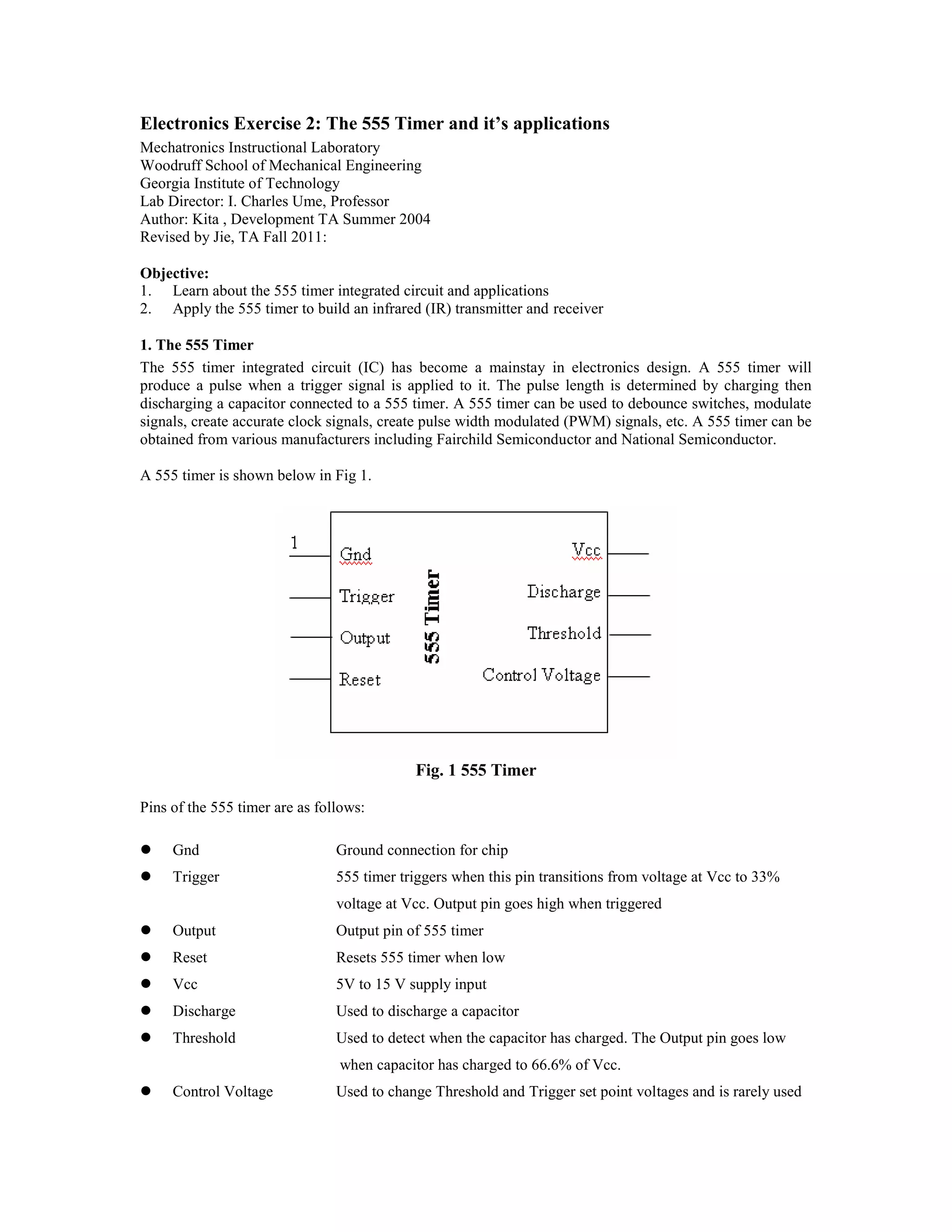
The document describes the 555 timer integrated circuit and its applications, including using it in a
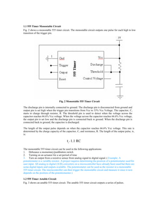
monostable circuit to debounce switches, in an astable circuit to create pulse trains, and to modulate an
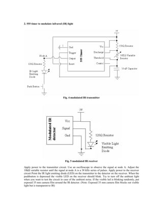
infrared transmitter and receiver circuit by generating a 38 kHz pulse train to transmit data over infrared light.
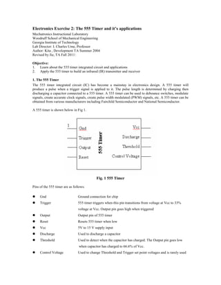
It provides details on the pins and functions of the 555 timer, equations to calculate pulse lengths for the
monostable and astable circuits, and examples of uses for each type of 555 timer circuit configuration.