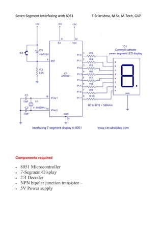
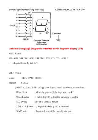
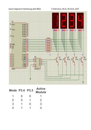
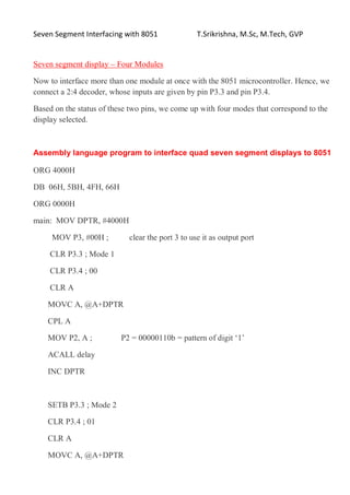
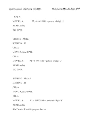
Seven Segment Interfacing with 8051 T.Srikrishna, M.Sc, M.Tech, GVP
Seven segment interfacing with 8051
The name 7 segments imply there are 7 LED segments arranged as shown
Seven segment displays are used to display digits from 0 to 9 and they also
display letters A to F
Working
There are two main constructions of the seven-segment display modules
Common Cathode: In this type of segments all the cathode terminals are
made common and tied to GND. Thus the segments a to g needs a logic
High signal(5v) in order to glow.
Common Anode: In this type of segments all the anodes terminals are
made common and tied to VCC(5v). Thus the segments a to g needs a
logic LOW signal(GND) in order to glow.
Seven Segment Interfacing with 8051 T.Srikrishna, M.Sc, M.Tech, GVP
Components required
 8051 Microcontroller
 7-Segment-Display
 2:4 Decoder
 NPN bipolar junction transistor –
 5V Power supply
Seven Segment Interfacing with 8051 T.Srikrishna, M.Sc, M.Tech, GVP
We will have two lookup tables that have values that are the
complement of each other depending on whether we are using common
anode/common cathode type seven-segment display.
Seven Segment Interfacing with 8051 T.Srikrishna, M.Sc, M.Tech, GVP
Assembly language program to interface seven segment display (0-9)
ORG 4000H
DB: 3FH, 06H, 5BH, 4FH, 66H, 6DH, 7DH, 07H, 7FH, 6FH, 0
; Lookup table for digits 0 to 9
ORG 0000H
main: MOV DPTR, #4000H
Repeat: CLR A
MOVC A, @A+DPTR ; Copy data from external location to accumulator
MOV P1, A ; Move the pattern of the digit into port P2
ACALL delay ; Call a delay to so that the transition is visible
INC DPTR ; Point to the next pattern
CJNE A, 0, Repeat ; Repeat till 0 (Stop bit) is received
SJMP main ; Run this forever till externally stopped
Seven Segment Interfacing with 8051 T.Srikrishna, M.Sc, M.Tech, GVP
Mode P3.4 P3.3
Active
Module
1 0 0 1
2 0 1 2
3 1 0 3
4 1 1 4
Seven Segment Interfacing with 8051 T.Srikrishna, M.Sc, M.Tech, GVP
Seven segment display – Four Modules
Now to interface more than one module at once with the 8051 microcontroller. Hence, we
connect a 2:4 decoder, whose inputs are given by pin P3.3 and pin P3.4.
Based on the status of these two pins, we come up with four modes that correspond to the
display selected.
Assembly language program to interface quad seven segment displays to 8051
ORG 4000H
DB 06H, 5BH, 4FH, 66H
ORG 0000H
main: MOV DPTR, #4000H
MOV P3, #00H ; clear the port 3 to use it as output port
CLR P3.3 ; Mode 1
CLR P3.4 ; 00
CLR A
MOVC A, @A+DPTR
CPL A
MOV P2, A ; P2 = 00000110b = pattern of digit ‘1’
ACALL delay
INC DPTR
SETB P3.3 ; Mode 2
CLR P3.4 ; 01
CLR A
MOVC A, @A+DPTR
Seven Segment Interfacing with 8051 T.Srikrishna, M.Sc, M.Tech, GVP
CPL A
MOV P2, A ; P2 = 01011011b = pattern of digit ‘2’
ACALL delay
INC DPTR
CLR P3.3 ; Mode 3
SETB P3.4 ; 10
CLR A
MOVC A, @A+DPTR
CPL A
MOV P2, A ; P2 = 01001111b = pattern of digit ‘3’
ACALL delay
INC DPTR
SETB P3.3 ; Mode 4
SETB P3.3 ; 11
CLR A
MOVC A, @A+DPTR
CPL A
MOV P2, A ; P2 = 01100110b = pattern of digit ‘4’
ACALL delay
SJMP main ; Run this program forever

Seven segment interfacing with 8051.pdf

  • 1.
    Seven Segment Interfacingwith 8051 T.Srikrishna, M.Sc, M.Tech, GVP Seven segment interfacing with 8051 The name 7 segments imply there are 7 LED segments arranged as shown Seven segment displays are used to display digits from 0 to 9 and they also display letters A to F Working There are two main constructions of the seven-segment display modules Common Cathode: In this type of segments all the cathode terminals are made common and tied to GND. Thus the segments a to g needs a logic High signal(5v) in order to glow. Common Anode: In this type of segments all the anodes terminals are made common and tied to VCC(5v). Thus the segments a to g needs a logic LOW signal(GND) in order to glow.
  • 2.
    Seven Segment Interfacingwith 8051 T.Srikrishna, M.Sc, M.Tech, GVP Components required  8051 Microcontroller  7-Segment-Display  2:4 Decoder  NPN bipolar junction transistor –  5V Power supply
  • 3.
    Seven Segment Interfacingwith 8051 T.Srikrishna, M.Sc, M.Tech, GVP We will have two lookup tables that have values that are the complement of each other depending on whether we are using common anode/common cathode type seven-segment display.
  • 4.
    Seven Segment Interfacingwith 8051 T.Srikrishna, M.Sc, M.Tech, GVP Assembly language program to interface seven segment display (0-9) ORG 4000H DB: 3FH, 06H, 5BH, 4FH, 66H, 6DH, 7DH, 07H, 7FH, 6FH, 0 ; Lookup table for digits 0 to 9 ORG 0000H main: MOV DPTR, #4000H Repeat: CLR A MOVC A, @A+DPTR ; Copy data from external location to accumulator MOV P1, A ; Move the pattern of the digit into port P2 ACALL delay ; Call a delay to so that the transition is visible INC DPTR ; Point to the next pattern CJNE A, 0, Repeat ; Repeat till 0 (Stop bit) is received SJMP main ; Run this forever till externally stopped
  • 5.
    Seven Segment Interfacingwith 8051 T.Srikrishna, M.Sc, M.Tech, GVP Mode P3.4 P3.3 Active Module 1 0 0 1 2 0 1 2 3 1 0 3 4 1 1 4
  • 6.
    Seven Segment Interfacingwith 8051 T.Srikrishna, M.Sc, M.Tech, GVP Seven segment display – Four Modules Now to interface more than one module at once with the 8051 microcontroller. Hence, we connect a 2:4 decoder, whose inputs are given by pin P3.3 and pin P3.4. Based on the status of these two pins, we come up with four modes that correspond to the display selected. Assembly language program to interface quad seven segment displays to 8051 ORG 4000H DB 06H, 5BH, 4FH, 66H ORG 0000H main: MOV DPTR, #4000H MOV P3, #00H ; clear the port 3 to use it as output port CLR P3.3 ; Mode 1 CLR P3.4 ; 00 CLR A MOVC A, @A+DPTR CPL A MOV P2, A ; P2 = 00000110b = pattern of digit ‘1’ ACALL delay INC DPTR SETB P3.3 ; Mode 2 CLR P3.4 ; 01 CLR A MOVC A, @A+DPTR
  • 7.
    Seven Segment Interfacingwith 8051 T.Srikrishna, M.Sc, M.Tech, GVP CPL A MOV P2, A ; P2 = 01011011b = pattern of digit ‘2’ ACALL delay INC DPTR CLR P3.3 ; Mode 3 SETB P3.4 ; 10 CLR A MOVC A, @A+DPTR CPL A MOV P2, A ; P2 = 01001111b = pattern of digit ‘3’ ACALL delay INC DPTR SETB P3.3 ; Mode 4 SETB P3.3 ; 11 CLR A MOVC A, @A+DPTR CPL A MOV P2, A ; P2 = 01100110b = pattern of digit ‘4’ ACALL delay SJMP main ; Run this program forever