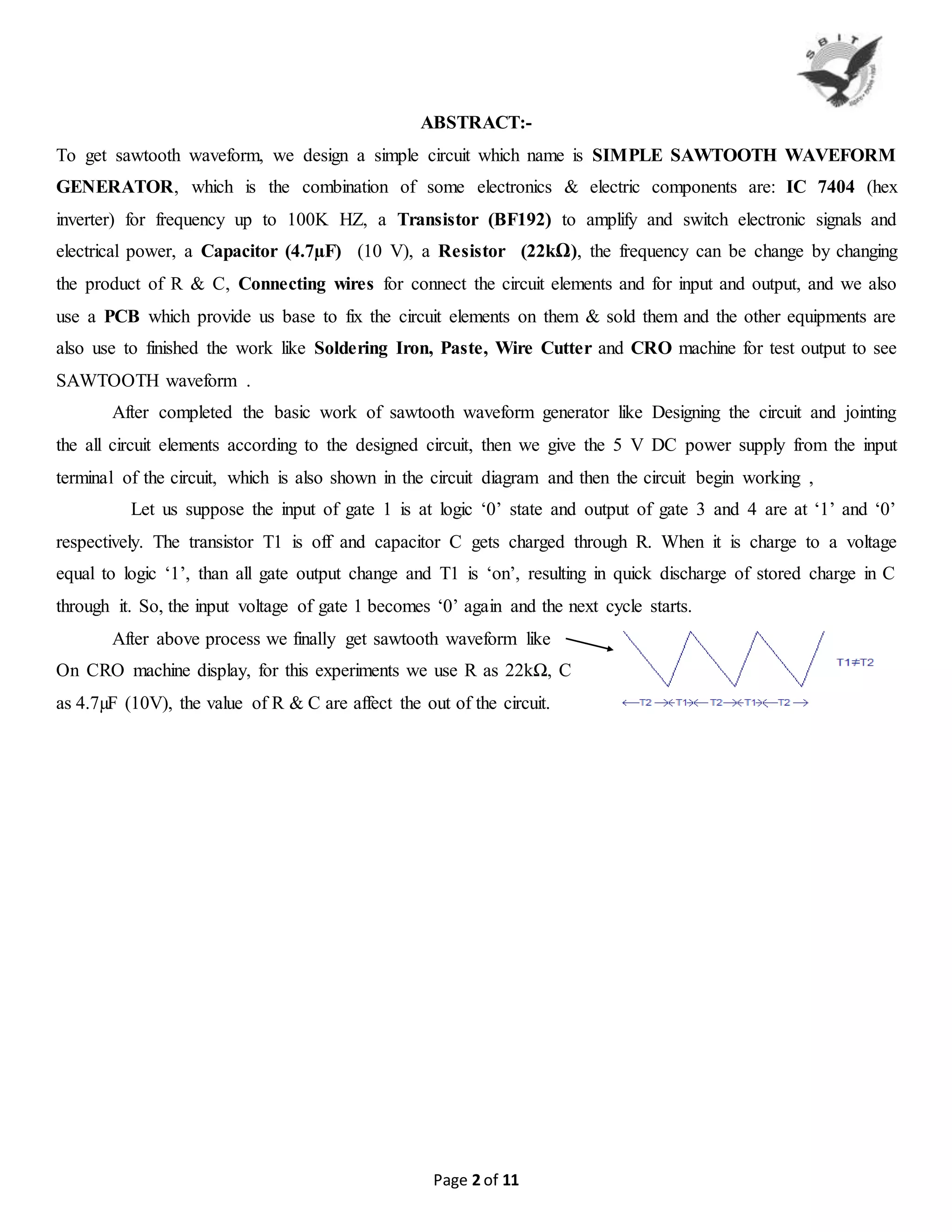
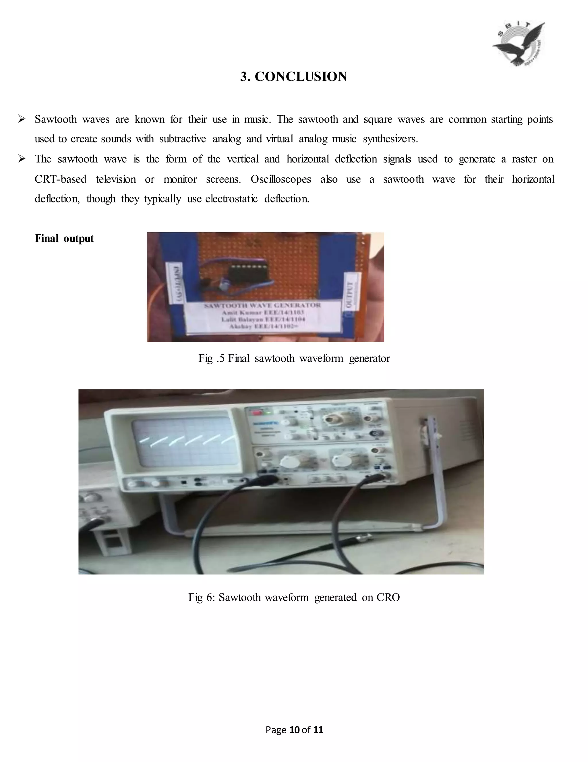
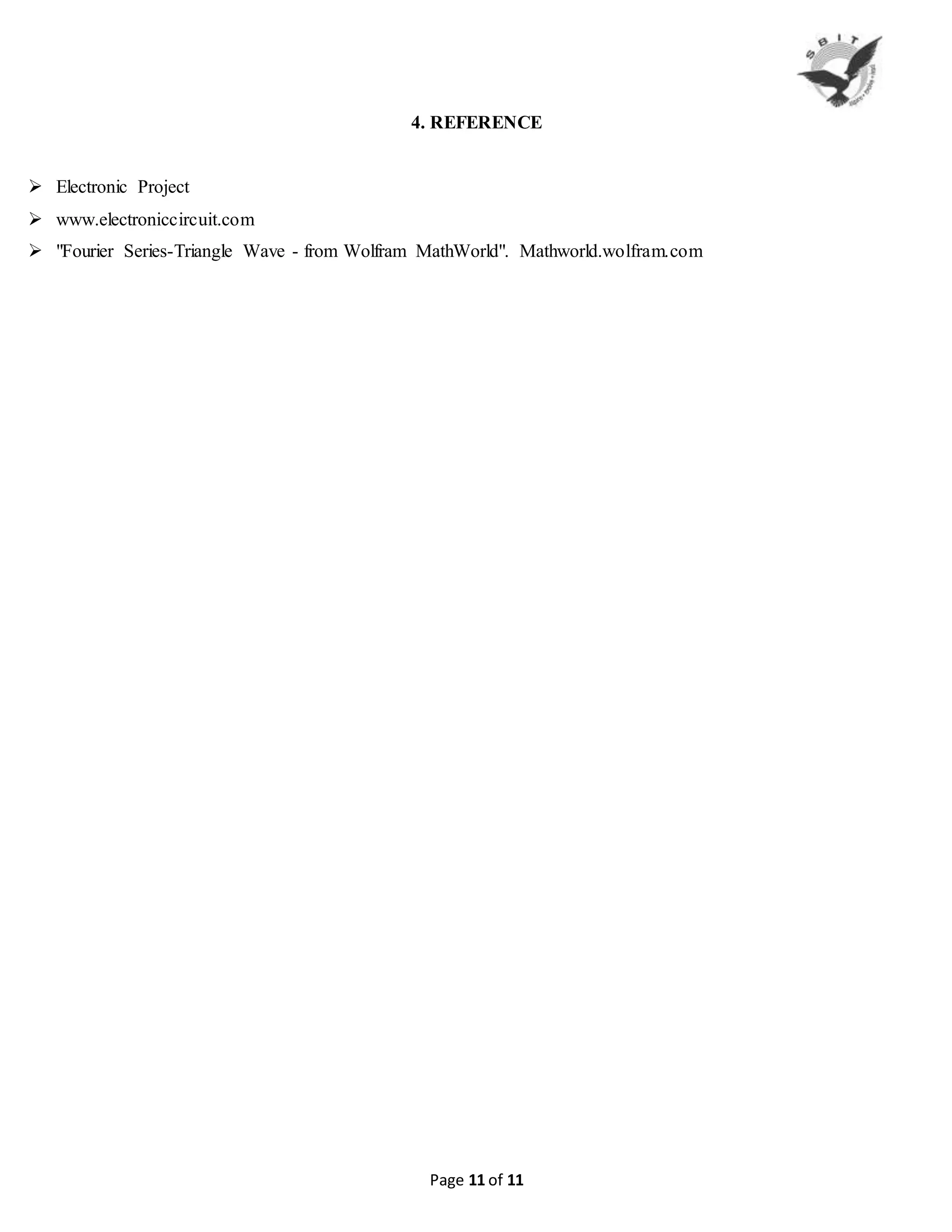
SlideShare a Scribd company logo
Page 1 of 11
REPORT ON
Generation of SAWTOOTH WAVEFORMS
Submitted by:-
Amit kumar Parshad (EEE/14/1103)
Lalit Balayan (EEE/14/1104)
Nitish Kumar (EEE/14/1105)
Department of Electrical and Electronic Engineering
SHRI BALWANT INSTITUTE OF TECHNOLOGY
Approved by AICTE, Min of HRD, Gov of India & DTE, Govt of Haryana
Affiliated to DCR University of Science and Technology, Murthal, Sonepat
Meeru Road (Pallri), Near DPS, Sonepat-131001, Haryana
Page 2 of 11
ABSTRACT:-
To get sawtooth waveform, we design a simple circuit which name is SIMPLE SAWTOOTH WAVEFORM
GENERATOR, which is the combination of some electronics & electric components are: IC 7404 (hex
inverter) for frequency up to 100K HZ, a Transistor (BF192) to amplify and switch electronic signals and
electrical power, a Capacitor (4.7µF) (10 V), a Resistor (22kΩ), the frequency can be change by changing
the product of R & C, Connecting wires for connect the circuit elements and for input and output, and we also
use a PCB which provide us base to fix the circuit elements on them & sold them and the other equipments are
also use to finished the work like Soldering Iron, Paste, Wire Cutter and CRO machine for test output to see
SAWTOOTH waveform .
After completed the basic work of sawtooth waveform generator like Designing the circuit and jointing
the all circuit elements according to the designed circuit, then we give the 5 V DC power supply from the input
terminal of the circuit, which is also shown in the circuit diagram and then the circuit begin working ,
Let us suppose the input of gate 1 is at logic ‘0’ state and output of gate 3 and 4 are at ‘1’ and ‘0’
respectively. The transistor T1 is off and capacitor C gets charged through R. When it is charge to a voltage
equal to logic ‘1’, than all gate output change and T1 is ‘on’, resulting in quick discharge of stored charge in C
through it. So, the input voltage of gate 1 becomes ‘0’ again and the next cycle starts.
After above process we finally get sawtooth waveform like
On CRO machine display, for this experiments we use R as 22kΩ, C
as 4.7µF (10V), the value of R & C are affect the out of the circuit.
Page 3 of 11
CERTIFICATE
This is to certify that the Bridge Course entitled as SIMPLE SAWTOOTH WAVE FORMS GENERATOR
and submitted by AMIT KUMAR PRASHAD having Roll No EEE/14/1103, NITISH KUMAR having Roll
No EEE/14/1105, LALIT BALAYAN having Roll No EEE/14/1104, embodies the bonafide work done by
them under my supervision. Their conduct and behavior is satisfactory.
Signature of the Supervisor
Place: SBIT, SONEPAT
Date:
Page 4 of 11
TABLE OF CONTENTS
1. INTRODUCTION……………………………………………………………………...............6
 Sawtooth waveform ……………………………………………………………………………............................6
 Triangular waveform ……………………………………………………………………………………………..6
2. DESCRIPTION…………………………………………………………………………..........7
 Simple sawtooth wave form …………………………………………………………………………...................7
 Method 2 ……………………………………………………………………………………………....................8
 Application ………………………………………………………………………………………….....................9
3. CONCLUSION……………………………………………………………………………….10
4. REFERENCES………………………………………………………………………………..11
Page 5 of 11
LIST OF FIGURES
1. Fig.(1) Saw tooth waveform ...…………………………………………………………………….……………..6
2. Fig.(2) Triangular waveform ……………………………………………………………………….…................6
3. Fig(3) Simple sawtooth waveform generator ……………………………………………………..…...................7
4. Fig(4) Alternate Simple sawtooth waveform generator …………………………………………………...…......8
5. Fig (5) Final Circuit ………………………….…………………………………………………………..….......10
6. Fig(6) Final sawtooth wave on CRO……………………………………………………………………..….......10
Page 6 of 11
1. INTRODUCTION
1.1- Saw tooth wave generator:
Many people often get confused between saw tooth wave and a triangular wave.
1.2- Saw tooth waveform:-
Saw tooth waveform is a type of linear non sinusoidal waveform with a triangular shape in which the rise time
and fall time are different.
Fig.1 Sawtooth waveform
1.3- Triangular waveform:-
A pure triangular waveform is is also linear, non sinusoidal and have a triangular shape but it has equal rise and
fall times. The saw tooth waveform can also be called an asymmetric triangular wave.
The graphical representation of a triangular and sawtooth waveform is shown in the figure below. T1 is
assumed to be the rise time and T2 is assumed to be the fall time.
Fig.2 Triangular waveform
Like triangular waveforms, sawtooth waveforms are also used in applications like thyristor (SCR, triac etc)
switching, sampling, tone/frequency generation, modulation etc.
Page 7 of 11
2. DESCRIPTION
2.1- Simple Sawtooth Generator
This is used to generate sawtooth wave after giving input voltage.
This easy-to-make sawtooth generator circuit uses one inverter chip and a transistor .IC 7404 (hex
Inverter) is used for frequencies up to 100 k HZ and IC 74S04 (schottky TTL) for frequencies between 100 kHz
and 20 MHz. The frequency can be changed by changing the product of RC.
Let us suppose the input of gate 1 is at logic ‘0’ state and output of gate 3 and 4 are at ‘1’ and ‘0’
respectively. The transistor T1 is off and capacitor C gets charged through R.
Fig .3 Simple sawtooth waveform generator
When it is charge to a voltage equal to logic ‘1’, than all gate output change and T1 is ‘on’, resulting in quick
discharge of stored charge in C through it. So, the input voltage of gate 1 becomes ‘0’ again and the next cycle
starts.
One should choose values of R and C such that the time needed to charge capacitor C from logic ‘0’ to
logic ‘1’states is slightly less than the time period of oscillation. This circuit works efficiently, especially at high
frequencies, provided stray capacitances and inductance are very small.
NOTE:-
‘R’ was taken as 22kΩ, ‘C’ as 4.7µF (10V) for testing to see the sawtooth waveform.
METHOD -2
Page 8 of 11
2.2-Sawtooth wave generator using NE555 timer and uA741 Opamp.
Sawtooth waveforms can be generated by integrating square waves with unequal rise and fall times
(asymmetrical square waves). The circuit shown below shows a setup for generating sawtooth wave. Here an
NE555 timer IC is used for generating the assymmetric square wave and opamp integrator based on uA741 is
used for integrating the assymmetric square wave. The circuit diagram is shown below.
Fig 4: Alternate circuit digram for Sawtooth wave generator.
Here the IC NE555 is wired as a stable multi vibrator with unequal ON and OFF times. The resistor R1, R2 and
capacitor C2 sets the ON and OFF time periods. The value of these components are so selected that the OFF
time is less than 10% of the ON times. The asymmetric square wave is available at pin 3 of the IC. The working
of the a stable multi vibrator is given below.
When the power supply is switched ON, capacitor C1 starts charging through resistors R1 and R2. When the
voltage across C1 is above 2/3Vcc the upper comparator inside the NE555 swings to positive saturation and this
triggers the internal flip-flop. This makes the output (pin 3) of the timer low. Now the capacitor C1 starts to
discharge through resistor R2 into pin 7 of the IC. When the voltage across capacitor C1 becomes less than
1/3Vcc, the lower comparator inside the IC switches to positive saturation and this again triggers the internal
flip-flop. As a result the output of the timer (pin 3) goes low. This action is repeated and the result will be a
square wave at pin 3 of the NE555.
The charging time period (ON time) is given by the equation
Page 9 of 11
T1= 0.69(R1+R2)C1
And the discharging time period (OFF time) is given by the equation
T2=0.69R2C1.
NE555 as astable multivibrator for a better understanding on NE555 based astable multivibrators.
The assymmetric square wave obtained at the output of NE555 is integrated by the inverting active integrator
based on opamp IC uA741. Resistors R3 and R4 sets the gain of the opamp integrator. Resistor R4 in
conjunction with capacitor C3 sets the bandwidth. Since the integrator is wired in inverting mode, the sawtooth
wavform falls when the timer output is high and rises when the timer output is low. Read this article: Triangular
wave generator for a better understanding on opamp integrators.
2.3- APPLICATIONS
 Sawtooth waves are known for their use in music. The sawtooth and square waves are common starting points
used to create sounds with subtractive analog and virtual analog music synthesizers.
 The sawtooth wave is the form of the vertical and horizontal deflection signals used to generate a raster on
CRT-based television or monitor screens. Oscilloscopes also use a sawtooth wave for their horizontal
deflection, though they typically use electrostatic deflection.
 On the wave's "ramp", the magnetic field produced by the deflection yoke drags the electron beam across the
face of the CRT, creating a scan line.
 On the wave's "cliff", the magnetic field suddenly collapses, causing the electron beam to return to its resting
position as quickly as possible.
 The voltage applied to the deflection yoke is adjusted by various means (transformers, capacitors, center-tapped
windings) so that the half-way voltage on the sawtooth's cliff is at the zero mark, meaning that a negative
voltage will cause deflection in one direction, and a positive voltage deflection in the other; thus, a center-
mounted deflection yoke can use the whole screen area to depict a traceThe vertical deflection system operates
the same way as the horizontal, though at a much lower frequency (59.94 Hz on NTSC, 50 Hz for PAL and
SECAM).
 The ramp portion of the wave must appear as a straight line. If otherwise, it indicates that the voltage isn't
increasing linearly and therefore that the magnetic field produced by the deflection yoke is not linear. As a
result, the electron beam will accelerate during the non-linear portions. This would result in a television image
"squished" in the direction of the non-linearity. Extreme cases will show marked brightness increases, since the
electron beam spends more time on that side of the picture.
Page 10 of 11
3. CONCLUSION
 Sawtooth waves are known for their use in music. The sawtooth and square waves are common starting points
used to create sounds with subtractive analog and virtual analog music synthesizers.
 The sawtooth wave is the form of the vertical and horizontal deflection signals used to generate a raster on
CRT-based television or monitor screens. Oscilloscopes also use a sawtooth wave for their horizontal
deflection, though they typically use electrostatic deflection.
Final output
Fig .5 Final sawtooth waveform generator
Fig 6: Sawtooth waveform generated on CRO
Page 11 of 11
4. REFERENCE
 Electronic Project
 www.electroniccircuit.com
 "Fourier Series-Triangle Wave - from Wolfram MathWorld". Mathworld.wolfram.com

More Related Content

What's hot

Ideal Transformers
           Ideal Transformers           Ideal Transformers
Ideal Transformers
masum heera
 
Amplitude modulation & demodulation
Amplitude modulation & demodulation Amplitude modulation & demodulation
Amplitude modulation & demodulation
Bikz013
 
Three phase Induction Motor (Construction and working Principle)
Three phase Induction Motor (Construction and working Principle)Three phase Induction Motor (Construction and working Principle)
Three phase Induction Motor (Construction and working Principle)
Sharmitha Dhanabalan
 
Modulation by sanjay
Modulation by sanjay Modulation by sanjay
Modulation by sanjay Sanjay Songra
 
Basics of amplifier.ppt
Basics of amplifier.pptBasics of amplifier.ppt
Basics of amplifier.ppt
Vijay Togadiya
 
Construction & E.M.F. eqn. of transformer
Construction & E.M.F. eqn. of transformerConstruction & E.M.F. eqn. of transformer
Construction & E.M.F. eqn. of transformer
Jay Baria
 
L14 self and mutual inductance
L14   self and mutual inductanceL14   self and mutual inductance
L14 self and mutual inductanceSatyakam
 
Single phase transformer
Single phase transformerSingle phase transformer
Single phase transformer
Mahendra Rajput
 
Ideal voltage & current sources
Ideal voltage & current sourcesIdeal voltage & current sources
Ideal voltage & current sources
Anil Kumar
 
Hall effect
Hall effectHall effect
Hall effect
Zahra Saman
 
Chapter 3
Chapter 3Chapter 3
Chapter 3
Yimam Alemu
 
Inductance of transmission line
Inductance of transmission lineInductance of transmission line
Inductance of transmission line
Anisur Rahman
 
Power electronics Uncontrolled Rectifiers - Diode Rectifiers
Power electronics   Uncontrolled Rectifiers - Diode RectifiersPower electronics   Uncontrolled Rectifiers - Diode Rectifiers
Power electronics Uncontrolled Rectifiers - Diode Rectifiers
Burdwan University
 
Negative amplifiers and its types Positive feedback and Negative feedback
Negative amplifiers and its types Positive feedback  and Negative feedbackNegative amplifiers and its types Positive feedback  and Negative feedback
Negative amplifiers and its types Positive feedback and Negative feedback
imtiazalijoono
 
Types of dc generator
Types of dc generatorTypes of dc generator
Types of dc generator
Rajal Patel
 
A.c circuits
A.c circuitsA.c circuits
A.c circuits
RONAK SUTARIYA
 
Analog circuits-lab-possible-viva-questions
Analog circuits-lab-possible-viva-questionsAnalog circuits-lab-possible-viva-questions
Analog circuits-lab-possible-viva-questions
padmajasiva
 
Moving iron (MI) instruments
Moving iron (MI) instrumentsMoving iron (MI) instruments
Moving iron (MI) instruments
Chandan Singh
 

What's hot (20)

Ideal Transformers
           Ideal Transformers           Ideal Transformers
Ideal Transformers
 
Amplitude modulation & demodulation
Amplitude modulation & demodulation Amplitude modulation & demodulation
Amplitude modulation & demodulation
 
Three phase Induction Motor (Construction and working Principle)
Three phase Induction Motor (Construction and working Principle)Three phase Induction Motor (Construction and working Principle)
Three phase Induction Motor (Construction and working Principle)
 
Modulation by sanjay
Modulation by sanjay Modulation by sanjay
Modulation by sanjay
 
Basics of amplifier.ppt
Basics of amplifier.pptBasics of amplifier.ppt
Basics of amplifier.ppt
 
Construction & E.M.F. eqn. of transformer
Construction & E.M.F. eqn. of transformerConstruction & E.M.F. eqn. of transformer
Construction & E.M.F. eqn. of transformer
 
L14 self and mutual inductance
L14   self and mutual inductanceL14   self and mutual inductance
L14 self and mutual inductance
 
Single phase transformer
Single phase transformerSingle phase transformer
Single phase transformer
 
Ideal voltage & current sources
Ideal voltage & current sourcesIdeal voltage & current sources
Ideal voltage & current sources
 
Hall effect
Hall effectHall effect
Hall effect
 
Chapter 3
Chapter 3Chapter 3
Chapter 3
 
Inductance of transmission line
Inductance of transmission lineInductance of transmission line
Inductance of transmission line
 
Dc motor
Dc motorDc motor
Dc motor
 
Power electronics Uncontrolled Rectifiers - Diode Rectifiers
Power electronics   Uncontrolled Rectifiers - Diode RectifiersPower electronics   Uncontrolled Rectifiers - Diode Rectifiers
Power electronics Uncontrolled Rectifiers - Diode Rectifiers
 
Negative amplifiers and its types Positive feedback and Negative feedback
Negative amplifiers and its types Positive feedback  and Negative feedbackNegative amplifiers and its types Positive feedback  and Negative feedback
Negative amplifiers and its types Positive feedback and Negative feedback
 
Types of dc generator
Types of dc generatorTypes of dc generator
Types of dc generator
 
A.c circuits
A.c circuitsA.c circuits
A.c circuits
 
Dc fed chopper
Dc fed chopperDc fed chopper
Dc fed chopper
 
Analog circuits-lab-possible-viva-questions
Analog circuits-lab-possible-viva-questionsAnalog circuits-lab-possible-viva-questions
Analog circuits-lab-possible-viva-questions
 
Moving iron (MI) instruments
Moving iron (MI) instrumentsMoving iron (MI) instruments
Moving iron (MI) instruments
 

Similar to Report on sawtooth wave generator

Short notes on digital electronics for specialist officer it exam by das sir,...
Short notes on digital electronics for specialist officer it exam by das sir,...Short notes on digital electronics for specialist officer it exam by das sir,...
Short notes on digital electronics for specialist officer it exam by das sir,...
Tamal Kumar Das
 
Auto Control for Three Phase Induction Motor
Auto Control for Three Phase Induction MotorAuto Control for Three Phase Induction Motor
Auto Control for Three Phase Induction Motor
ijiert bestjournal
 
CRO and FG.ppt
CRO and FG.pptCRO and FG.ppt
CRO and FG.ppt
AnaniahDurai1
 
Cro (emmi) (1)
Cro (emmi) (1)Cro (emmi) (1)
Cro (emmi) (1)
Ravi Anand
 
Design and Implementation of Schmitt Trigger using Operational Amplifier
Design and Implementation of Schmitt Trigger using Operational AmplifierDesign and Implementation of Schmitt Trigger using Operational Amplifier
Design and Implementation of Schmitt Trigger using Operational Amplifier
IJERA Editor
 
Power converter lab manual by chaturvedula
Power converter lab manual by chaturvedulaPower converter lab manual by chaturvedula
Power converter lab manual by chaturvedula
KumarChaturvedula
 
Unit-III Waveform Generator
Unit-III Waveform GeneratorUnit-III Waveform Generator
Unit-III Waveform Generator
Dr.Raja R
 
236793460 ee6361-electric-circuit-lab-docx
236793460 ee6361-electric-circuit-lab-docx236793460 ee6361-electric-circuit-lab-docx
236793460 ee6361-electric-circuit-lab-docx
homeworkping3
 
Function Generator
Function GeneratorFunction Generator
Function Generatorraj singh
 
Pulse & Digital Circuits
Pulse & Digital CircuitsPulse & Digital Circuits
Pulse & Digital Circuits
SRAVANIP22
 
Phase Shift, Collpitt's and Crystal oscillators.pptx
Phase Shift, Collpitt's and Crystal oscillators.pptxPhase Shift, Collpitt's and Crystal oscillators.pptx
Phase Shift, Collpitt's and Crystal oscillators.pptx
ProfVilasShamraoPati
 
LIC UNIT V.pptx
LIC UNIT V.pptxLIC UNIT V.pptx
LIC UNIT V.pptx
ArunS118525
 
B230918
B230918B230918
synchronous machine construction
synchronous machine construction synchronous machine construction
synchronous machine construction
manish9888
 
NEET coaching class in Mumbai
NEET coaching class in MumbaiNEET coaching class in Mumbai
NEET coaching class in Mumbai
Ekeeda
 
Pulse & Linear Integrated Circuits
Pulse & Linear Integrated CircuitsPulse & Linear Integrated Circuits
Pulse & Linear Integrated Circuits
SRAVANIP22
 
Pbl report kkkl 2174 electric analogue
Pbl report kkkl 2174 electric analoguePbl report kkkl 2174 electric analogue
Pbl report kkkl 2174 electric analogueHakim Futra
 
Speed Control of Synchronous Motor
Speed Control of Synchronous Motor Speed Control of Synchronous Motor
Speed Control of Synchronous Motor
Ashutosh Jha
 
Conducted electromagnetic interference mitigation in super-lift Luo-converte...
Conducted electromagnetic interference mitigation in super-lift  Luo-converte...Conducted electromagnetic interference mitigation in super-lift  Luo-converte...
Conducted electromagnetic interference mitigation in super-lift Luo-converte...
IJECEIAES
 

Similar to Report on sawtooth wave generator (20)

Short notes on digital electronics for specialist officer it exam by das sir,...
Short notes on digital electronics for specialist officer it exam by das sir,...Short notes on digital electronics for specialist officer it exam by das sir,...
Short notes on digital electronics for specialist officer it exam by das sir,...
 
Auto Control for Three Phase Induction Motor
Auto Control for Three Phase Induction MotorAuto Control for Three Phase Induction Motor
Auto Control for Three Phase Induction Motor
 
CRO and FG.ppt
CRO and FG.pptCRO and FG.ppt
CRO and FG.ppt
 
Cro (emmi) (1)
Cro (emmi) (1)Cro (emmi) (1)
Cro (emmi) (1)
 
Design and Implementation of Schmitt Trigger using Operational Amplifier
Design and Implementation of Schmitt Trigger using Operational AmplifierDesign and Implementation of Schmitt Trigger using Operational Amplifier
Design and Implementation of Schmitt Trigger using Operational Amplifier
 
Power converter lab manual by chaturvedula
Power converter lab manual by chaturvedulaPower converter lab manual by chaturvedula
Power converter lab manual by chaturvedula
 
Unit-III Waveform Generator
Unit-III Waveform GeneratorUnit-III Waveform Generator
Unit-III Waveform Generator
 
236793460 ee6361-electric-circuit-lab-docx
236793460 ee6361-electric-circuit-lab-docx236793460 ee6361-electric-circuit-lab-docx
236793460 ee6361-electric-circuit-lab-docx
 
Function Generator
Function GeneratorFunction Generator
Function Generator
 
Pulse & Digital Circuits
Pulse & Digital CircuitsPulse & Digital Circuits
Pulse & Digital Circuits
 
10 win-mech-iv-rev-ie
10 win-mech-iv-rev-ie10 win-mech-iv-rev-ie
10 win-mech-iv-rev-ie
 
Phase Shift, Collpitt's and Crystal oscillators.pptx
Phase Shift, Collpitt's and Crystal oscillators.pptxPhase Shift, Collpitt's and Crystal oscillators.pptx
Phase Shift, Collpitt's and Crystal oscillators.pptx
 
LIC UNIT V.pptx
LIC UNIT V.pptxLIC UNIT V.pptx
LIC UNIT V.pptx
 
B230918
B230918B230918
B230918
 
synchronous machine construction
synchronous machine construction synchronous machine construction
synchronous machine construction
 
NEET coaching class in Mumbai
NEET coaching class in MumbaiNEET coaching class in Mumbai
NEET coaching class in Mumbai
 
Pulse & Linear Integrated Circuits
Pulse & Linear Integrated CircuitsPulse & Linear Integrated Circuits
Pulse & Linear Integrated Circuits
 
Pbl report kkkl 2174 electric analogue
Pbl report kkkl 2174 electric analoguePbl report kkkl 2174 electric analogue
Pbl report kkkl 2174 electric analogue
 
Speed Control of Synchronous Motor
Speed Control of Synchronous Motor Speed Control of Synchronous Motor
Speed Control of Synchronous Motor
 
Conducted electromagnetic interference mitigation in super-lift Luo-converte...
Conducted electromagnetic interference mitigation in super-lift  Luo-converte...Conducted electromagnetic interference mitigation in super-lift  Luo-converte...
Conducted electromagnetic interference mitigation in super-lift Luo-converte...
 

Recently uploaded

The Roman Empire A Historical Colossus.pdf
The Roman Empire A Historical Colossus.pdfThe Roman Empire A Historical Colossus.pdf
The Roman Empire A Historical Colossus.pdf
kaushalkr1407
 
The Accursed House by Émile Gaboriau.pptx
The Accursed House by Émile Gaboriau.pptxThe Accursed House by Émile Gaboriau.pptx
The Accursed House by Émile Gaboriau.pptx
DhatriParmar
 
The basics of sentences session 5pptx.pptx
The basics of sentences session 5pptx.pptxThe basics of sentences session 5pptx.pptx
The basics of sentences session 5pptx.pptx
heathfieldcps1
 
Welcome to TechSoup New Member Orientation and Q&A (May 2024).pdf
Welcome to TechSoup   New Member Orientation and Q&A (May 2024).pdfWelcome to TechSoup   New Member Orientation and Q&A (May 2024).pdf
Welcome to TechSoup New Member Orientation and Q&A (May 2024).pdf
TechSoup
 
Digital Tools and AI for Teaching Learning and Research
Digital Tools and AI for Teaching Learning and ResearchDigital Tools and AI for Teaching Learning and Research
Digital Tools and AI for Teaching Learning and Research
Vikramjit Singh
 
Operation Blue Star - Saka Neela Tara
Operation Blue Star   -  Saka Neela TaraOperation Blue Star   -  Saka Neela Tara
Operation Blue Star - Saka Neela Tara
Balvir Singh
 
Chapter 3 - Islamic Banking Products and Services.pptx
Chapter 3 - Islamic Banking Products and Services.pptxChapter 3 - Islamic Banking Products and Services.pptx
Chapter 3 - Islamic Banking Products and Services.pptx
Mohd Adib Abd Muin, Senior Lecturer at Universiti Utara Malaysia
 
Acetabularia Information For Class 9 .docx
Acetabularia Information For Class 9  .docxAcetabularia Information For Class 9  .docx
Acetabularia Information For Class 9 .docx
vaibhavrinwa19
 
June 3, 2024 Anti-Semitism Letter Sent to MIT President Kornbluth and MIT Cor...
June 3, 2024 Anti-Semitism Letter Sent to MIT President Kornbluth and MIT Cor...June 3, 2024 Anti-Semitism Letter Sent to MIT President Kornbluth and MIT Cor...
June 3, 2024 Anti-Semitism Letter Sent to MIT President Kornbluth and MIT Cor...
Levi Shapiro
 
special B.ed 2nd year old paper_20240531.pdf
special B.ed 2nd year old paper_20240531.pdfspecial B.ed 2nd year old paper_20240531.pdf
special B.ed 2nd year old paper_20240531.pdf
Special education needs
 
Synthetic Fiber Construction in lab .pptx
Synthetic Fiber Construction in lab .pptxSynthetic Fiber Construction in lab .pptx
Synthetic Fiber Construction in lab .pptx
Pavel ( NSTU)
 
TESDA TM1 REVIEWER FOR NATIONAL ASSESSMENT WRITTEN AND ORAL QUESTIONS WITH A...
TESDA TM1 REVIEWER  FOR NATIONAL ASSESSMENT WRITTEN AND ORAL QUESTIONS WITH A...TESDA TM1 REVIEWER  FOR NATIONAL ASSESSMENT WRITTEN AND ORAL QUESTIONS WITH A...
TESDA TM1 REVIEWER FOR NATIONAL ASSESSMENT WRITTEN AND ORAL QUESTIONS WITH A...
EugeneSaldivar
 
Honest Reviews of Tim Han LMA Course Program.pptx
Honest Reviews of Tim Han LMA Course Program.pptxHonest Reviews of Tim Han LMA Course Program.pptx
Honest Reviews of Tim Han LMA Course Program.pptx
timhan337
 
aaaaaaaaaaaaaaaaaaaaaaaaaaaaaaaaaaaaaaaaa
aaaaaaaaaaaaaaaaaaaaaaaaaaaaaaaaaaaaaaaaaaaaaaaaaaaaaaaaaaaaaaaaaaaaaaaaaaaaaaaaaa
aaaaaaaaaaaaaaaaaaaaaaaaaaaaaaaaaaaaaaaaa
siemaillard
 
Biological Screening of Herbal Drugs in detailed.
Biological Screening of Herbal Drugs in detailed.Biological Screening of Herbal Drugs in detailed.
Biological Screening of Herbal Drugs in detailed.
Ashokrao Mane college of Pharmacy Peth-Vadgaon
 
Francesca Gottschalk - How can education support child empowerment.pptx
Francesca Gottschalk - How can education support child empowerment.pptxFrancesca Gottschalk - How can education support child empowerment.pptx
Francesca Gottschalk - How can education support child empowerment.pptx
EduSkills OECD
 
Model Attribute Check Company Auto Property
Model Attribute  Check Company Auto PropertyModel Attribute  Check Company Auto Property
Model Attribute Check Company Auto Property
Celine George
 
The Challenger.pdf DNHS Official Publication
The Challenger.pdf DNHS Official PublicationThe Challenger.pdf DNHS Official Publication
The Challenger.pdf DNHS Official Publication
Delapenabediema
 
Guidance_and_Counselling.pdf B.Ed. 4th Semester
Guidance_and_Counselling.pdf B.Ed. 4th SemesterGuidance_and_Counselling.pdf B.Ed. 4th Semester
Guidance_and_Counselling.pdf B.Ed. 4th Semester
Atul Kumar Singh
 
Adversarial Attention Modeling for Multi-dimensional Emotion Regression.pdf
Adversarial Attention Modeling for Multi-dimensional Emotion Regression.pdfAdversarial Attention Modeling for Multi-dimensional Emotion Regression.pdf
Adversarial Attention Modeling for Multi-dimensional Emotion Regression.pdf
Po-Chuan Chen
 

Recently uploaded (20)

The Roman Empire A Historical Colossus.pdf
The Roman Empire A Historical Colossus.pdfThe Roman Empire A Historical Colossus.pdf
The Roman Empire A Historical Colossus.pdf
 
The Accursed House by Émile Gaboriau.pptx
The Accursed House by Émile Gaboriau.pptxThe Accursed House by Émile Gaboriau.pptx
The Accursed House by Émile Gaboriau.pptx
 
The basics of sentences session 5pptx.pptx
The basics of sentences session 5pptx.pptxThe basics of sentences session 5pptx.pptx
The basics of sentences session 5pptx.pptx
 
Welcome to TechSoup New Member Orientation and Q&A (May 2024).pdf
Welcome to TechSoup   New Member Orientation and Q&A (May 2024).pdfWelcome to TechSoup   New Member Orientation and Q&A (May 2024).pdf
Welcome to TechSoup New Member Orientation and Q&A (May 2024).pdf
 
Digital Tools and AI for Teaching Learning and Research
Digital Tools and AI for Teaching Learning and ResearchDigital Tools and AI for Teaching Learning and Research
Digital Tools and AI for Teaching Learning and Research
 
Operation Blue Star - Saka Neela Tara
Operation Blue Star   -  Saka Neela TaraOperation Blue Star   -  Saka Neela Tara
Operation Blue Star - Saka Neela Tara
 
Chapter 3 - Islamic Banking Products and Services.pptx
Chapter 3 - Islamic Banking Products and Services.pptxChapter 3 - Islamic Banking Products and Services.pptx
Chapter 3 - Islamic Banking Products and Services.pptx
 
Acetabularia Information For Class 9 .docx
Acetabularia Information For Class 9  .docxAcetabularia Information For Class 9  .docx
Acetabularia Information For Class 9 .docx
 
June 3, 2024 Anti-Semitism Letter Sent to MIT President Kornbluth and MIT Cor...
June 3, 2024 Anti-Semitism Letter Sent to MIT President Kornbluth and MIT Cor...June 3, 2024 Anti-Semitism Letter Sent to MIT President Kornbluth and MIT Cor...
June 3, 2024 Anti-Semitism Letter Sent to MIT President Kornbluth and MIT Cor...
 
special B.ed 2nd year old paper_20240531.pdf
special B.ed 2nd year old paper_20240531.pdfspecial B.ed 2nd year old paper_20240531.pdf
special B.ed 2nd year old paper_20240531.pdf
 
Synthetic Fiber Construction in lab .pptx
Synthetic Fiber Construction in lab .pptxSynthetic Fiber Construction in lab .pptx
Synthetic Fiber Construction in lab .pptx
 
TESDA TM1 REVIEWER FOR NATIONAL ASSESSMENT WRITTEN AND ORAL QUESTIONS WITH A...
TESDA TM1 REVIEWER  FOR NATIONAL ASSESSMENT WRITTEN AND ORAL QUESTIONS WITH A...TESDA TM1 REVIEWER  FOR NATIONAL ASSESSMENT WRITTEN AND ORAL QUESTIONS WITH A...
TESDA TM1 REVIEWER FOR NATIONAL ASSESSMENT WRITTEN AND ORAL QUESTIONS WITH A...
 
Honest Reviews of Tim Han LMA Course Program.pptx
Honest Reviews of Tim Han LMA Course Program.pptxHonest Reviews of Tim Han LMA Course Program.pptx
Honest Reviews of Tim Han LMA Course Program.pptx
 
aaaaaaaaaaaaaaaaaaaaaaaaaaaaaaaaaaaaaaaaa
aaaaaaaaaaaaaaaaaaaaaaaaaaaaaaaaaaaaaaaaaaaaaaaaaaaaaaaaaaaaaaaaaaaaaaaaaaaaaaaaaa
aaaaaaaaaaaaaaaaaaaaaaaaaaaaaaaaaaaaaaaaa
 
Biological Screening of Herbal Drugs in detailed.
Biological Screening of Herbal Drugs in detailed.Biological Screening of Herbal Drugs in detailed.
Biological Screening of Herbal Drugs in detailed.
 
Francesca Gottschalk - How can education support child empowerment.pptx
Francesca Gottschalk - How can education support child empowerment.pptxFrancesca Gottschalk - How can education support child empowerment.pptx
Francesca Gottschalk - How can education support child empowerment.pptx
 
Model Attribute Check Company Auto Property
Model Attribute  Check Company Auto PropertyModel Attribute  Check Company Auto Property
Model Attribute Check Company Auto Property
 
The Challenger.pdf DNHS Official Publication
The Challenger.pdf DNHS Official PublicationThe Challenger.pdf DNHS Official Publication
The Challenger.pdf DNHS Official Publication
 
Guidance_and_Counselling.pdf B.Ed. 4th Semester
Guidance_and_Counselling.pdf B.Ed. 4th SemesterGuidance_and_Counselling.pdf B.Ed. 4th Semester
Guidance_and_Counselling.pdf B.Ed. 4th Semester
 
Adversarial Attention Modeling for Multi-dimensional Emotion Regression.pdf
Adversarial Attention Modeling for Multi-dimensional Emotion Regression.pdfAdversarial Attention Modeling for Multi-dimensional Emotion Regression.pdf
Adversarial Attention Modeling for Multi-dimensional Emotion Regression.pdf
 

Report on sawtooth wave generator

  • 1. Page 1 of 11 REPORT ON Generation of SAWTOOTH WAVEFORMS Submitted by:- Amit kumar Parshad (EEE/14/1103) Lalit Balayan (EEE/14/1104) Nitish Kumar (EEE/14/1105) Department of Electrical and Electronic Engineering SHRI BALWANT INSTITUTE OF TECHNOLOGY Approved by AICTE, Min of HRD, Gov of India & DTE, Govt of Haryana Affiliated to DCR University of Science and Technology, Murthal, Sonepat Meeru Road (Pallri), Near DPS, Sonepat-131001, Haryana
  • 2. Page 2 of 11 ABSTRACT:- To get sawtooth waveform, we design a simple circuit which name is SIMPLE SAWTOOTH WAVEFORM GENERATOR, which is the combination of some electronics & electric components are: IC 7404 (hex inverter) for frequency up to 100K HZ, a Transistor (BF192) to amplify and switch electronic signals and electrical power, a Capacitor (4.7µF) (10 V), a Resistor (22kΩ), the frequency can be change by changing the product of R & C, Connecting wires for connect the circuit elements and for input and output, and we also use a PCB which provide us base to fix the circuit elements on them & sold them and the other equipments are also use to finished the work like Soldering Iron, Paste, Wire Cutter and CRO machine for test output to see SAWTOOTH waveform . After completed the basic work of sawtooth waveform generator like Designing the circuit and jointing the all circuit elements according to the designed circuit, then we give the 5 V DC power supply from the input terminal of the circuit, which is also shown in the circuit diagram and then the circuit begin working , Let us suppose the input of gate 1 is at logic ‘0’ state and output of gate 3 and 4 are at ‘1’ and ‘0’ respectively. The transistor T1 is off and capacitor C gets charged through R. When it is charge to a voltage equal to logic ‘1’, than all gate output change and T1 is ‘on’, resulting in quick discharge of stored charge in C through it. So, the input voltage of gate 1 becomes ‘0’ again and the next cycle starts. After above process we finally get sawtooth waveform like On CRO machine display, for this experiments we use R as 22kΩ, C as 4.7µF (10V), the value of R & C are affect the out of the circuit.
  • 3. Page 3 of 11 CERTIFICATE This is to certify that the Bridge Course entitled as SIMPLE SAWTOOTH WAVE FORMS GENERATOR and submitted by AMIT KUMAR PRASHAD having Roll No EEE/14/1103, NITISH KUMAR having Roll No EEE/14/1105, LALIT BALAYAN having Roll No EEE/14/1104, embodies the bonafide work done by them under my supervision. Their conduct and behavior is satisfactory. Signature of the Supervisor Place: SBIT, SONEPAT Date:
  • 4. Page 4 of 11 TABLE OF CONTENTS 1. INTRODUCTION……………………………………………………………………...............6  Sawtooth waveform ……………………………………………………………………………............................6  Triangular waveform ……………………………………………………………………………………………..6 2. DESCRIPTION…………………………………………………………………………..........7  Simple sawtooth wave form …………………………………………………………………………...................7  Method 2 ……………………………………………………………………………………………....................8  Application ………………………………………………………………………………………….....................9 3. CONCLUSION……………………………………………………………………………….10 4. REFERENCES………………………………………………………………………………..11
  • 5. Page 5 of 11 LIST OF FIGURES 1. Fig.(1) Saw tooth waveform ...…………………………………………………………………….……………..6 2. Fig.(2) Triangular waveform ……………………………………………………………………….…................6 3. Fig(3) Simple sawtooth waveform generator ……………………………………………………..…...................7 4. Fig(4) Alternate Simple sawtooth waveform generator …………………………………………………...…......8 5. Fig (5) Final Circuit ………………………….…………………………………………………………..….......10 6. Fig(6) Final sawtooth wave on CRO……………………………………………………………………..….......10
  • 6. Page 6 of 11 1. INTRODUCTION 1.1- Saw tooth wave generator: Many people often get confused between saw tooth wave and a triangular wave. 1.2- Saw tooth waveform:- Saw tooth waveform is a type of linear non sinusoidal waveform with a triangular shape in which the rise time and fall time are different. Fig.1 Sawtooth waveform 1.3- Triangular waveform:- A pure triangular waveform is is also linear, non sinusoidal and have a triangular shape but it has equal rise and fall times. The saw tooth waveform can also be called an asymmetric triangular wave. The graphical representation of a triangular and sawtooth waveform is shown in the figure below. T1 is assumed to be the rise time and T2 is assumed to be the fall time. Fig.2 Triangular waveform Like triangular waveforms, sawtooth waveforms are also used in applications like thyristor (SCR, triac etc) switching, sampling, tone/frequency generation, modulation etc.
  • 7. Page 7 of 11 2. DESCRIPTION 2.1- Simple Sawtooth Generator This is used to generate sawtooth wave after giving input voltage. This easy-to-make sawtooth generator circuit uses one inverter chip and a transistor .IC 7404 (hex Inverter) is used for frequencies up to 100 k HZ and IC 74S04 (schottky TTL) for frequencies between 100 kHz and 20 MHz. The frequency can be changed by changing the product of RC. Let us suppose the input of gate 1 is at logic ‘0’ state and output of gate 3 and 4 are at ‘1’ and ‘0’ respectively. The transistor T1 is off and capacitor C gets charged through R. Fig .3 Simple sawtooth waveform generator When it is charge to a voltage equal to logic ‘1’, than all gate output change and T1 is ‘on’, resulting in quick discharge of stored charge in C through it. So, the input voltage of gate 1 becomes ‘0’ again and the next cycle starts. One should choose values of R and C such that the time needed to charge capacitor C from logic ‘0’ to logic ‘1’states is slightly less than the time period of oscillation. This circuit works efficiently, especially at high frequencies, provided stray capacitances and inductance are very small. NOTE:- ‘R’ was taken as 22kΩ, ‘C’ as 4.7µF (10V) for testing to see the sawtooth waveform. METHOD -2
  • 8. Page 8 of 11 2.2-Sawtooth wave generator using NE555 timer and uA741 Opamp. Sawtooth waveforms can be generated by integrating square waves with unequal rise and fall times (asymmetrical square waves). The circuit shown below shows a setup for generating sawtooth wave. Here an NE555 timer IC is used for generating the assymmetric square wave and opamp integrator based on uA741 is used for integrating the assymmetric square wave. The circuit diagram is shown below. Fig 4: Alternate circuit digram for Sawtooth wave generator. Here the IC NE555 is wired as a stable multi vibrator with unequal ON and OFF times. The resistor R1, R2 and capacitor C2 sets the ON and OFF time periods. The value of these components are so selected that the OFF time is less than 10% of the ON times. The asymmetric square wave is available at pin 3 of the IC. The working of the a stable multi vibrator is given below. When the power supply is switched ON, capacitor C1 starts charging through resistors R1 and R2. When the voltage across C1 is above 2/3Vcc the upper comparator inside the NE555 swings to positive saturation and this triggers the internal flip-flop. This makes the output (pin 3) of the timer low. Now the capacitor C1 starts to discharge through resistor R2 into pin 7 of the IC. When the voltage across capacitor C1 becomes less than 1/3Vcc, the lower comparator inside the IC switches to positive saturation and this again triggers the internal flip-flop. As a result the output of the timer (pin 3) goes low. This action is repeated and the result will be a square wave at pin 3 of the NE555. The charging time period (ON time) is given by the equation
  • 9. Page 9 of 11 T1= 0.69(R1+R2)C1 And the discharging time period (OFF time) is given by the equation T2=0.69R2C1. NE555 as astable multivibrator for a better understanding on NE555 based astable multivibrators. The assymmetric square wave obtained at the output of NE555 is integrated by the inverting active integrator based on opamp IC uA741. Resistors R3 and R4 sets the gain of the opamp integrator. Resistor R4 in conjunction with capacitor C3 sets the bandwidth. Since the integrator is wired in inverting mode, the sawtooth wavform falls when the timer output is high and rises when the timer output is low. Read this article: Triangular wave generator for a better understanding on opamp integrators. 2.3- APPLICATIONS  Sawtooth waves are known for their use in music. The sawtooth and square waves are common starting points used to create sounds with subtractive analog and virtual analog music synthesizers.  The sawtooth wave is the form of the vertical and horizontal deflection signals used to generate a raster on CRT-based television or monitor screens. Oscilloscopes also use a sawtooth wave for their horizontal deflection, though they typically use electrostatic deflection.  On the wave's "ramp", the magnetic field produced by the deflection yoke drags the electron beam across the face of the CRT, creating a scan line.  On the wave's "cliff", the magnetic field suddenly collapses, causing the electron beam to return to its resting position as quickly as possible.  The voltage applied to the deflection yoke is adjusted by various means (transformers, capacitors, center-tapped windings) so that the half-way voltage on the sawtooth's cliff is at the zero mark, meaning that a negative voltage will cause deflection in one direction, and a positive voltage deflection in the other; thus, a center- mounted deflection yoke can use the whole screen area to depict a traceThe vertical deflection system operates the same way as the horizontal, though at a much lower frequency (59.94 Hz on NTSC, 50 Hz for PAL and SECAM).  The ramp portion of the wave must appear as a straight line. If otherwise, it indicates that the voltage isn't increasing linearly and therefore that the magnetic field produced by the deflection yoke is not linear. As a result, the electron beam will accelerate during the non-linear portions. This would result in a television image "squished" in the direction of the non-linearity. Extreme cases will show marked brightness increases, since the electron beam spends more time on that side of the picture.
  • 10. Page 10 of 11 3. CONCLUSION  Sawtooth waves are known for their use in music. The sawtooth and square waves are common starting points used to create sounds with subtractive analog and virtual analog music synthesizers.  The sawtooth wave is the form of the vertical and horizontal deflection signals used to generate a raster on CRT-based television or monitor screens. Oscilloscopes also use a sawtooth wave for their horizontal deflection, though they typically use electrostatic deflection. Final output Fig .5 Final sawtooth waveform generator Fig 6: Sawtooth waveform generated on CRO
  • 11. Page 11 of 11 4. REFERENCE  Electronic Project  www.electroniccircuit.com  "Fourier Series-Triangle Wave - from Wolfram MathWorld". Mathworld.wolfram.com