Downloaded 837 times


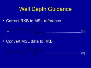

![Wildcat to Development Well
Correlation
where:
• D [m or ft] ... total depth of point of interest in
reference to RKB
• hRKB [m or ft] ... height of RKB above MSL
• Δh [m or ft] ... difference of elevation of RKB1
to RKB2](https://image.slidesharecdn.com/3-140910004046-phpapp01/85/Well-Planning-10-320.jpg)


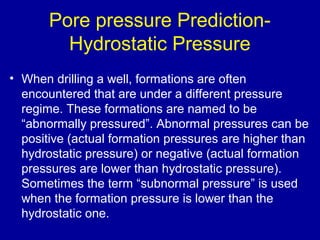
![Pore pressure Prediction-
Hydrostatic Pressure
Where
• ρfl [ppg] ... density of the fluid causing hydrostatic
pressure
• ρ [kg/m3] ... average fluid density
• D [ft] ... depth at which hydrostatic pressure occurs
(TVD)
• h [m] ... vertical height of column of liquid
• p [psi] ... hydrostatic pressure
• g [m/s2] ... acceleration due to gravity](https://image.slidesharecdn.com/3-140910004046-phpapp01/85/Well-Planning-13-320.jpg)


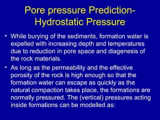
![Pore pressure Prediction-
Hydrostatic Pressure
……………………………………(7)
ob z p s =s +
Where :
σob [psi] ... overburden stress
σz [psi] ... vertical stress supported by the grain-to-grain
connections
p [psi] ... formation pore pressure](https://image.slidesharecdn.com/3-140910004046-phpapp01/85/Well-Planning-19-320.jpg)
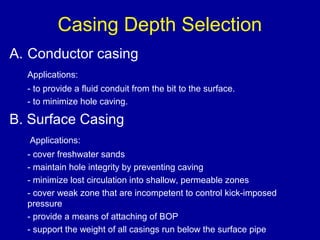
![Pore pressure Prediction-
Hydrostatic Pressure
• The bulk density [ppg] of a formation is
estimated by equation:
……………………………….(8)
r r f r f b g fl = (1- ) +
where:
ρg [ppg] ... grain density
ρfl [ppg] ... formation fluid density
f [1] ... total porosity of the formation](https://image.slidesharecdn.com/3-140910004046-phpapp01/85/Well-Planning-20-320.jpg)


This document discusses various aspects of well planning such as pore pressure and fracture gradient determination, casing depth selection, and well configuration. It describes the different types of well planning for exploration, development, and completion/workover. Key factors in well planning include interaction between drilling and other departments to optimize costs, and fully evaluating rig and well design options. Typical well casing includes conductor, surface, intermediate, and production casing. Formulas are provided for pore pressure prediction based on overburden stress, hydrostatic pressure, and compaction effects. Criteria for selecting casing setting depths include controlling formation pressures and preventing differential pressure sticking.


