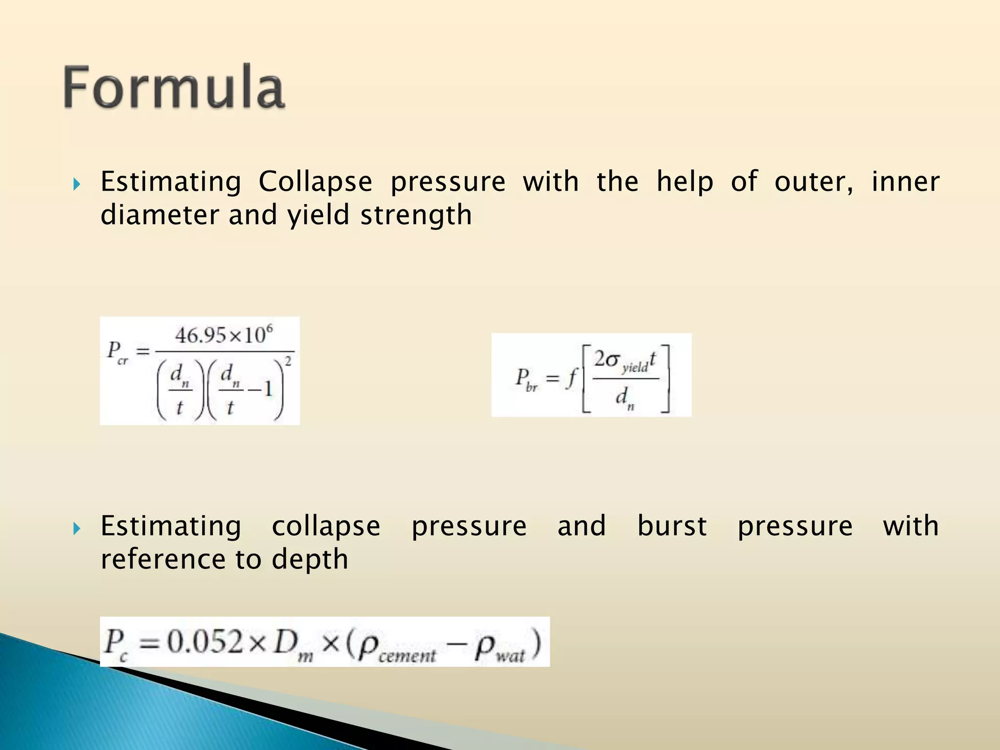
SlideShare a Scribd company logo
Lecturer
Syed Nawaz
Free Lance NDT Inspector
Founder of Petroleum Universe
 Introduction
 Functions of Casing
 Casing Types
 Approach to Casing Design
 Numerical Zone
 Conclusion
 References
 Hussain.et.al in Fundamentals of Sustainable Drilling says
that if a tubular is less 4.5 inch of diameter then it is tubing.
The range of casing diameter is 4.5” to 36”
 Once the section of subsurface is drilled, it has to be cased
with steel pipe, which is said to be Casing
 The reason behind the circular shape of casing is even
distribution of pressure
 Casing constitute 20-30% of the total cost of the well.
 Casing is installed to prevent the following
problems:
◦ Faults
◦ High pressure formations
◦ Toxic materials
◦ Thief zones, etc
 To protect near surface unconsolidated formations
 Provide protection against shallow gas flows
 Seal off shallow water zones
 Prevent caving of weak formations
 Provide protection against shallow blowouts
 It will ensure that formations at the casing shoe will not
fracture at the high hydrostatic pressure which may
encountered at later stage.
 Is usually set in the transition zone below or above an
over-pressured zone
 To seal off a severe loss zone
 To isolate producing zones,
 To provide reservoir fluid control
 To permit selective production in multizone production
 To isolate lost circulation or abnormally pressured zone
 It prevents cross channeling between two or more subsurface
fluid bearing layers
 To provide structural support for the wellhead and BOPs
 Note: Casing, Tubing, Drill Pipe must all confirm to API series
5 “Tubular Goods” including API Spec, ISO Specifications, etc
 Stove Casing
 Conductor Casing
 Surface Casing
 Intermediate Casing
 Production Casing
 Liner Casing
 These are marine conductor or foundation pile for offshore
drilling
 It is run to prevent washout of near surface unconsolidated
formations, to provide a circulation system
 This pipe does not carry any weight from the wellhead
equipment and can be driven into the ground or seabed
 The normal size for a stove pipe ranges from 26 in to 42 in
 Largest diameter
 Protect near surface unconsolidated formations, seal off
shallow water zones
 Size vary from 16 inch to 48 inch
 Conductor pipe is always cemented up-to the surface.
 Prevent caving of weak formations at shallow depths
 Shallow blowouts
 Depth of surface casing depends on aquifers and well head
pressure
 Diameter range is 18.625 to 20 inch in North Sea Operations
and casing size in middle east is usually 13.375
 Usually set in the transition zone below or above an over-
pressured zone
 Mainly design to overcome the problems like caving shale,
thief zones, mobile salt zones
 It ranges from 7.625 to 13.375 but no specific range of
length
 Last casing placed at the top of pay zone.
 Isolate producing zone
 Range is of 4.5, 5, 7 inches in O.D
 Do not reach the surface
 Mounted on liner hangers installed to previous casing string
(Intermediate Casing).
 In liner completions both the liner and the intermediate
casing act as the production string.
 The design criteria for liner is usually the ability to withstand
the maximum expected collapse pressure
 Design process
◦ Selection of Casing Sizes
◦ Selection of setting depths
◦ Definition of design properties
 Design properties
◦ Collapse pressure
◦ Burst pressure
◦ Yield strength: tensile and compressive
◦ Biaxial loading consideration
◦ Effect of Bending
 Design procedure
◦ Collapse pressure calculation
◦ Burst pressure calculation
◦ Tensile/ compressive strength calculation
 Safety factor
 Collapse
◦ Minimum external pressure required for pipe collapse (no
internal pressure or loads)
 Based on diameters and thickness there are 4
different types of collapse pressure
 The API bulletin 5C3 3 reports four formulas for
calculating the collapse resistance of tubular goods
and they are as follows:
◦ Elastic Collapse Pressure
◦ Transition Collapse Pressure
◦ Plastic Collapse Pressure
◦ Yield Strength Collapse Pressure
◦ Yield Strength (x<15.545)
◦ Plastic (15.545 < x < 26.025)
◦ Transition (26.025 < x < 39.9)
◦ Elastic (x > 39.912)
 Under field conditions, a given casing section
will be under the combined action of external
and internal pressure and axial load due to its
own weight
 Minimum internal pressure at
which pipe permanently deformed
(pipe is to no or less external
pressure or axial loads)
 API Burst is given as
 Lame equation is also used for
burst pressure
 Wall-thickness correction factor
0.875 for standard API tubulars
when a 12.5% wall-thickness
tolerance is specified.
 The ability of a metal to tolerate gradual progressive force
without any permanent damage or deformation.
 Classified into 2 pressures or loading: Axial Load and
Compressive Load
 Applying force on a structure directly along the structure axis
 API Design Factors Forces Range (Globally
used)
Collapse 1.0-1.125 (1.125)
Tension 1.0-2.0 (1.8)
Burst 1.0-1.33 (1.1)
Triaxial 1.25
 Casing Size
 Connections
 Weight
 Grade
 Length
 The OD is recognized as the size of Casing.
 The size of casing vary from 4.5” to 36”
 Drift Diameter: allowable diameter for next coming tool
 Breaking out the sequence then factors are to be estimated
such as
◦ Connections
◦ Mud weight
◦ Cementing
◦ Dogleg severity
 Pipe weight is usually expressed as weight per unit length in
lb/ft.
Weight Outer
dia
Inner
dia
Wall
thickness
Drift
dia
lb/ft in in in in
53.5=1658 9.625 8.535 0.545 8.379
47= 1457 9.625 8.681 0.472 8.525
43.5 =1348 9.625 8.755 0.435 8.599
40 = 1240 9.625 8.835 0.395 8.679
31
 The steel grade of the casing relates to the tensile strength of
the steel from which the casing is made
 Grade is a dependent property (Chemical Composition,
Mechanical Properties)
 The steel grade is expressed as a code which consists of a
letter and a number
 API Casing length ranges
 Most commonly used are R-2
Ranges Ranges of
Length (ft)
Average Length
(ft)
R-1 16-25 22
R-2 25-34 31
R-3 >34 42
 API provides 4 types of Casing connectors:
◦ CSG short round threads and couplings
◦ LCSG long round threads and couplings
◦ BCSG buttress threads and couplings
◦ XCSG extreme line threads
 CSG and LCSG combined are called API 8-
Round threads
 An intermediate section of 17.5 size was planned to be drilled at a
depth of 14,000 ft. A 13 3/8 OD casing is to be set and cemented in
this section. There are four casing types available in stocks which
are shown in Table below. Maximum burst pressure has to be
assumed when casing is full of 15.8 ppg cement slurry and fluid in
the annulus is water. In addition, maximum collapse pressure has to
be assumed when casing is full of fresh water and annulus is full of
15.8 ppg cement slurry. Safety factor for burst and collapse was
designed to be 1.18 and 1.15 respectively. Design a casing that
should be used in this section.
Depth of the casing shoe = 14,000 ft
Density of cement slurry 15.8 ppg
Density of fresh water = 8.34 ppg
Collapse safety factor = 1.15
Burst safety factor = 1.18
 Estimate the collapse and burst pressure for the available
casing sizes along with safety factor
 Then estimate collapse and burst pressure of required depth
without safety factor
 Based on magnitude select the casing
 Estimating Collapse pressure with the help of outer, inner
diameter and yield strength
 Estimating collapse pressure and burst pressure with
reference to depth
 For ID 12.031 inch
= 0.052 X 14000 X (15.8 – 8.34)
= 5430.88 psi
= 0.052 X 14000 X (15.8 – 8.34)
= 5430.88 psi
 The collapse pressure with safety factor is 5740 and burst
pressure is 5961 and the calculated magnitude is 5430.88
which lies between the above values. Thus 12.031 inch ID
casing is best.
 Hussain Rabia “Well Engineering and Construction”
 Hussain Rabia “Oil Well Drilling Engineering Principles and Practice”
 Hussain and Majid “Fundamental of Sustainable Drilling”
 “Formulas and Calculations for Drilling Operations” by G.James
 “Formulas and Calculations for Drilling, Production and Workover” by
Lapeyrouse
 Working Guide to Drilling Equipments and Operations by Williams Lyons
 Drilling Engineering Workbook by Baker Hughes
 “Drilling Engineering Technology” by Nediljka Gaurina Medimurec University
of Zagreb
 Advanced Oil Well Drilling Engineering by Mitchell
 Petroleum Well Construction Directional Drilling by Halliburton
 Adam.et.al “Applied Drilling Engineering”
 Drilling Engineering A complete well planning Aprroach by Neal Adam
 Petroleum Engineering Handbook by Warner Jr.
 Practical Field Reports I can’t mentioned their names
https://bit.ly/3ibtqZt
https://www.facebook.com/Petroleum-Universe-
575251903155462/?modal=admin_todo_tour
https://www.linkedin.com/company/67110978/ad
min/
https://www.slideshare.net/SYEDNAWAZ4/edit_my_
uploads

More Related Content

What's hot

BIT HYDRAULICS ANALYSIS FOR EFFICIENT HOLE CLEANING
BIT HYDRAULICS ANALYSIS FOR EFFICIENT HOLE CLEANINGBIT HYDRAULICS ANALYSIS FOR EFFICIENT HOLE CLEANING
BIT HYDRAULICS ANALYSIS FOR EFFICIENT HOLE CLEANING
Mahmood Ajabbar
 
Well control
Well controlWell control
Well control
Saba Saif
 
Drilling Fluid Circulation Systems
Drilling Fluid Circulation SystemsDrilling Fluid Circulation Systems
Drilling Fluid Circulation Systems
AFATous
 

What's hot (20)

Drilling Problems.pdf
Drilling Problems.pdfDrilling Problems.pdf
Drilling Problems.pdf
 
Casing
CasingCasing
Casing
 
Completion equipment packer part #1
Completion equipment packer part #1Completion equipment packer part #1
Completion equipment packer part #1
 
Introduction to directional drilling and its applications
Introduction to directional drilling and its applicationsIntroduction to directional drilling and its applications
Introduction to directional drilling and its applications
 
Stuck pipe
Stuck pipeStuck pipe
Stuck pipe
 
Directional Drilling
Directional DrillingDirectional Drilling
Directional Drilling
 
Drilling Engineering - Directional Drilling
Drilling Engineering - Directional DrillingDrilling Engineering - Directional Drilling
Drilling Engineering - Directional Drilling
 
Kick t1
Kick t1Kick t1
Kick t1
 
Drilling fluid
Drilling fluidDrilling fluid
Drilling fluid
 
Basic Well Control
Basic Well ControlBasic Well Control
Basic Well Control
 
BIT HYDRAULICS ANALYSIS FOR EFFICIENT HOLE CLEANING
BIT HYDRAULICS ANALYSIS FOR EFFICIENT HOLE CLEANINGBIT HYDRAULICS ANALYSIS FOR EFFICIENT HOLE CLEANING
BIT HYDRAULICS ANALYSIS FOR EFFICIENT HOLE CLEANING
 
Drilling fluids
Drilling fluidsDrilling fluids
Drilling fluids
 
introduction to completions and workovers (2)
introduction to completions and workovers (2)introduction to completions and workovers (2)
introduction to completions and workovers (2)
 
Petroleum Production Engineering - Perforation
Petroleum Production Engineering - PerforationPetroleum Production Engineering - Perforation
Petroleum Production Engineering - Perforation
 
Well control during drilling operations
Well control during drilling operationsWell control during drilling operations
Well control during drilling operations
 
Well control
Well controlWell control
Well control
 
Well control intro presentation
Well control intro presentationWell control intro presentation
Well control intro presentation
 
Intro to oil well drilling ops pt 1
Intro to oil well drilling ops pt 1Intro to oil well drilling ops pt 1
Intro to oil well drilling ops pt 1
 
Water Base Muds
Water Base MudsWater Base Muds
Water Base Muds
 
Drilling Fluid Circulation Systems
Drilling Fluid Circulation SystemsDrilling Fluid Circulation Systems
Drilling Fluid Circulation Systems
 

Similar to Casing design

casing types casing seating depth and casing design
casing types casing seating depth and casing designcasing types casing seating depth and casing design
casing types casing seating depth and casing design
ssuser2e4adf
 
Q922+de2+l06 v1
Q922+de2+l06 v1Q922+de2+l06 v1
Q922+de2+l06 v1
AFATous
 

Similar to Casing design (20)

Presentation 6 casing design
Presentation 6 casing designPresentation 6 casing design
Presentation 6 casing design
 
Casing_Design(1).ppt
Casing_Design(1).pptCasing_Design(1).ppt
Casing_Design(1).ppt
 
FL AWWA Steel Pipelines_0.pdf
FL AWWA Steel Pipelines_0.pdfFL AWWA Steel Pipelines_0.pdf
FL AWWA Steel Pipelines_0.pdf
 
production casing design considerations
production casing design considerationsproduction casing design considerations
production casing design considerations
 
Rehab Solutions for Today's Infrastructure
Rehab Solutions for Today's InfrastructureRehab Solutions for Today's Infrastructure
Rehab Solutions for Today's Infrastructure
 
casing types casing seating depth and casing design
casing types casing seating depth and casing designcasing types casing seating depth and casing design
casing types casing seating depth and casing design
 
Contech Slotted Drain for Commercial Markets
Contech Slotted Drain for Commercial MarketsContech Slotted Drain for Commercial Markets
Contech Slotted Drain for Commercial Markets
 
3440551.ppt
3440551.ppt3440551.ppt
3440551.ppt
 
Casing Seat depth and Basic casing design lecture 4.pdf
Casing Seat depth and Basic casing design  lecture 4.pdfCasing Seat depth and Basic casing design  lecture 4.pdf
Casing Seat depth and Basic casing design lecture 4.pdf
 
Stress analysis review and theory background.pptx
Stress analysis review and theory background.pptxStress analysis review and theory background.pptx
Stress analysis review and theory background.pptx
 
Q922+de2+l06 v1
Q922+de2+l06 v1Q922+de2+l06 v1
Q922+de2+l06 v1
 
Casing Design | Tubing | Well Control | Drilling | Gaurav Singh Rajput
Casing Design | Tubing | Well Control | Drilling | Gaurav Singh RajputCasing Design | Tubing | Well Control | Drilling | Gaurav Singh Rajput
Casing Design | Tubing | Well Control | Drilling | Gaurav Singh Rajput
 
Fluid conductors: Design and selection criteria
Fluid conductors: Design and selection criteriaFluid conductors: Design and selection criteria
Fluid conductors: Design and selection criteria
 
Calulation of deflection and crack width according to is 456 2000
Calulation of deflection and crack width according to is 456 2000Calulation of deflection and crack width according to is 456 2000
Calulation of deflection and crack width according to is 456 2000
 
Design of Sprinkler System and CO2 Total Flooding System of Given Plan I Gaur...
Design of Sprinkler System and CO2 Total Flooding System of Given Plan I Gaur...Design of Sprinkler System and CO2 Total Flooding System of Given Plan I Gaur...
Design of Sprinkler System and CO2 Total Flooding System of Given Plan I Gaur...
 
Pressure_vessel_design_slides.pdf
Pressure_vessel_design_slides.pdfPressure_vessel_design_slides.pdf
Pressure_vessel_design_slides.pdf
 
4. Mechanical design of pressure vessels_slides.pdf
4. Mechanical design of pressure vessels_slides.pdf4. Mechanical design of pressure vessels_slides.pdf
4. Mechanical design of pressure vessels_slides.pdf
 
Casing Design 1.ppt
Casing Design 1.pptCasing Design 1.ppt
Casing Design 1.ppt
 
Presentation on Piping Familiarization.ppt
Presentation on Piping Familiarization.pptPresentation on Piping Familiarization.ppt
Presentation on Piping Familiarization.ppt
 
Drilling Mannual
Drilling MannualDrilling Mannual
Drilling Mannual
 

More from SYED NAWAZ

More from SYED NAWAZ (20)

Mud loss or lost circulation
Mud loss or lost circulationMud loss or lost circulation
Mud loss or lost circulation
 
Play types and related petroleum systems
Play types and related petroleum systemsPlay types and related petroleum systems
Play types and related petroleum systems
 
Density of a fluid
Density of a fluidDensity of a fluid
Density of a fluid
 
Field development plan, rate of production,
Field development plan, rate of production,Field development plan, rate of production,
Field development plan, rate of production,
 
Gate petroleum engineering analysis
Gate petroleum engineering analysisGate petroleum engineering analysis
Gate petroleum engineering analysis
 
Overview of drilling
Overview of drillingOverview of drilling
Overview of drilling
 
Surface Tension and Interfacial Tension Formula, Units and Problem
Surface Tension and Interfacial Tension Formula, Units and ProblemSurface Tension and Interfacial Tension Formula, Units and Problem
Surface Tension and Interfacial Tension Formula, Units and Problem
 
Surface and interfacial tension
Surface and interfacial tensionSurface and interfacial tension
Surface and interfacial tension
 
Petrophysical Properties of Reservoir
Petrophysical Properties of ReservoirPetrophysical Properties of Reservoir
Petrophysical Properties of Reservoir
 
Saturation
SaturationSaturation
Saturation
 
Oil formation volume factor
Oil formation volume factor Oil formation volume factor
Oil formation volume factor
 
gas formation volume factor derivation
gas formation volume factor derivationgas formation volume factor derivation
gas formation volume factor derivation
 
Reynolds number
Reynolds numberReynolds number
Reynolds number
 
Gate 2017 pressure difference
Gate 2017 pressure differenceGate 2017 pressure difference
Gate 2017 pressure difference
 
Formation damage evaluation
Formation damage evaluationFormation damage evaluation
Formation damage evaluation
 
Unit conversion
Unit conversionUnit conversion
Unit conversion
 
Skin factor determination
Skin factor determinationSkin factor determination
Skin factor determination
 
Recovery factor and total time
Recovery factor and total timeRecovery factor and total time
Recovery factor and total time
 
Pump input
Pump inputPump input
Pump input
 
Porosity with grain volume
Porosity with grain volumePorosity with grain volume
Porosity with grain volume
 

Recently uploaded

Fruit shop management system project report.pdf
Fruit shop management system project report.pdfFruit shop management system project report.pdf
Fruit shop management system project report.pdf
Kamal Acharya
 
Digital Signal Processing Lecture notes n.pdf
Digital Signal Processing Lecture notes n.pdfDigital Signal Processing Lecture notes n.pdf
Digital Signal Processing Lecture notes n.pdf
AbrahamGadissa
 
LIGA(E)11111111111111111111111111111111111111111.ppt
LIGA(E)11111111111111111111111111111111111111111.pptLIGA(E)11111111111111111111111111111111111111111.ppt
LIGA(E)11111111111111111111111111111111111111111.ppt
ssuser9bd3ba
 
Automobile Management System Project Report.pdf
Automobile Management System Project Report.pdfAutomobile Management System Project Report.pdf
Automobile Management System Project Report.pdf
Kamal Acharya
 

Recently uploaded (20)

WATER CRISIS and its solutions-pptx 1234
WATER CRISIS and its solutions-pptx 1234WATER CRISIS and its solutions-pptx 1234
WATER CRISIS and its solutions-pptx 1234
 
Fruit shop management system project report.pdf
Fruit shop management system project report.pdfFruit shop management system project report.pdf
Fruit shop management system project report.pdf
 
NO1 Pandit Amil Baba In Bahawalpur, Sargodha, Sialkot, Sheikhupura, Rahim Yar...
NO1 Pandit Amil Baba In Bahawalpur, Sargodha, Sialkot, Sheikhupura, Rahim Yar...NO1 Pandit Amil Baba In Bahawalpur, Sargodha, Sialkot, Sheikhupura, Rahim Yar...
NO1 Pandit Amil Baba In Bahawalpur, Sargodha, Sialkot, Sheikhupura, Rahim Yar...
 
Digital Signal Processing Lecture notes n.pdf
Digital Signal Processing Lecture notes n.pdfDigital Signal Processing Lecture notes n.pdf
Digital Signal Processing Lecture notes n.pdf
 
Courier management system project report.pdf
Courier management system project report.pdfCourier management system project report.pdf
Courier management system project report.pdf
 
Cloud-Computing_CSE311_Computer-Networking CSE GUB BD - Shahidul.pptx
Cloud-Computing_CSE311_Computer-Networking CSE GUB BD - Shahidul.pptxCloud-Computing_CSE311_Computer-Networking CSE GUB BD - Shahidul.pptx
Cloud-Computing_CSE311_Computer-Networking CSE GUB BD - Shahidul.pptx
 
Online resume builder management system project report.pdf
Online resume builder management system project report.pdfOnline resume builder management system project report.pdf
Online resume builder management system project report.pdf
 
HYDROPOWER - Hydroelectric power generation
HYDROPOWER - Hydroelectric power generationHYDROPOWER - Hydroelectric power generation
HYDROPOWER - Hydroelectric power generation
 
ENERGY STORAGE DEVICES INTRODUCTION UNIT-I
ENERGY STORAGE DEVICES  INTRODUCTION UNIT-IENERGY STORAGE DEVICES  INTRODUCTION UNIT-I
ENERGY STORAGE DEVICES INTRODUCTION UNIT-I
 
LIGA(E)11111111111111111111111111111111111111111.ppt
LIGA(E)11111111111111111111111111111111111111111.pptLIGA(E)11111111111111111111111111111111111111111.ppt
LIGA(E)11111111111111111111111111111111111111111.ppt
 
Vaccine management system project report documentation..pdf
Vaccine management system project report documentation..pdfVaccine management system project report documentation..pdf
Vaccine management system project report documentation..pdf
 
Democratizing Fuzzing at Scale by Abhishek Arya
Democratizing Fuzzing at Scale by Abhishek AryaDemocratizing Fuzzing at Scale by Abhishek Arya
Democratizing Fuzzing at Scale by Abhishek Arya
 
Explosives Industry manufacturing process.pdf
Explosives Industry manufacturing process.pdfExplosives Industry manufacturing process.pdf
Explosives Industry manufacturing process.pdf
 
CME397 Surface Engineering- Professional Elective
CME397 Surface Engineering- Professional ElectiveCME397 Surface Engineering- Professional Elective
CME397 Surface Engineering- Professional Elective
 
A CASE STUDY ON ONLINE TICKET BOOKING SYSTEM PROJECT.pdf
A CASE STUDY ON ONLINE TICKET BOOKING SYSTEM PROJECT.pdfA CASE STUDY ON ONLINE TICKET BOOKING SYSTEM PROJECT.pdf
A CASE STUDY ON ONLINE TICKET BOOKING SYSTEM PROJECT.pdf
 
Automobile Management System Project Report.pdf
Automobile Management System Project Report.pdfAutomobile Management System Project Report.pdf
Automobile Management System Project Report.pdf
 
Construction method of steel structure space frame .pptx
Construction method of steel structure space frame .pptxConstruction method of steel structure space frame .pptx
Construction method of steel structure space frame .pptx
 
weather web application report.pdf
weather web application report.pdfweather web application report.pdf
weather web application report.pdf
 
Natalia Rutkowska - BIM School Course in Kraków
Natalia Rutkowska - BIM School Course in KrakówNatalia Rutkowska - BIM School Course in Kraków
Natalia Rutkowska - BIM School Course in Kraków
 
The Benefits and Techniques of Trenchless Pipe Repair.pdf
The Benefits and Techniques of Trenchless Pipe Repair.pdfThe Benefits and Techniques of Trenchless Pipe Repair.pdf
The Benefits and Techniques of Trenchless Pipe Repair.pdf
 

Casing design

  • 1. Lecturer Syed Nawaz Free Lance NDT Inspector Founder of Petroleum Universe
  • 2.  Introduction  Functions of Casing  Casing Types  Approach to Casing Design  Numerical Zone  Conclusion  References
  • 3.  Hussain.et.al in Fundamentals of Sustainable Drilling says that if a tubular is less 4.5 inch of diameter then it is tubing. The range of casing diameter is 4.5” to 36”  Once the section of subsurface is drilled, it has to be cased with steel pipe, which is said to be Casing  The reason behind the circular shape of casing is even distribution of pressure  Casing constitute 20-30% of the total cost of the well.
  • 4.  Casing is installed to prevent the following problems: ◦ Faults ◦ High pressure formations ◦ Toxic materials ◦ Thief zones, etc
  • 5.  To protect near surface unconsolidated formations  Provide protection against shallow gas flows  Seal off shallow water zones  Prevent caving of weak formations  Provide protection against shallow blowouts  It will ensure that formations at the casing shoe will not fracture at the high hydrostatic pressure which may encountered at later stage.  Is usually set in the transition zone below or above an over-pressured zone  To seal off a severe loss zone  To isolate producing zones,  To provide reservoir fluid control  To permit selective production in multizone production  To isolate lost circulation or abnormally pressured zone
  • 6.  It prevents cross channeling between two or more subsurface fluid bearing layers  To provide structural support for the wellhead and BOPs  Note: Casing, Tubing, Drill Pipe must all confirm to API series 5 “Tubular Goods” including API Spec, ISO Specifications, etc
  • 7.  Stove Casing  Conductor Casing  Surface Casing  Intermediate Casing  Production Casing  Liner Casing
  • 8.  These are marine conductor or foundation pile for offshore drilling  It is run to prevent washout of near surface unconsolidated formations, to provide a circulation system  This pipe does not carry any weight from the wellhead equipment and can be driven into the ground or seabed  The normal size for a stove pipe ranges from 26 in to 42 in
  • 9.  Largest diameter  Protect near surface unconsolidated formations, seal off shallow water zones  Size vary from 16 inch to 48 inch  Conductor pipe is always cemented up-to the surface.
  • 10.  Prevent caving of weak formations at shallow depths  Shallow blowouts  Depth of surface casing depends on aquifers and well head pressure  Diameter range is 18.625 to 20 inch in North Sea Operations and casing size in middle east is usually 13.375
  • 11.  Usually set in the transition zone below or above an over- pressured zone  Mainly design to overcome the problems like caving shale, thief zones, mobile salt zones  It ranges from 7.625 to 13.375 but no specific range of length
  • 12.  Last casing placed at the top of pay zone.  Isolate producing zone  Range is of 4.5, 5, 7 inches in O.D
  • 13.  Do not reach the surface  Mounted on liner hangers installed to previous casing string (Intermediate Casing).  In liner completions both the liner and the intermediate casing act as the production string.  The design criteria for liner is usually the ability to withstand the maximum expected collapse pressure
  • 14.
  • 15.
  • 16.  Design process ◦ Selection of Casing Sizes ◦ Selection of setting depths ◦ Definition of design properties  Design properties ◦ Collapse pressure ◦ Burst pressure ◦ Yield strength: tensile and compressive ◦ Biaxial loading consideration ◦ Effect of Bending  Design procedure ◦ Collapse pressure calculation ◦ Burst pressure calculation ◦ Tensile/ compressive strength calculation  Safety factor
  • 17.
  • 18.
  • 19.  Collapse ◦ Minimum external pressure required for pipe collapse (no internal pressure or loads)
  • 20.  Based on diameters and thickness there are 4 different types of collapse pressure  The API bulletin 5C3 3 reports four formulas for calculating the collapse resistance of tubular goods and they are as follows: ◦ Elastic Collapse Pressure ◦ Transition Collapse Pressure ◦ Plastic Collapse Pressure ◦ Yield Strength Collapse Pressure
  • 21. ◦ Yield Strength (x<15.545) ◦ Plastic (15.545 < x < 26.025) ◦ Transition (26.025 < x < 39.9) ◦ Elastic (x > 39.912)
  • 22.  Under field conditions, a given casing section will be under the combined action of external and internal pressure and axial load due to its own weight
  • 23.  Minimum internal pressure at which pipe permanently deformed (pipe is to no or less external pressure or axial loads)  API Burst is given as  Lame equation is also used for burst pressure  Wall-thickness correction factor 0.875 for standard API tubulars when a 12.5% wall-thickness tolerance is specified.
  • 24.
  • 25.  The ability of a metal to tolerate gradual progressive force without any permanent damage or deformation.  Classified into 2 pressures or loading: Axial Load and Compressive Load  Applying force on a structure directly along the structure axis
  • 26.
  • 27.  API Design Factors Forces Range (Globally used) Collapse 1.0-1.125 (1.125) Tension 1.0-2.0 (1.8) Burst 1.0-1.33 (1.1) Triaxial 1.25
  • 28.  Casing Size  Connections  Weight  Grade  Length
  • 29.  The OD is recognized as the size of Casing.  The size of casing vary from 4.5” to 36”  Drift Diameter: allowable diameter for next coming tool  Breaking out the sequence then factors are to be estimated such as ◦ Connections ◦ Mud weight ◦ Cementing ◦ Dogleg severity
  • 30.
  • 31.  Pipe weight is usually expressed as weight per unit length in lb/ft. Weight Outer dia Inner dia Wall thickness Drift dia lb/ft in in in in 53.5=1658 9.625 8.535 0.545 8.379 47= 1457 9.625 8.681 0.472 8.525 43.5 =1348 9.625 8.755 0.435 8.599 40 = 1240 9.625 8.835 0.395 8.679 31
  • 32.  The steel grade of the casing relates to the tensile strength of the steel from which the casing is made  Grade is a dependent property (Chemical Composition, Mechanical Properties)  The steel grade is expressed as a code which consists of a letter and a number
  • 33.  API Casing length ranges  Most commonly used are R-2 Ranges Ranges of Length (ft) Average Length (ft) R-1 16-25 22 R-2 25-34 31 R-3 >34 42
  • 34.
  • 35.  API provides 4 types of Casing connectors: ◦ CSG short round threads and couplings ◦ LCSG long round threads and couplings ◦ BCSG buttress threads and couplings ◦ XCSG extreme line threads  CSG and LCSG combined are called API 8- Round threads
  • 36.  An intermediate section of 17.5 size was planned to be drilled at a depth of 14,000 ft. A 13 3/8 OD casing is to be set and cemented in this section. There are four casing types available in stocks which are shown in Table below. Maximum burst pressure has to be assumed when casing is full of 15.8 ppg cement slurry and fluid in the annulus is water. In addition, maximum collapse pressure has to be assumed when casing is full of fresh water and annulus is full of 15.8 ppg cement slurry. Safety factor for burst and collapse was designed to be 1.18 and 1.15 respectively. Design a casing that should be used in this section.
  • 37. Depth of the casing shoe = 14,000 ft Density of cement slurry 15.8 ppg Density of fresh water = 8.34 ppg Collapse safety factor = 1.15 Burst safety factor = 1.18
  • 38.  Estimate the collapse and burst pressure for the available casing sizes along with safety factor  Then estimate collapse and burst pressure of required depth without safety factor  Based on magnitude select the casing
  • 39.  Estimating Collapse pressure with the help of outer, inner diameter and yield strength  Estimating collapse pressure and burst pressure with reference to depth
  • 40.  For ID 12.031 inch
  • 41.
  • 42. = 0.052 X 14000 X (15.8 – 8.34) = 5430.88 psi = 0.052 X 14000 X (15.8 – 8.34) = 5430.88 psi
  • 43.  The collapse pressure with safety factor is 5740 and burst pressure is 5961 and the calculated magnitude is 5430.88 which lies between the above values. Thus 12.031 inch ID casing is best.
  • 44.  Hussain Rabia “Well Engineering and Construction”  Hussain Rabia “Oil Well Drilling Engineering Principles and Practice”  Hussain and Majid “Fundamental of Sustainable Drilling”  “Formulas and Calculations for Drilling Operations” by G.James  “Formulas and Calculations for Drilling, Production and Workover” by Lapeyrouse  Working Guide to Drilling Equipments and Operations by Williams Lyons  Drilling Engineering Workbook by Baker Hughes  “Drilling Engineering Technology” by Nediljka Gaurina Medimurec University of Zagreb  Advanced Oil Well Drilling Engineering by Mitchell  Petroleum Well Construction Directional Drilling by Halliburton  Adam.et.al “Applied Drilling Engineering”  Drilling Engineering A complete well planning Aprroach by Neal Adam  Petroleum Engineering Handbook by Warner Jr.  Practical Field Reports I can’t mentioned their names