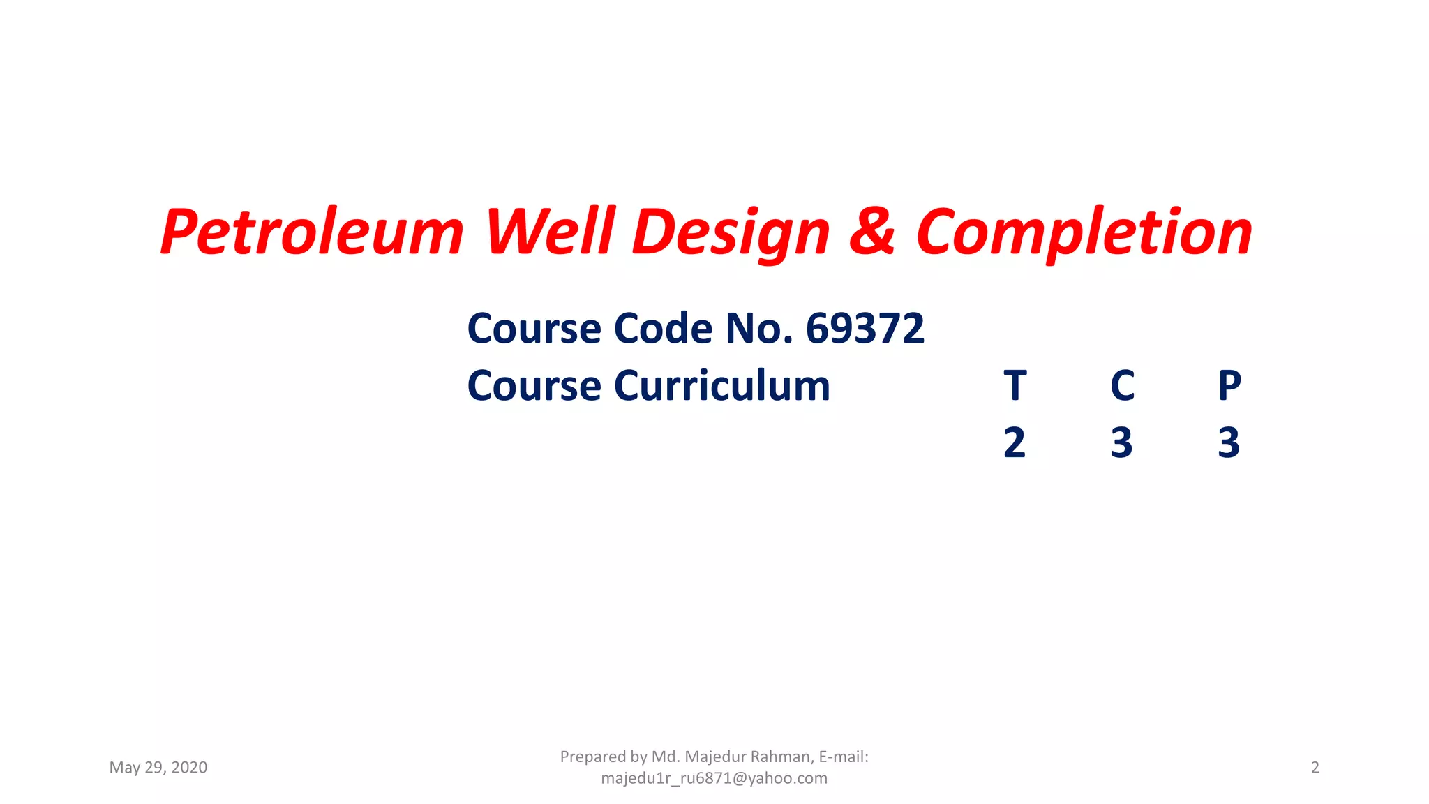
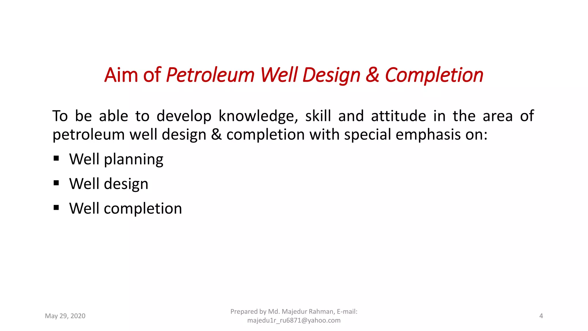
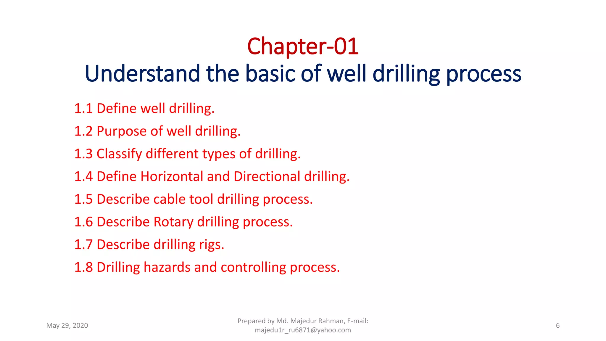
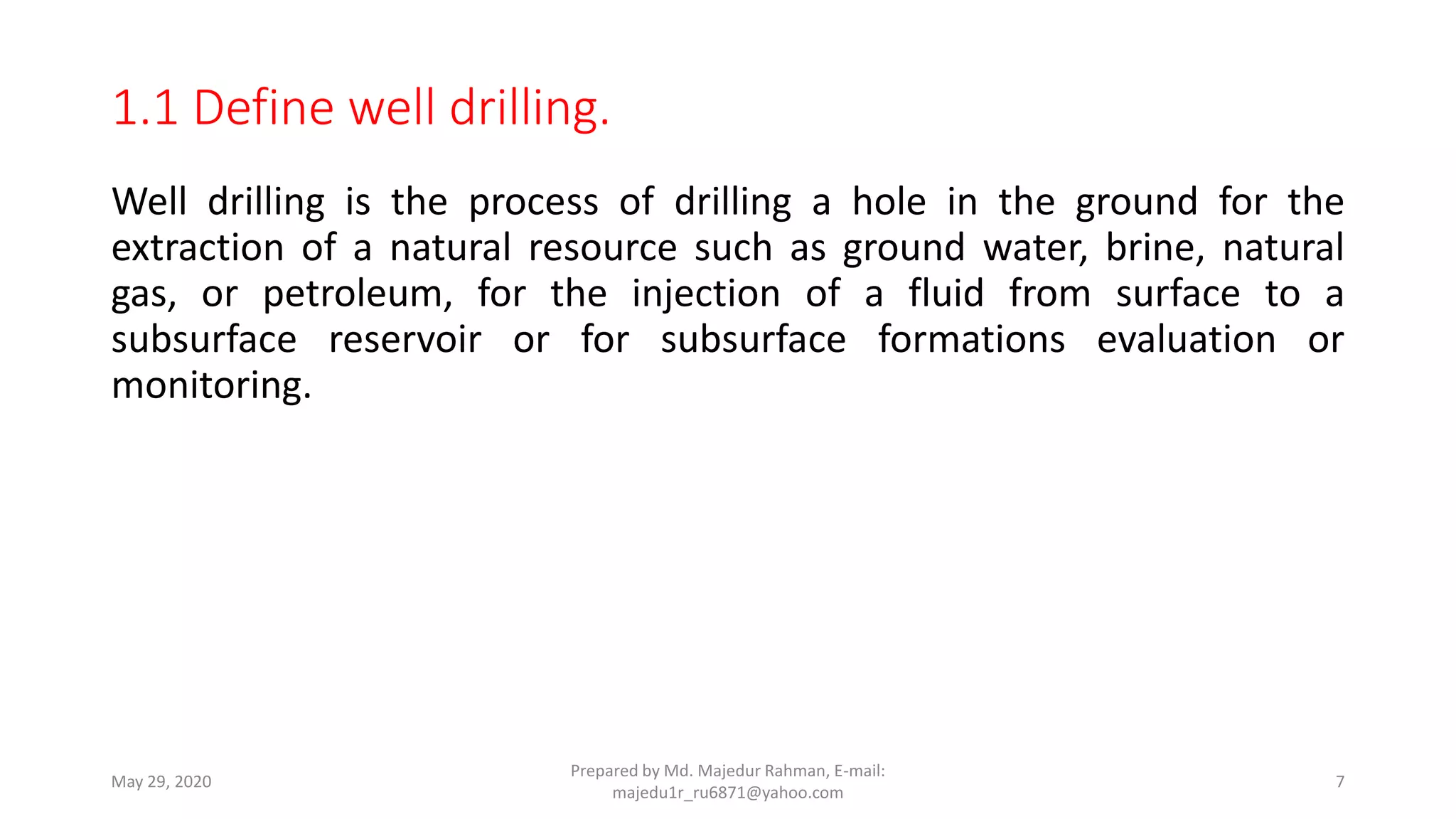
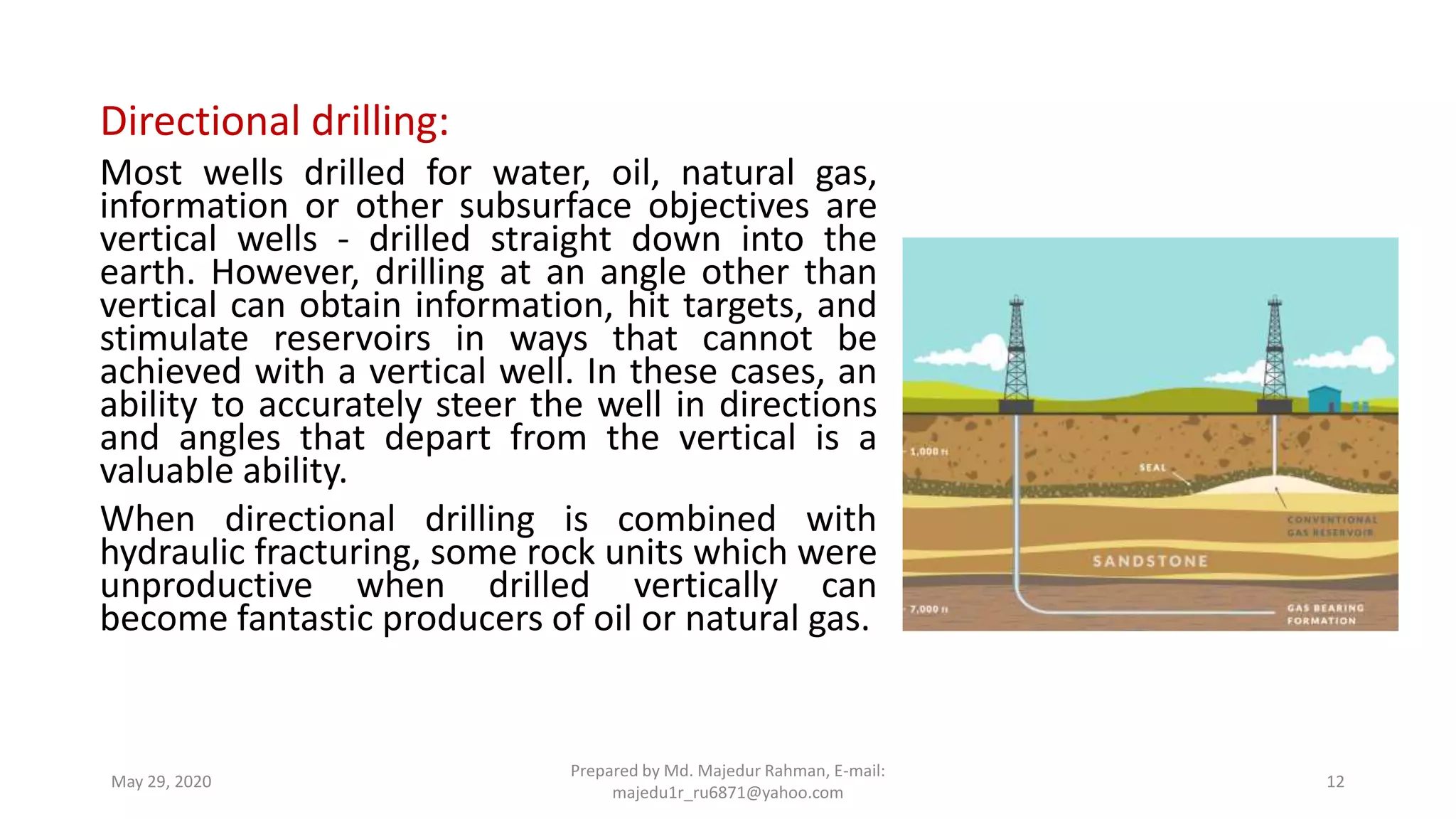
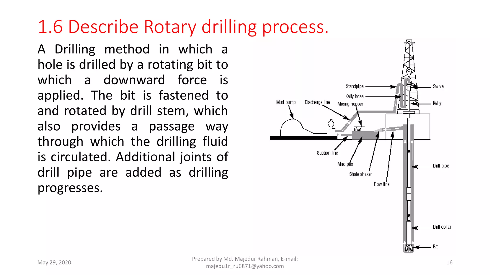
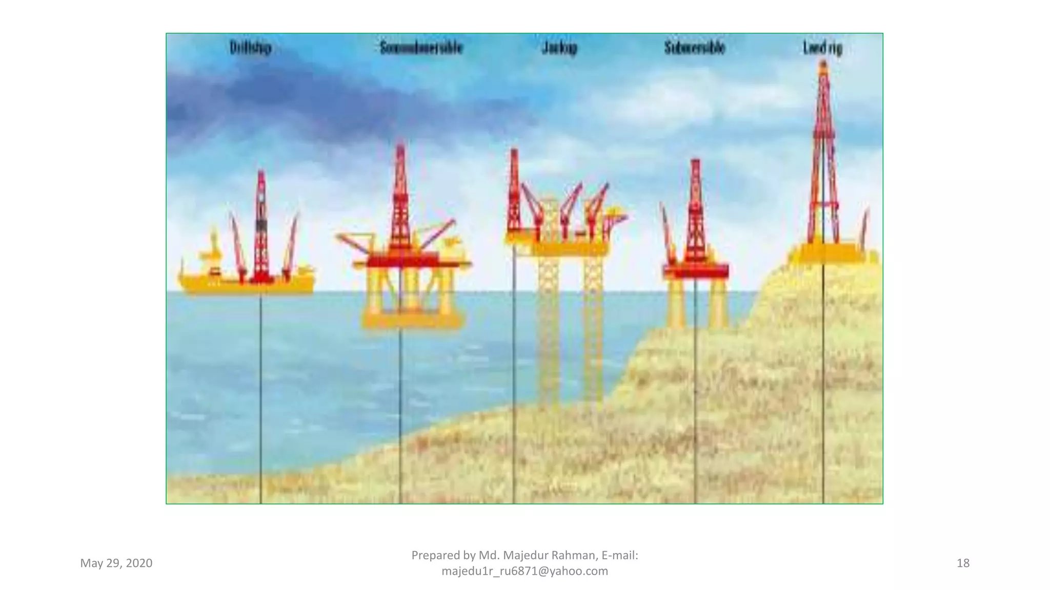
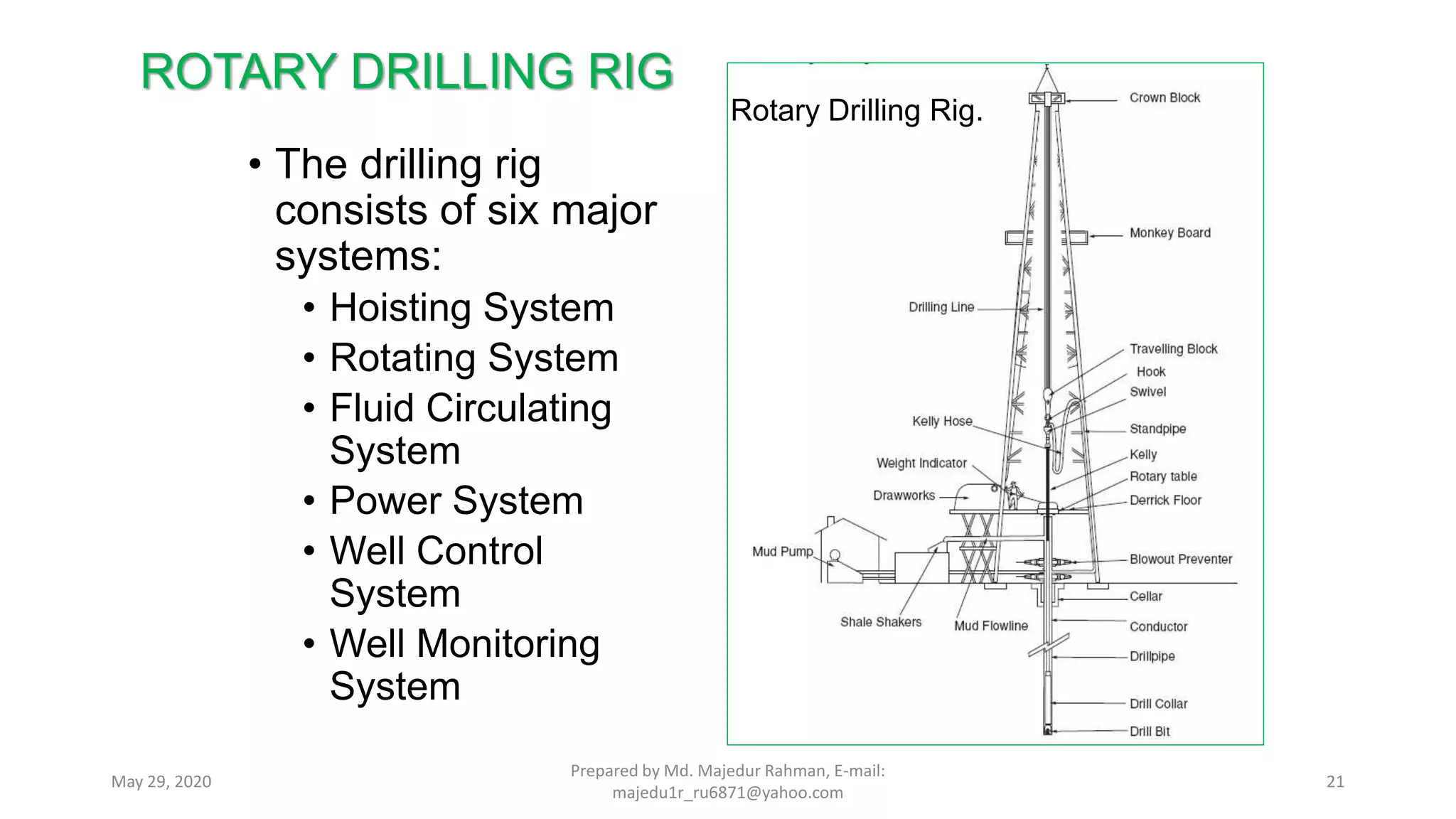
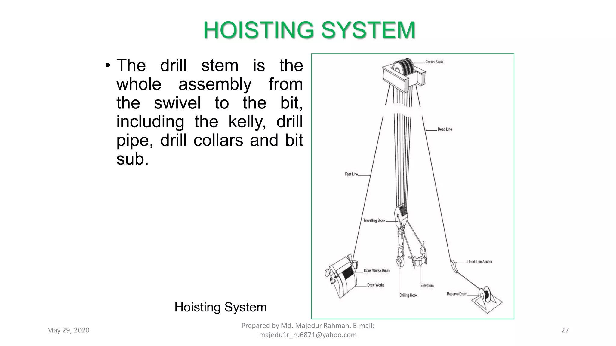
WELCOME TO THE STUDENTS
7th Semester (Mining)
Bogura Polytechnic Institute, Bogura.
Md. Majedur Rahman
B. Sc (Hon’s), M. Sc in Geology & Mining, RU
Instructor (Tech)
Mining and Mine Survey Technology
Bogura Polytechnic Institute, BOGURA.
Presented By
Prepared by Md. Majedur Rahman, E-mail: majedu1r_ru6871@yahoo.comMay 29, 2020 1
Petroleum Well Design & Completion
Course Code No. 69372
Course Curriculum T C P
2 3 3
Prepared by Md. Majedur Rahman, E-mail:
majedu1r_ru6871@yahoo.com
May 29, 2020 2
May 29, 2020
Prepared by Md. Majedur Rahman, E-mail:
majedu1r_ru6871@yahoo.com
3
Why we study Petroleum Well Design & Completion?
Aim of Petroleum Well Design & Completion
To be able to develop knowledge, skill and attitude in the area of
petroleum well design & completion with special emphasis on:
 Well planning
 Well design
 Well completion
May 29, 2020
Prepared by Md. Majedur Rahman, E-mail:
majedu1r_ru6871@yahoo.com
4
Short description of the course
• Well drilling process;
• Well planning;
• Well drilling design;
• Casing deign;
• Drilling bit design;
• Drilling fluid;
• Cementing; Coring;
• Well control and Blowout prevention;
• Well completion and testing.
May 29, 2020
Prepared by Md. Majedur Rahman, E-mail:
majedu1r_ru6871@yahoo.com
5
Chapter-01
Understand the basic of well drilling process
1.1 Define well drilling.
1.2 Purpose of well drilling.
1.3 Classify different types of drilling.
1.4 Define Horizontal and Directional drilling.
1.5 Describe cable tool drilling process.
1.6 Describe Rotary drilling process.
1.7 Describe drilling rigs.
1.8 Drilling hazards and controlling process.
Prepared by Md. Majedur Rahman, E-mail:
majedu1r_ru6871@yahoo.com
May 29, 2020 6
Well drilling is the process of drilling a hole in the ground for the
extraction of a natural resource such as ground water, brine, natural
gas, or petroleum, for the injection of a fluid from surface to a
subsurface reservoir or for subsurface formations evaluation or
monitoring.
May 29, 2020
Prepared by Md. Majedur Rahman, E-mail:
majedu1r_ru6871@yahoo.com
7
1.1 Define well drilling.
Drilling is an important method of prospecting subsurface rocks and ore
deposits. In drilling data are collected by direct penetration of subsurface
rocks by drill holes. The samples of rocks are obtained in the form of
cylindrical cores or rock fragments. The drilling holes provide the following
information’s.
• Size, shape and morphology of the ore body.
• Geological structures and number of lodes present.
• Nature of the host rocks.
• Composition and grade of the ore body.
• To produces oil and gas.
• To collect the sample for exploration well.
Prepared by Md. Majedur Rahman, E-mail:
majedu1r_ru6871@yahoo.com
May 29, 2020 8
1.2 Purpose of well drilling.
1.3 Classify different types of drilling.
There are a variety of drilling mechanisms which can be used to sink a
borehole into the ground. Each has its advantages and disadvantages, in
terms of depth to which it can drill, type of sample returned, the costs
involved and penetration rates achieved. There are two basic types of drills:
drills which produce rock chips, and drills which produce core samples.
• Auger drilling
• Percussion rotary air blast drilling (RAB)
• Air core drilling
• Cable tool drilling
• Reverse circulation (RC) drilling
• Diamond core drilling
• Hydraulic Rotary drilling
• Sonic (Vibratory) drilling
May 29, 2020
Prepared by Md. Majedur Rahman, E-mail:
majedu1r_ru6871@yahoo.com
9
1.4 Define Horizontal and Directional drilling.
Define Horizontal: Natural gas,
crude oil and geothermal drilling is
frequently performed using the
rotary drilling process. In the rotary
drilling process, a rotating drilling
head on a drill pipe bores into the
earth’s crust down to the crude oil,
natural gas or geothermal deposit.
May 29, 2020
Prepared by Md. Majedur Rahman, E-mail:
majedu1r_ru6871@yahoo.com
10
The application of horizontal drilling
• Directly following vertical drilling, the direction of the drilling head
can be changed to continue drilling “horizontally”. The exploration
and extraction of crude oil and natural gas deposits is increasingly
being realised by means of horizontal drilling, also in Germany.
• Horizontal drilling within the deposit allows oil and gas fields to be
developed with fewer bore holes. In combination with the fracking
technique (see hydraulic fracturing), additional crude oil or natural
gas can be extracted even from harder layers of rock.
May 29, 2020
Prepared by Md. Majedur Rahman, E-mail:
majedu1r_ru6871@yahoo.com
11
Directional drilling:
Most wells drilled for water, oil, natural gas,
information or other subsurface objectives are
vertical wells - drilled straight down into the
earth. However, drilling at an angle other than
vertical can obtain information, hit targets, and
stimulate reservoirs in ways that cannot be
achieved with a vertical well. In these cases, an
ability to accurately steer the well in directions
and angles that depart from the vertical is a
valuable ability.
When directional drilling is combined with
hydraulic fracturing, some rock units which were
unproductive when drilled vertically can
become fantastic producers of oil or natural gas.
May 29, 2020
Prepared by Md. Majedur Rahman, E-mail:
majedu1r_ru6871@yahoo.com
12
Why Drill Wells That Are Non-Vertical?
Directional and horizontal drilling have been used to reach targets beneath
adjacent lands, reduce the footprint of gas field development, increase the
length of the "pay zone" in a well, deliberately intersect fractures, construct
relief wells, and install utility service beneath lands where excavation is
impossible or extremely expensive.
Below is a list of six reasons for drilling non-vertical wells. They are
graphically illustrated by the six drawings on this page.
A) Hit targets that cannot be reached by vertical drilling.
B) Drain a broad area from a single drilling pad.
C) Increase the length of the "pay zone" within the target rock unit.
D) Improve the productivity of wells in a fractured reservoir.
E) Seal or relieve pressure in an "out-of-control" well.
F) Install underground utilities where excavation is not possible.
May 29, 2020
Prepared by Md. Majedur Rahman, E-mail:
majedu1r_ru6871@yahoo.com
13
1.5 Describe cable tool drilling process.
• A Drilling method in which a hole is drilled by dropping a sharply pointed
bit on the bottom of the hole. The bit is attached to a cable, and the cable
is repeatedly picked up and dropped as the hole is drilled.
• Cable-tool was the first method used to drill a bore hole and is still in use,
particularly for shallow oil or gas wells in the Appalachian Basin. The cable
refers to the manila hemp rope used to suspend the wooden rods and the
drilling tools in the earliest operations. The manila line and wooden rods
were eventually replaced by multiple-strand steel rope often called wire
line or wire rope.
• The cable (manila rope or wire line) pulls the string of tools up and down as
brought about by a spring pole or a walking beam at the surface. The
heavy bit has a blunt chisel end which cracks, chips and smashes the rock
by the repeated blows delivered in a measured or regular cadence.
May 29, 2020
Prepared by Md. Majedur Rahman, E-mail:
majedu1r_ru6871@yahoo.com
14
• Percussion drilling is another name for
cable-tool drilling. It refers to the
blows delivered to the rock by the bit.
May 29, 2020
Prepared by Md. Majedur Rahman, E-mail:
majedu1r_ru6871@yahoo.com
15
1.6 Describe Rotary drilling process.
A Drilling method in which a
hole is drilled by a rotating bit to
which a downward force is
applied. The bit is fastened to
and rotated by drill stem, which
also provides a passage way
through which the drilling fluid
is circulated. Additional joints of
drill pipe are added as drilling
progresses.
May 29, 2020
Prepared by Md. Majedur Rahman, E-mail:
majedu1r_ru6871@yahoo.com
16
ROTARY DRILLING RIG
• The main function of rotary drilling rig is to make hole.
• The moving of the rig from site to site depends on weight and size of
each rig component.
• Each unit assembly is limited in weight because of truck and highway
limitations on gross weight.
• Rotary drilling rigs must be disassembled into many components so
that weight limits are not exceeded.
May 29, 2020
Prepared by Md. Majedur Rahman, E-mail:
majedu1r_ru6871@yahoo.com
17
1.7 Describe drilling rigs.
May 29, 2020
Prepared by Md. Majedur Rahman, E-mail:
majedu1r_ru6871@yahoo.com
18
ROTARY DRILLING RIG
• Rotary rig design should:
Allow for rapid erection and take-down, and consist of
few pieces as possible.
Not require special cranes for assembly (rig-up) or
disassembly (tear-down).
Enable drill pipe to be run into the hole or pulled out
with minimum time wasted.
Provide the maximum amount of available power for
the circulating fluid to the bit.
Prepared by Md. Majedur Rahman, E-mail:
majedu1r_ru6871@yahoo.com
19May 29, 2020
ROTARY DRILLING RIG
• Many factors determine a rig’s portability:
Wheel-mounted rigs can be used for drilling to depths of
10,000 feet or more and for completion/workover service on
15,000-foot wells.
These rigs have self-erecting, telescoping masts; and the
mast, drawworks and engines are built on a trailer or self-
propelled unit.
Equipment such as mud pumps must be handled as
packages.
Therefore, efficient planning and design are necessary.
Prepared by Md. Majedur Rahman, E-mail:
majedu1r_ru6871@yahoo.com
20May 29, 2020
• The drilling rig
consists of six major
systems:
• Hoisting System
• Rotating System
• Fluid Circulating
System
• Power System
• Well Control
System
• Well Monitoring
System
ROTARY DRILLING RIG
Rotary Drilling Rig.
21May 29, 2020
Prepared by Md. Majedur Rahman, E-mail:
majedu1r_ru6871@yahoo.com
• RC Cyclone
• Gear Type Rotation Head
• Diverter System
• Hydraulic Wet Rotary Splitter, for
Reverse Circulation drilling
• Universal Hydraulic Tilt Splitter, for
Reverse Circulation drilling
• Blow Back System
• Hydraulic Hoses
• Hydraulic Mud Mixer
• Air-Operated Double Diaphragm Pumps
• Mud Tank
May 29, 2020
Prepared by Md. Majedur Rahman, E-mail:
majedu1r_ru6871@yahoo.com
22
Drill Rig Accessories
 Mud Mixer Spare Parts: Parker motor and impeller
 Left Hand and Right Hand Angle indicators
 Bit Basket
 Bit Sharpening System
 Automatic lubricator for the down the hole
hammer
 Whip Checks
 Thread locking compound Bakerlok
 Handled Oiler
 Rigging Hardware
 Fishing Tools
 Compressor air hoses
HOISTING SYSTEM
DERRICK
The function of a derrick is
to provide vertical
clearance to the raising
and lowering of drill string
into and out of borehole
Two type of Derricks
Standard Derricks - it is of
bolted construction and
assembled part by part
Mast – a portable derrick,
one capable of being
erected as a unit
Prepared by Md. Majedur Rahman, E-mail:
majedu1r_ru6871@yahoo.com
23May 29, 2020
CROWN BLOCK
The fixed set of pulleys
(called sheaves) located at
the top of the derrick or
mast over which the drilling
line is threaded.
TRAVELLING BLOCK
A pulley (sheave)
assembly that connects the
drilling line to the hook and
swivel
HOISTING SYSTEM
Prepared by Md. Majedur Rahman, E-mail:
majedu1r_ru6871@yahoo.com
24May 29, 2020
DRAWWORKS
 It is the control center
from which the driller
operates the rig. It
contains clutches,
chains and other
controls
 It houses the drum
which spools drilling line
during hoisting and
allows feed off during
drilling
HOISTING SYSTEM
Prepared by Md. Majedur Rahman, E-mail:
majedu1r_ru6871@yahoo.com
25May 29, 2020
• The hoisting system is used to raise and lower the drill
stem.
• It is also used to support and lower pipe that is used for
casing and tubing.
• A mast or derrick supports the hook by means of the
travelling block, wire rope, crown block and drawworks.
• The drawworks is powered by two or three engines
(called prime movers) to raise or lower the drill stem so
that the bit can drill.
HOISTING SYSTEM
Prepared by Md. Majedur Rahman, E-mail:
majedu1r_ru6871@yahoo.com
26May 29, 2020
• The drill stem is the
whole assembly from
the swivel to the bit,
including the kelly, drill
pipe, drill collars and bit
sub.
HOISTING SYSTEM
Hoisting System
Prepared by Md. Majedur Rahman, E-mail:
majedu1r_ru6871@yahoo.com
27May 29, 2020
• Standard drilling rig derricks are tall steel structures with four
supporting legs standing on a square base.
• The derrick and substructure plays an important role in drilling
operations.
• The derrick provides the vertical height necessary for the
hoisting system to raise and lower the pipe.
• The derrick is assembled piece by piece at the drilling site.
• A drilling mast, which is partially assembled when it is
manufactured, usually has a smaller floor area.
DERRICK, MAST & SUBSTRUCTURE
Prepared by Md. Majedur Rahman, E-mail:
majedu1r_ru6871@yahoo.com
28May 29, 2020
• It can be raised from a horizontal to a vertical position in
as shown below.
• The standard derrick has become rare today except for
extremely deep wells and offshore drilling.
DERRICK, MAST & SUBSTRUCTURE
Raising a Mast Prepared by Md. Majedur Rahman, E-mail:
majedu1r_ru6871@yahoo.com
29May 29, 2020
• The mast has almost completely replaced the
conventional derrick for drilling on land because:
• It can be quickly dismantled and erected on another location by
the regular rig crew
• The mast can be moved in large units without complete
disassembly.
• Masts 135 to 145 feet in height are the most common size.
• The rig floor, rotary table, casing and drill pipes rest on a
substructure.
• The rig floor provides an area for handling the drill stem
and related equipment.
DERRICK, MAST & SUBSTRUCTURE
Prepared by Md. Majedur Rahman, E-mail:
majedu1r_ru6871@yahoo.com
30May 29, 2020
• Blowout preventers and wellhead fittings are located
under the substructure.
• Drill pipe is suspended from the rotary table, which is
supported by the beams of the substructure.
• Heavy-duty masts and substructures can stand a load of
1,200,000 pounds.
• The normal capacity is in excess of 500,000 pounds.
DERRICK, MAST & SUBSTRUCTURE
Prepared by Md. Majedur Rahman, E-mail:
majedu1r_ru6871@yahoo.com
31May 29, 2020
• The derrick and the substructure must have
enough strength to withstand:
• Load suspended from a hook.
• Pipes set in the derrick.
• Wind loads.
• The API has developed size classifications for
the derrick as shown on the next slide.
DERRICK, MAST & SUBSTRUCTURE
Prepared by Md. Majedur Rahman, E-mail:
majedu1r_ru6871@yahoo.com
32May 29, 2020
DERRICK, MAST & SUBSTRUCTURE
Derrick Size Classifications (Courtesy API)
Prepared by Md. Majedur Rahman, E-mail:
majedu1r_ru6871@yahoo.com
33May 29, 2020
DERRICK, MAST & SUBSTRUCTURE
General Dimensions of Derrick Sizes
Prepared by Md. Majedur Rahman, E-mail:
majedu1r_ru6871@yahoo.com
34May 29, 2020
• The derrick and substructure must be able to support the
force imposed by pipe weight on the block by a portion of
the drillstring standing in the derrick.
• Due to the manner in which the hook load is distributed
over the derrick, the effective load may exceed the actual.
• When heavy casing strings are run, it may be necessary
to lay down some drill pipe initially so the derrick loading
capacity is not exceeded.
DERRICK, MAST & SUBSTRUCTURE
Prepared by Md. Majedur Rahman, E-mail:
majedu1r_ru6871@yahoo.com
35May 29, 2020
DERRICK, MAST & SUBSTRUCTURE
Free Body Diagram of the Block, Fast and Dead Lines
Prepared by Md. Majedur Rahman, E-mail:
majedu1r_ru6871@yahoo.com
36May 29, 2020
• The derrick load resulting from a hook load can be
evaluated with the free body diagram (FBD) on the
previous slide.
• The force on the derrick (FD) includes the hook load (L),
the tension in the fast line (TF) and the tension in the
dead line (TD).
• The tension in the fast line in a non-ideal friction is given
by:
DERRICK, MAST & SUBSTRUCTURE
Prepared by Md. Majedur Rahman, E-mail:
majedu1r_ru6871@yahoo.com
37May 29, 2020
• where:
• EB = efficiency factor of block system
• L = hook load, lb
• N = number of lines strung over the block system
• TF = fast-line tension, lb
• Since the dead line does not move, the tension is
in the dead line is given by:
DERRICK, MAST & SUBSTRUCTURE
Prepared by Md. Majedur Rahman, E-mail:
majedu1r_ru6871@yahoo.com
38May 29, 2020
• FD can now be written as:
• The total force on the derrick (FD) is not evenly distributed
over each of the four legs.
• The fast-line tension is distributed evenly between legs C
& D, since the drawworks is commonly positioned
between the legs.
DERRICK, MAST & SUBSTRUCTURE
Prepared by Md. Majedur Rahman, E-mail:
majedu1r_ru6871@yahoo.com
39May 29, 2020
• The dead-line tension is near a leg.
• The force on each leg can be summarized as follows:
DERRICK, MAST & SUBSTRUCTURE
Load
Source
Total Load
Load on each Derrick Leg
A B C D
Hook
Load
L L/4 L/4 L/4 L/4
Fast
Line
L/NEB - - L/2NEB L/2NEB
Dead
Line
L/N L/N - - -
Total L + L/NEB + L/N L((N+4)/4N) L/4 L((NEB+2)/4NEB) L((NEB+2)/4NEB)
Prepared by Md. Majedur Rahman, E-mail:
majedu1r_ru6871@yahoo.com
40May 29, 2020
DERRICK, MAST & SUBSTRUCTURE
C
A
D
B
Lines to Block Fast line
Dead line
Derrick Leg
Typical Rig Floor for Distribution of Forces
Prepared by Md. Majedur Rahman, E-mail:
majedu1r_ru6871@yahoo.com
41May 29, 2020
• The load on leg A is greater than any other leg if EB >
0.5.
• Therefore, the maximum derrick load can be defined
as four times the strength of the weakest leg:
• where:
• FDE = effective derrick load.
• The derrick will be exposed to loads created by wind
acting horizontally on pipe set back in the derrick.
DERRICK, MAST & SUBSTRUCTURE
Prepared by Md. Majedur Rahman, E-mail:
majedu1r_ru6871@yahoo.com
42May 29, 2020
• The Wind Load (Lw) is calculated from:
• where:
• Lw = wind load, lb/ft, and
• V = wind velocity, mph.
DERRICK, MAST & SUBSTRUCTURE
Prepared by Md. Majedur Rahman, E-mail:
majedu1r_ru6871@yahoo.com
43May 29, 2020
• The hoisting system is a vital component of the rig
equipment.
• It provides a means for vertical movement of pipe in the
well, i.e., to lower and raise the drillstring and casing.
• The principal items in the hoisting system are as follows:
• drawworks.
• crown and travelling blocks.
• wireline.
• ancillary equipment such as elevators, hooks and bails.
DRAWWORKS
Prepared by Md. Majedur Rahman, E-mail:
majedu1r_ru6871@yahoo.com
44May 29, 2020
• The hoisting system, in conjunction with the circulating
equipment, consumes a portion of the rig’s power.
• A drawworks on a rig is known in other industries as a
hoist.
• The main purpose of the drawworks is to lift and lower
pipe in and out of the hole.
DRAWWORKS
Prepared by Md. Majedur Rahman, E-mail:
majedu1r_ru6871@yahoo.com
45May 29, 2020
• The hoisting drum either reels in wire rope to pull the pipe
from the hole or lets out wire rope to lower the travelling
block and attached drill stem, casing or tubing.
• The drawworks includes a transmission, which uses
chains, sprockets and gears to allow speed changes of
the hoisting drum.
• Often, the drawworks has a drive sprocket to power the
rotary table.
• This arrangement is common, even on diesel-electric rigs.
DRAWWORKS
Prepared by Md. Majedur Rahman, E-mail:
majedu1r_ru6871@yahoo.com
46May 29, 2020
A Rotary Rig Hoisting System
DRAWWORKS
Prepared by Md. Majedur Rahman, E-mail:
majedu1r_ru6871@yahoo.com
47May 29, 2020
The Drawworks consists of a revolving drum around which the wire rope is
spooled
DRAWWORKS
Prepared by Md. Majedur Rahman, E-mail:
majedu1r_ru6871@yahoo.com
48May 29, 2020
• The drawworks brake system makes it possible for
the driller to control a load a several hundred tons of
drill pipe or casing.
• Most rigs are equipped with two brake systems for
the drawworks hoisting drum: one that is mechanical
and one that is hydraulic or electric.
• The mechanical system consists of compounded
levers to tighten brake bands to bring the drum to full
stop.
DRAWWORKS
Prepared by Md. Majedur Rahman, E-mail:
majedu1r_ru6871@yahoo.com
49May 29, 2020
• The hydraulic or electric brake can control the speed
of descent of a loaded travelling block, although it is
not capable of stopping the drum completely.
• Another of component of the drawworks is the
catheads.
• The makeup, or spinning, cathead is located on the
driller’s side of the drawworks and is used to tighten
the drill pipe joints.
DRAWWORKS
Prepared by Md. Majedur Rahman, E-mail:
majedu1r_ru6871@yahoo.com
50May 29, 2020
• The other cathead, located opposite the driller’s
position, is the breakout cathead.
• It is used to loosen the drill pipe when it is pulled
from the hole.
• Air hoists are provided on many rigs for handling
light loads.
DRAWWORKS
Prepared by Md. Majedur Rahman, E-mail:
majedu1r_ru6871@yahoo.com
51May 29, 2020
The Friction Cathead
DRAWWORKS
Prepared by Md. Majedur Rahman, E-mail:
majedu1r_ru6871@yahoo.com
52May 29, 2020
• The travelling block, crown block and drilling line
within the derrick raise and lower loads of pipe out
of and into the hole.
• During drilling operations, these loads usually
consist of drill pipe and drill collars.
• The blocks and drilling line must also support
casing while it is being run in the hole.
BLOCKS AND DRILLING LINE
Prepared by Md. Majedur Rahman, E-mail:
majedu1r_ru6871@yahoo.com
53May 29, 2020
• This casing is often heavier than the drill stem.
• Drilling line is reeved around sheaves (pulleys) in the
crown block at the top of the derrick or mast and in
the travelling block.
• The blocks and drilling line assembly must have
great strength to support the heavy loads.
• The number of sheaves is determined by the weight
to be supported.
BLOCKS AND DRILLING LINE
Prepared by Md. Majedur Rahman, E-mail:
majedu1r_ru6871@yahoo.com
54May 29, 2020
• Five is the most common, but deeper wells often
require six or seven.
• Friction is minimized in the blocks by heavy duty
bearings.
• Large-diameter sheaves are provided to lessen wear
on the drilling line, which is usually a multistrand
steel cable, 1 ¼ to 1 ½ inches in diameter.
BLOCKS AND DRILLING LINE
Prepared by Md. Majedur Rahman, E-mail:
majedu1r_ru6871@yahoo.com
55May 29, 2020
• The block system is not a frictionless system, i.e., its
efficiency factor is less than 1.0.
• It is often assumed that the efficiency factor is
computed from:
• where n is the number of sheave pairs.
• The following Table indicates EB for various pulley
systems.
Number of Lines EB
6 0.886
8 0.85
10 0.817
12 0.785
Prepared by Md. Majedur Rahman, E-mail:
majedu1r_ru6871@yahoo.com
56
BLOCKS AND DRILLING LINE
May 29, 2020
• Drilling rigs have many applications for wire
ropes.
• The more common uses for wire ropes are as
drilling lines and guideline tensioners.
• The drilling line connects to the drawworks and
the dead-line anchor.
Prepared by Md. Majedur Rahman, E-mail:
majedu1r_ru6871@yahoo.com
57
BLOCKS AND DRILLING LINE
May 29, 2020
• It is pulled through the crown and travelling block sheaves
so that the travelling block can be raised or lowered as
necessary.
• Wire rope is made from cold drawn carbon steel of
various grades, depending on the strength required.
• The API classifies the various grades as follows:
• extra improved plow steel (EIPS).
• improved plow steel (IPS).
• plow steel (PS).
• mild plow steel (MPS).
Prepared by Md. Majedur Rahman, E-mail:
majedu1r_ru6871@yahoo.com
58
BLOCKS AND DRILLING LINE
May 29, 2020
• Generally, the first two higher-strength grades,
EIPS and IPS, are used currently for drilling lines
due to the rugged service encountered.
• The primary element of wire rope is the individual
wires.
• Wires are carefully selected, sized, and layered
into strands. After stranding, the strands are
layered together around a core to form wire rope.
Prepared by Md. Majedur Rahman, E-mail:
majedu1r_ru6871@yahoo.com
59
BLOCKS AND DRILLING LINE
May 29, 2020
• The core may be a fiber rope (either natural grown fibers
or man-made fibers), a plastic core, a spring steel core, a
multiple-wire strand, or an independent wire rope (IWRC).
• The independent wire rope is the most widely used
because it resists crushing and distortion.
• The wire rope is usually described by type of core, the
number of strands wrapped around the core, and the
number of individual wires per strand.
BLOCKS AND DRILLING LINE
Prepared by Md. Majedur Rahman, E-mail:
majedu1r_ru6871@yahoo.com
60May 29, 2020
• For example, a 6 x 19 with an independent IWRC
is a typical type of rope used as drilling line.
• It contains one independent wire rope core, six
strands, with nineteen separate wires per strand.
• Wire rope is usually furnished preformed but can
be furnished non-preformed upon special request.
BLOCKS AND DRILLING LINE
Prepared by Md. Majedur Rahman, E-mail:
majedu1r_ru6871@yahoo.com
61May 29, 2020
• A preformed rope has the strands shaped to the
helical form they assume in the finished rope
before the strands have been fabricated in to the
rope.
• The strands of the preformed rope will not spring
from the normal position when the sizing bands are
removed.
BLOCKS AND DRILLING LINE
Prepared by Md. Majedur Rahman, E-mail:
majedu1r_ru6871@yahoo.com
62May 29, 2020
BLOCKS AND DRILLING LINE
Typical wire-rope construction with correct ordering
descriptions Prepared by Md. Majedur Rahman, E-mail:
majedu1r_ru6871@yahoo.com
63May 29, 2020
• The lay of the rope describes the direction of the strand
wrap around the core and the direction of the wire rope
around within the strands.
• The strands may be right or left lay.
• The individual wires can be regular or lang lay.
• The length of the lay is usually 7.25-8 times the nominal
diameter.
BLOCKS AND DRILLING LINE
Lay of the Rope Prepared by Md. Majedur Rahman, E-mail:
majedu1r_ru6871@yahoo.com
64May 29, 2020
• The nominal strength of the wire rope depends on
the material used in construction, the number of
strands and wires, and the size of the rope.
• The API has published Tables for breaking
strengths of various wire ropes.
• As an example, the nominal strength of 13/8”, 6 x 37
drawn galvanized IWRC rope is 192,000 lb.
BLOCKS AND DRILLING LINE
Prepared by Md. Majedur Rahman, E-mail:
majedu1r_ru6871@yahoo.com
65May 29, 2020
• The API has established minimum design factors
for wire ropes operating under oilfield conditions.
• These design factors are specified in API
Recommended Practice 9B.
• When working near the minimum design factor,
consideration should be given to the efficiencies of
wire rope bent around sheaves, fittings or drums.
BLOCKS AND DRILLING LINE
Prepared by Md. Majedur Rahman, E-mail:
majedu1r_ru6871@yahoo.com
66May 29, 2020
• The minimum design factors are as follows:
• The primary function of the wire rope in conjunction with
other components of the hoisting system is to provide a
mechanical advantage (M) for raising or lowering the
drillstring or casing.
• If the tension line in the fast line attached to the
drawworks is defined as TF, then the mechanical
advantage is as follows:
BLOCKS AND DRILLING LINE
Type of Service Minimum Design Factor
Cable tool line 3
Sand line 3
Hoisting service other than rotary drilling 3
Mast hoisting and lowering 2.5
Rotary drilling line when setting casing 2
Pulling on stuck pipe and similar infrequent
operations 2
Prepared by Md. Majedur Rahman, E-mail:
majedu1r_ru6871@yahoo.com
67May 29, 2020
• where:
• L = hook load, lb
• TF = fast-line tension, lb
• M = mechanical advantage
• The fast-line tension can be computed, if an ideal
system is considered:
• where N = number of lines strung over the block
system.
BLOCKS AND DRILLING LINE
Prepared by Md. Majedur Rahman, E-mail:
majedu1r_ru6871@yahoo.com
68May 29, 2020
• Since block efficiency (EB) must be considered in a non-
ideal case, the fast-line tension is as follows:
• The horsepower (HP) required to lift a load, L, at some
velocity is given by:
• where :
• V = velocity in ft/min, and
• 33,000 = ft-lb/min/hp
• This equation is very useful in determining the amount of
input horsepower requirements from the prime movers.
BLOCKS AND DRILLING LINE
Prepared by Md. Majedur Rahman, E-mail:
majedu1r_ru6871@yahoo.com
69May 29, 2020
BLOCKS AND DRILLING LINE
Breaking Strengths of various Wire RopesPrepared by Md. Majedur Rahman, E-mail:
majedu1r_ru6871@yahoo.com
70May 29, 2020
KELLY
 A Kelly is a square or
hexagonal length of pipe
that fits into a bushing in
the rig's rotary table. As
the rotary table turns to
the right, the Kelly turns
with it.
 The main function of a
Kelly is to transfer energy
from the rotary table to
the rest of the drill string.
SWIVEL
 It suspends the drill string
and allows rotation at the
same time. KELLY
ROTARY TABLE
RAT HOLE
ROTATING SYSTEM
Prepared by Md. Majedur Rahman, E-mail:
majedu1r_ru6871@yahoo.com
71May 29, 2020
DRILL PIPES
Drill pipes furnish the
necessary length for the
drill string and serves as
a conduit for the drilling
fluid
DRILL COLLARS
Provides weight and
stability to the drill bit,
maintain tension on the
drill pipe and help keep
the hole on a straight
course
ROTATING SYSTEM
Prepared by Md. Majedur Rahman, E-mail:
majedu1r_ru6871@yahoo.com
72May 29, 2020
• HEAVY WALL DRILL PIPES
provides additional hole stability
and aids in directional control
• STABILIZERS
centralize the drill collars, help
maintain the hole at full-gauge
diameter
• JARS
provide sharp upward or
downward impact to free stuck
pipe
• REAMERS
helps to maintain a full-gauge
hole diameter
• CROSSOVER SUBS
which join components having
different types of connections.
ROTATING SYSTEM
Prepared by Md. Majedur Rahman, E-mail:
majedu1r_ru6871@yahoo.com
73May 29, 2020
BITS:
•Most critical component in rotary
drilling operations. Different types of
bits.
•Two main type of bits:
•Rolling cutter bits - consist of
cutting elements arranged on cones
(usually three cones, but sometimes
two) that rotate on bearings about
their own axis as the drill string turns
the body of the bit. These bits can
have teeth or buttons
ROTATING SYSTEM
Prepared by Md. Majedur Rahman, E-mail:
majedu1r_ru6871@yahoo.com
74May 29, 2020
• Fixed cutter bits - also
known as drag bits,
consist of stationary
cutting elements that are
integral with the body of
the bit and are rotated
directly by the turning of
the drill string.
• The principal types of
fixed cutter bits are:
• natural diamond
• polycrystalline diamond
compact (PDC)
ROTATING SYSTEM
Prepared by Md. Majedur Rahman, E-mail:
majedu1r_ru6871@yahoo.com
75May 29, 2020
• The rotating system includes all the equipment used
to achieve bit rotation.
• A principal feature of the rotating system is the
rotary table, or rotary.
• The rotary table is powered by the prime movers to
rotate the kelly, which is raised or lowered through
the kelly drive bushing.
ROTATING SYSTEM
Prepared by Md. Majedur Rahman, E-mail:
majedu1r_ru6871@yahoo.com
76May 29, 2020
• The rotation of the kelly causes the drill stem and bit
to turn and thus “make hole” as the bit grinds away
the rock formation.
• The kelly is supported by the hoisting system.
• Drilling fluid is pumped down the drill pipe to the bit
and then up the annulus.
ROTATING SYSTEM
Prepared by Md. Majedur Rahman, E-mail:
majedu1r_ru6871@yahoo.com
77May 29, 2020
ROTATING SYSTEM
The Rotating
System
Prepared by Md. Majedur Rahman, E-mail:
majedu1r_ru6871@yahoo.com
78May 29, 2020
• The rotary is the piece of equipment that gives
the rotary drilling rig its name.
• It is the machine that turns the drill stem and the
bit in order to make hole.
• A rotary table is fitted with a drive bushing.
ROTARY, KELLY AND SWIVEL
Prepared by Md. Majedur Rahman, E-mail:
majedu1r_ru6871@yahoo.com
79May 29, 2020
• The three-, four-, six-, or eight-sided kelly fits
through the bushing and is thus turned by the
rotary.
• The rotary is a basic yet extremely rugged
machine that is distinguished by its ability to
withstand hard service.
• The drive bushing may fit in a square opening in
the rotary tale, or four pins that fit in the openings
of the table may drive it.
ROTARY, KELLY AND SWIVEL
Prepared by Md. Majedur Rahman, E-mail:
majedu1r_ru6871@yahoo.com
80May 29, 2020
• The drive bushing permits vertical movement of
the kelly as the hole is deepened, at the same
time rotating the drill stem.
• The rotary serves two main functions:
• to rotate the drills stem; and
• to hold friction-grip devices called slips to support the
drill stem or casing.
ROTARY, KELLY AND SWIVEL
Prepared by Md. Majedur Rahman, E-mail:
majedu1r_ru6871@yahoo.com
81May 29, 2020
• A sprocket and chain may mechanically drive the
rotary from the drawworks.
• However, many drilling rigs provide power to an
electric motor that drives the rotary directly.
• In some cases, an independent engine is used to
drive the rotary.
ROTARY, KELLY AND SWIVEL
Prepared by Md. Majedur Rahman, E-mail:
majedu1r_ru6871@yahoo.com
82May 29, 2020
• The kelly is the top member of the drill stem.
• It is about 40 feet long and may be either
triangular-, square-, hexagon- or octagon-shaped
to fit its drive bushing.
• The kelly can move freely up and down through
the drive bushing while the rotary is turning it.
ROTARY, KELLY AND SWIVEL
Prepared by Md. Majedur Rahman, E-mail:
majedu1r_ru6871@yahoo.com
83May 29, 2020
• The swivel hangs from a hook under the
travelling bloc, and serves several vital functions.
• It supports the weight of the drill stem.
• It allows rotation of the drill stem.
• It provides a passageway for drilling fluid to enter
the drill stem.
ROTARY, KELLY AND SWIVEL
Prepared by Md. Majedur Rahman, E-mail:
majedu1r_ru6871@yahoo.com
84May 29, 2020
• The rotary hose is connected to a gooseneck-
fitting on the swivel.
• Drilling fluid is pumped into the gooseneck,
through the swivel, and down the kelly.
• This fluid may be under pressure exceeding
3,000 psi.
ROTARY, KELLY AND SWIVEL
Prepared by Md. Majedur Rahman, E-mail:
majedu1r_ru6871@yahoo.com
85May 29, 2020
The following are some of the most common hazards in drilling and can be
overcome by proper control of the mud properties.
• Salt section hole enlargement
Salt section can be eroded by the drilling fluid and causes hole enlargement. These
enlargements will require larger mud volume to fill the system and in case of casing
the hole, larger cement volume is required. To avoid these problems a salt
saturated mud system is prepared prior to drilling the salt bed
• Heaving shale problems
Areas with shale sections containing bentonite or other hydratable clays will
continually absorb water, swell and slough into the hole.
Such beds are referred to as heaving shales and constitute a severe drilling hazard
when encountered. Pipe sticking, excessive solid buildup in the mud and hole
bridging are typical problems.
May 29, 2020
Prepared by Md. Majedur Rahman, E-mail:
majedu1r_ru6871@yahoo.com
86
1.8 Drilling hazards and controlling process.
Various treatments of the mud are sometimes successful, such as
• Changing mud system to high calcium content by adding lime, gypsum etc
which reduces the tendency of the mud to hydrate water sensitive clays.
• Increasing circulation rate for more rapid removal of particles.
• Increasing mud density for greater wall support
• Decreasing water loss mud
• Changing to oil emulsion mud
• Changing to oil-based mud.
May 29, 2020
Prepared by Md. Majedur Rahman, E-mail:
majedu1r_ru6871@yahoo.com
87
• Blowouts
Blowout is the most spectacular, expensive and highly feared hazard of
drilling. This occurs when encountered formation pressure exceed the mud
column pressure which allows the formation fluids to blow out of the hole.
Mud density or the mud weight is the principal factor in controlling this
hazard.
In drilling a blow out preventer (BOP) stack is always attached at the top of
the conductor pipe. In case of a gas kick (a sign that may lead to a blow out)
the BOP stack can close the annular space between the drilling pipe and the
conductor pipe or casing or shut the whole hole (with a blind ram of the
BOP).
May 29, 2020
Prepared by Md. Majedur Rahman, E-mail:
majedu1r_ru6871@yahoo.com
88
• Lost Circulation
Lost circulation means the loss of substantial amount of drilling mud to an
encountered formation. Lost circulation materials are commonly circulated
in the mud system both as a cure and a continuous preventive. These
materials are the fibrous materials such as the hay, sawdust or padi husk and
lamellated (flat and platy) materials such as mica, cellophane.
May 29, 2020
Prepared by Md. Majedur Rahman, E-mail:
majedu1r_ru6871@yahoo.com
89
A drilling hazard is defined as any event off of the critical path of drilling
operations. Using a DHM approach early in the well planning process is
essential to its effectiveness and success. DHM focuses on wellbore
stability and consequential hazards such as stuck pipe, fluids loss, and
equivalent circulating density (ECD) management. These events lead to
non-productive drilling time in the least case or catastrophic wellbore
failure and jeopardize well control in the worst cases. DHM requires
understanding the uncertainty of the drilling margin—the safe applied
ECD between the in-situ pore pressure and/or stress equivalence and
the fracture gradient as a result of the overburden at true vertical
depth(TVD). Because all drilling operations have risk, mitigating these
risks is fundamental to DHM.
May 29, 2020
Prepared by Md. Majedur Rahman, E-mail:
majedu1r_ru6871@yahoo.com
90
Drilling hazards and controlling process.
The initial phase of the process is where the well is formulated and
objectives are determined. SMART well objectives consider and define
the following:
• Specific
• Measurable
• Achievable
• Relevant
• Timely
May 29, 2020
Prepared by Md. Majedur Rahman, E-mail:
majedu1r_ru6871@yahoo.com
91
Often the root cause of failure lies with objectives that are not initially
aligned and understood by the disciplines or stakeholders. Well planners
must guard against developing objectives that are not measurable, often
conflict, and together are not achievable. The following objectives for a
12,000 ft TVD, 15,000 ft MD directional well do not follow the SMART
criteria:
• Right size initial flow capabilities
• Adequate hole size for evaluation, coring, completion
• Completions free of formation damage
• High―rig-less intervention capabilities
• Minimal complexity
• Directional well with a target on-bottom radius of 200’
• Multiple targets
• Well availability, design life
May 29, 2020
Prepared by Md. Majedur Rahman, E-mail:
majedu1r_ru6871@yahoo.com
92
• Good reservoir surveillance
• Provide for a future sidetrack
• Case the well with a minimize number of casing strings
• Mono-bore small wellbore with minimum costs
• Optimize costs Ability to stimulate the well by fracturing
• ESP artificial lift system
May 29, 2020
Prepared by Md. Majedur Rahman, E-mail:
majedu1r_ru6871@yahoo.com
93
Oil well control is one of the most important aspects of drilling
operations. Improper handling of kicks in oil well control can result in
blowouts with very grave consequences, including the loss of valuable
resources and also lives of field personnel. Even though the cost of a
blowout (as a result of improper/no oil well control) can easily reach
several millions of US dollars, the monetary loss is not as serious as the
other damages that can occur: irreparable damage to the environment,
waste of valuable resources, ruined equipment, and most importantly,
the safety and lives of personnel on the drilling rig.
May 29, 2020
Prepared by Md. Majedur Rahman, E-mail:
majedu1r_ru6871@yahoo.com
94
Importance of oil well control
Any Questions
Prepared by Md. Majedur Rahman, E-mail:
majedu1r_ru6871@yahoo.com
May 29, 2020 95
THANKS TO ALL
Prepared by Md. Majedur Rahman, E-mail:
majedu1r_ru6871@yahoo.com
May 29, 2020 96

Basic of well drilling process

  • 1.
    WELCOME TO THESTUDENTS 7th Semester (Mining) Bogura Polytechnic Institute, Bogura. Md. Majedur Rahman B. Sc (Hon’s), M. Sc in Geology & Mining, RU Instructor (Tech) Mining and Mine Survey Technology Bogura Polytechnic Institute, BOGURA. Presented By Prepared by Md. Majedur Rahman, E-mail: majedu1r_ru6871@yahoo.comMay 29, 2020 1
  • 2.
    Petroleum Well Design& Completion Course Code No. 69372 Course Curriculum T C P 2 3 3 Prepared by Md. Majedur Rahman, E-mail: majedu1r_ru6871@yahoo.com May 29, 2020 2
  • 3.
    May 29, 2020 Preparedby Md. Majedur Rahman, E-mail: majedu1r_ru6871@yahoo.com 3 Why we study Petroleum Well Design & Completion?
  • 4.
    Aim of PetroleumWell Design & Completion To be able to develop knowledge, skill and attitude in the area of petroleum well design & completion with special emphasis on:  Well planning  Well design  Well completion May 29, 2020 Prepared by Md. Majedur Rahman, E-mail: majedu1r_ru6871@yahoo.com 4
  • 5.
    Short description ofthe course • Well drilling process; • Well planning; • Well drilling design; • Casing deign; • Drilling bit design; • Drilling fluid; • Cementing; Coring; • Well control and Blowout prevention; • Well completion and testing. May 29, 2020 Prepared by Md. Majedur Rahman, E-mail: majedu1r_ru6871@yahoo.com 5
  • 6.
    Chapter-01 Understand the basicof well drilling process 1.1 Define well drilling. 1.2 Purpose of well drilling. 1.3 Classify different types of drilling. 1.4 Define Horizontal and Directional drilling. 1.5 Describe cable tool drilling process. 1.6 Describe Rotary drilling process. 1.7 Describe drilling rigs. 1.8 Drilling hazards and controlling process. Prepared by Md. Majedur Rahman, E-mail: majedu1r_ru6871@yahoo.com May 29, 2020 6
  • 7.
    Well drilling isthe process of drilling a hole in the ground for the extraction of a natural resource such as ground water, brine, natural gas, or petroleum, for the injection of a fluid from surface to a subsurface reservoir or for subsurface formations evaluation or monitoring. May 29, 2020 Prepared by Md. Majedur Rahman, E-mail: majedu1r_ru6871@yahoo.com 7 1.1 Define well drilling.
  • 8.
    Drilling is animportant method of prospecting subsurface rocks and ore deposits. In drilling data are collected by direct penetration of subsurface rocks by drill holes. The samples of rocks are obtained in the form of cylindrical cores or rock fragments. The drilling holes provide the following information’s. • Size, shape and morphology of the ore body. • Geological structures and number of lodes present. • Nature of the host rocks. • Composition and grade of the ore body. • To produces oil and gas. • To collect the sample for exploration well. Prepared by Md. Majedur Rahman, E-mail: majedu1r_ru6871@yahoo.com May 29, 2020 8 1.2 Purpose of well drilling.
  • 9.
    1.3 Classify differenttypes of drilling. There are a variety of drilling mechanisms which can be used to sink a borehole into the ground. Each has its advantages and disadvantages, in terms of depth to which it can drill, type of sample returned, the costs involved and penetration rates achieved. There are two basic types of drills: drills which produce rock chips, and drills which produce core samples. • Auger drilling • Percussion rotary air blast drilling (RAB) • Air core drilling • Cable tool drilling • Reverse circulation (RC) drilling • Diamond core drilling • Hydraulic Rotary drilling • Sonic (Vibratory) drilling May 29, 2020 Prepared by Md. Majedur Rahman, E-mail: majedu1r_ru6871@yahoo.com 9
  • 10.
    1.4 Define Horizontaland Directional drilling. Define Horizontal: Natural gas, crude oil and geothermal drilling is frequently performed using the rotary drilling process. In the rotary drilling process, a rotating drilling head on a drill pipe bores into the earth’s crust down to the crude oil, natural gas or geothermal deposit. May 29, 2020 Prepared by Md. Majedur Rahman, E-mail: majedu1r_ru6871@yahoo.com 10
  • 11.
    The application ofhorizontal drilling • Directly following vertical drilling, the direction of the drilling head can be changed to continue drilling “horizontally”. The exploration and extraction of crude oil and natural gas deposits is increasingly being realised by means of horizontal drilling, also in Germany. • Horizontal drilling within the deposit allows oil and gas fields to be developed with fewer bore holes. In combination with the fracking technique (see hydraulic fracturing), additional crude oil or natural gas can be extracted even from harder layers of rock. May 29, 2020 Prepared by Md. Majedur Rahman, E-mail: majedu1r_ru6871@yahoo.com 11
  • 12.
    Directional drilling: Most wellsdrilled for water, oil, natural gas, information or other subsurface objectives are vertical wells - drilled straight down into the earth. However, drilling at an angle other than vertical can obtain information, hit targets, and stimulate reservoirs in ways that cannot be achieved with a vertical well. In these cases, an ability to accurately steer the well in directions and angles that depart from the vertical is a valuable ability. When directional drilling is combined with hydraulic fracturing, some rock units which were unproductive when drilled vertically can become fantastic producers of oil or natural gas. May 29, 2020 Prepared by Md. Majedur Rahman, E-mail: majedu1r_ru6871@yahoo.com 12
  • 13.
    Why Drill WellsThat Are Non-Vertical? Directional and horizontal drilling have been used to reach targets beneath adjacent lands, reduce the footprint of gas field development, increase the length of the "pay zone" in a well, deliberately intersect fractures, construct relief wells, and install utility service beneath lands where excavation is impossible or extremely expensive. Below is a list of six reasons for drilling non-vertical wells. They are graphically illustrated by the six drawings on this page. A) Hit targets that cannot be reached by vertical drilling. B) Drain a broad area from a single drilling pad. C) Increase the length of the "pay zone" within the target rock unit. D) Improve the productivity of wells in a fractured reservoir. E) Seal or relieve pressure in an "out-of-control" well. F) Install underground utilities where excavation is not possible. May 29, 2020 Prepared by Md. Majedur Rahman, E-mail: majedu1r_ru6871@yahoo.com 13
  • 14.
    1.5 Describe cabletool drilling process. • A Drilling method in which a hole is drilled by dropping a sharply pointed bit on the bottom of the hole. The bit is attached to a cable, and the cable is repeatedly picked up and dropped as the hole is drilled. • Cable-tool was the first method used to drill a bore hole and is still in use, particularly for shallow oil or gas wells in the Appalachian Basin. The cable refers to the manila hemp rope used to suspend the wooden rods and the drilling tools in the earliest operations. The manila line and wooden rods were eventually replaced by multiple-strand steel rope often called wire line or wire rope. • The cable (manila rope or wire line) pulls the string of tools up and down as brought about by a spring pole or a walking beam at the surface. The heavy bit has a blunt chisel end which cracks, chips and smashes the rock by the repeated blows delivered in a measured or regular cadence. May 29, 2020 Prepared by Md. Majedur Rahman, E-mail: majedu1r_ru6871@yahoo.com 14
  • 15.
    • Percussion drillingis another name for cable-tool drilling. It refers to the blows delivered to the rock by the bit. May 29, 2020 Prepared by Md. Majedur Rahman, E-mail: majedu1r_ru6871@yahoo.com 15
  • 16.
    1.6 Describe Rotarydrilling process. A Drilling method in which a hole is drilled by a rotating bit to which a downward force is applied. The bit is fastened to and rotated by drill stem, which also provides a passage way through which the drilling fluid is circulated. Additional joints of drill pipe are added as drilling progresses. May 29, 2020 Prepared by Md. Majedur Rahman, E-mail: majedu1r_ru6871@yahoo.com 16
  • 17.
    ROTARY DRILLING RIG •The main function of rotary drilling rig is to make hole. • The moving of the rig from site to site depends on weight and size of each rig component. • Each unit assembly is limited in weight because of truck and highway limitations on gross weight. • Rotary drilling rigs must be disassembled into many components so that weight limits are not exceeded. May 29, 2020 Prepared by Md. Majedur Rahman, E-mail: majedu1r_ru6871@yahoo.com 17 1.7 Describe drilling rigs.
  • 18.
    May 29, 2020 Preparedby Md. Majedur Rahman, E-mail: majedu1r_ru6871@yahoo.com 18
  • 19.
    ROTARY DRILLING RIG •Rotary rig design should: Allow for rapid erection and take-down, and consist of few pieces as possible. Not require special cranes for assembly (rig-up) or disassembly (tear-down). Enable drill pipe to be run into the hole or pulled out with minimum time wasted. Provide the maximum amount of available power for the circulating fluid to the bit. Prepared by Md. Majedur Rahman, E-mail: majedu1r_ru6871@yahoo.com 19May 29, 2020
  • 20.
    ROTARY DRILLING RIG •Many factors determine a rig’s portability: Wheel-mounted rigs can be used for drilling to depths of 10,000 feet or more and for completion/workover service on 15,000-foot wells. These rigs have self-erecting, telescoping masts; and the mast, drawworks and engines are built on a trailer or self- propelled unit. Equipment such as mud pumps must be handled as packages. Therefore, efficient planning and design are necessary. Prepared by Md. Majedur Rahman, E-mail: majedu1r_ru6871@yahoo.com 20May 29, 2020
  • 21.
    • The drillingrig consists of six major systems: • Hoisting System • Rotating System • Fluid Circulating System • Power System • Well Control System • Well Monitoring System ROTARY DRILLING RIG Rotary Drilling Rig. 21May 29, 2020 Prepared by Md. Majedur Rahman, E-mail: majedu1r_ru6871@yahoo.com
  • 22.
    • RC Cyclone •Gear Type Rotation Head • Diverter System • Hydraulic Wet Rotary Splitter, for Reverse Circulation drilling • Universal Hydraulic Tilt Splitter, for Reverse Circulation drilling • Blow Back System • Hydraulic Hoses • Hydraulic Mud Mixer • Air-Operated Double Diaphragm Pumps • Mud Tank May 29, 2020 Prepared by Md. Majedur Rahman, E-mail: majedu1r_ru6871@yahoo.com 22 Drill Rig Accessories  Mud Mixer Spare Parts: Parker motor and impeller  Left Hand and Right Hand Angle indicators  Bit Basket  Bit Sharpening System  Automatic lubricator for the down the hole hammer  Whip Checks  Thread locking compound Bakerlok  Handled Oiler  Rigging Hardware  Fishing Tools  Compressor air hoses
  • 23.
    HOISTING SYSTEM DERRICK The functionof a derrick is to provide vertical clearance to the raising and lowering of drill string into and out of borehole Two type of Derricks Standard Derricks - it is of bolted construction and assembled part by part Mast – a portable derrick, one capable of being erected as a unit Prepared by Md. Majedur Rahman, E-mail: majedu1r_ru6871@yahoo.com 23May 29, 2020
  • 24.
    CROWN BLOCK The fixedset of pulleys (called sheaves) located at the top of the derrick or mast over which the drilling line is threaded. TRAVELLING BLOCK A pulley (sheave) assembly that connects the drilling line to the hook and swivel HOISTING SYSTEM Prepared by Md. Majedur Rahman, E-mail: majedu1r_ru6871@yahoo.com 24May 29, 2020
  • 25.
    DRAWWORKS  It isthe control center from which the driller operates the rig. It contains clutches, chains and other controls  It houses the drum which spools drilling line during hoisting and allows feed off during drilling HOISTING SYSTEM Prepared by Md. Majedur Rahman, E-mail: majedu1r_ru6871@yahoo.com 25May 29, 2020
  • 26.
    • The hoistingsystem is used to raise and lower the drill stem. • It is also used to support and lower pipe that is used for casing and tubing. • A mast or derrick supports the hook by means of the travelling block, wire rope, crown block and drawworks. • The drawworks is powered by two or three engines (called prime movers) to raise or lower the drill stem so that the bit can drill. HOISTING SYSTEM Prepared by Md. Majedur Rahman, E-mail: majedu1r_ru6871@yahoo.com 26May 29, 2020
  • 27.
    • The drillstem is the whole assembly from the swivel to the bit, including the kelly, drill pipe, drill collars and bit sub. HOISTING SYSTEM Hoisting System Prepared by Md. Majedur Rahman, E-mail: majedu1r_ru6871@yahoo.com 27May 29, 2020
  • 28.
    • Standard drillingrig derricks are tall steel structures with four supporting legs standing on a square base. • The derrick and substructure plays an important role in drilling operations. • The derrick provides the vertical height necessary for the hoisting system to raise and lower the pipe. • The derrick is assembled piece by piece at the drilling site. • A drilling mast, which is partially assembled when it is manufactured, usually has a smaller floor area. DERRICK, MAST & SUBSTRUCTURE Prepared by Md. Majedur Rahman, E-mail: majedu1r_ru6871@yahoo.com 28May 29, 2020
  • 29.
    • It canbe raised from a horizontal to a vertical position in as shown below. • The standard derrick has become rare today except for extremely deep wells and offshore drilling. DERRICK, MAST & SUBSTRUCTURE Raising a Mast Prepared by Md. Majedur Rahman, E-mail: majedu1r_ru6871@yahoo.com 29May 29, 2020
  • 30.
    • The masthas almost completely replaced the conventional derrick for drilling on land because: • It can be quickly dismantled and erected on another location by the regular rig crew • The mast can be moved in large units without complete disassembly. • Masts 135 to 145 feet in height are the most common size. • The rig floor, rotary table, casing and drill pipes rest on a substructure. • The rig floor provides an area for handling the drill stem and related equipment. DERRICK, MAST & SUBSTRUCTURE Prepared by Md. Majedur Rahman, E-mail: majedu1r_ru6871@yahoo.com 30May 29, 2020
  • 31.
    • Blowout preventersand wellhead fittings are located under the substructure. • Drill pipe is suspended from the rotary table, which is supported by the beams of the substructure. • Heavy-duty masts and substructures can stand a load of 1,200,000 pounds. • The normal capacity is in excess of 500,000 pounds. DERRICK, MAST & SUBSTRUCTURE Prepared by Md. Majedur Rahman, E-mail: majedu1r_ru6871@yahoo.com 31May 29, 2020
  • 32.
    • The derrickand the substructure must have enough strength to withstand: • Load suspended from a hook. • Pipes set in the derrick. • Wind loads. • The API has developed size classifications for the derrick as shown on the next slide. DERRICK, MAST & SUBSTRUCTURE Prepared by Md. Majedur Rahman, E-mail: majedu1r_ru6871@yahoo.com 32May 29, 2020
  • 33.
    DERRICK, MAST &SUBSTRUCTURE Derrick Size Classifications (Courtesy API) Prepared by Md. Majedur Rahman, E-mail: majedu1r_ru6871@yahoo.com 33May 29, 2020
  • 34.
    DERRICK, MAST &SUBSTRUCTURE General Dimensions of Derrick Sizes Prepared by Md. Majedur Rahman, E-mail: majedu1r_ru6871@yahoo.com 34May 29, 2020
  • 35.
    • The derrickand substructure must be able to support the force imposed by pipe weight on the block by a portion of the drillstring standing in the derrick. • Due to the manner in which the hook load is distributed over the derrick, the effective load may exceed the actual. • When heavy casing strings are run, it may be necessary to lay down some drill pipe initially so the derrick loading capacity is not exceeded. DERRICK, MAST & SUBSTRUCTURE Prepared by Md. Majedur Rahman, E-mail: majedu1r_ru6871@yahoo.com 35May 29, 2020
  • 36.
    DERRICK, MAST &SUBSTRUCTURE Free Body Diagram of the Block, Fast and Dead Lines Prepared by Md. Majedur Rahman, E-mail: majedu1r_ru6871@yahoo.com 36May 29, 2020
  • 37.
    • The derrickload resulting from a hook load can be evaluated with the free body diagram (FBD) on the previous slide. • The force on the derrick (FD) includes the hook load (L), the tension in the fast line (TF) and the tension in the dead line (TD). • The tension in the fast line in a non-ideal friction is given by: DERRICK, MAST & SUBSTRUCTURE Prepared by Md. Majedur Rahman, E-mail: majedu1r_ru6871@yahoo.com 37May 29, 2020
  • 38.
    • where: • EB= efficiency factor of block system • L = hook load, lb • N = number of lines strung over the block system • TF = fast-line tension, lb • Since the dead line does not move, the tension is in the dead line is given by: DERRICK, MAST & SUBSTRUCTURE Prepared by Md. Majedur Rahman, E-mail: majedu1r_ru6871@yahoo.com 38May 29, 2020
  • 39.
    • FD cannow be written as: • The total force on the derrick (FD) is not evenly distributed over each of the four legs. • The fast-line tension is distributed evenly between legs C & D, since the drawworks is commonly positioned between the legs. DERRICK, MAST & SUBSTRUCTURE Prepared by Md. Majedur Rahman, E-mail: majedu1r_ru6871@yahoo.com 39May 29, 2020
  • 40.
    • The dead-linetension is near a leg. • The force on each leg can be summarized as follows: DERRICK, MAST & SUBSTRUCTURE Load Source Total Load Load on each Derrick Leg A B C D Hook Load L L/4 L/4 L/4 L/4 Fast Line L/NEB - - L/2NEB L/2NEB Dead Line L/N L/N - - - Total L + L/NEB + L/N L((N+4)/4N) L/4 L((NEB+2)/4NEB) L((NEB+2)/4NEB) Prepared by Md. Majedur Rahman, E-mail: majedu1r_ru6871@yahoo.com 40May 29, 2020
  • 41.
    DERRICK, MAST &SUBSTRUCTURE C A D B Lines to Block Fast line Dead line Derrick Leg Typical Rig Floor for Distribution of Forces Prepared by Md. Majedur Rahman, E-mail: majedu1r_ru6871@yahoo.com 41May 29, 2020
  • 42.
    • The loadon leg A is greater than any other leg if EB > 0.5. • Therefore, the maximum derrick load can be defined as four times the strength of the weakest leg: • where: • FDE = effective derrick load. • The derrick will be exposed to loads created by wind acting horizontally on pipe set back in the derrick. DERRICK, MAST & SUBSTRUCTURE Prepared by Md. Majedur Rahman, E-mail: majedu1r_ru6871@yahoo.com 42May 29, 2020
  • 43.
    • The WindLoad (Lw) is calculated from: • where: • Lw = wind load, lb/ft, and • V = wind velocity, mph. DERRICK, MAST & SUBSTRUCTURE Prepared by Md. Majedur Rahman, E-mail: majedu1r_ru6871@yahoo.com 43May 29, 2020
  • 44.
    • The hoistingsystem is a vital component of the rig equipment. • It provides a means for vertical movement of pipe in the well, i.e., to lower and raise the drillstring and casing. • The principal items in the hoisting system are as follows: • drawworks. • crown and travelling blocks. • wireline. • ancillary equipment such as elevators, hooks and bails. DRAWWORKS Prepared by Md. Majedur Rahman, E-mail: majedu1r_ru6871@yahoo.com 44May 29, 2020
  • 45.
    • The hoistingsystem, in conjunction with the circulating equipment, consumes a portion of the rig’s power. • A drawworks on a rig is known in other industries as a hoist. • The main purpose of the drawworks is to lift and lower pipe in and out of the hole. DRAWWORKS Prepared by Md. Majedur Rahman, E-mail: majedu1r_ru6871@yahoo.com 45May 29, 2020
  • 46.
    • The hoistingdrum either reels in wire rope to pull the pipe from the hole or lets out wire rope to lower the travelling block and attached drill stem, casing or tubing. • The drawworks includes a transmission, which uses chains, sprockets and gears to allow speed changes of the hoisting drum. • Often, the drawworks has a drive sprocket to power the rotary table. • This arrangement is common, even on diesel-electric rigs. DRAWWORKS Prepared by Md. Majedur Rahman, E-mail: majedu1r_ru6871@yahoo.com 46May 29, 2020
  • 47.
    A Rotary RigHoisting System DRAWWORKS Prepared by Md. Majedur Rahman, E-mail: majedu1r_ru6871@yahoo.com 47May 29, 2020
  • 48.
    The Drawworks consistsof a revolving drum around which the wire rope is spooled DRAWWORKS Prepared by Md. Majedur Rahman, E-mail: majedu1r_ru6871@yahoo.com 48May 29, 2020
  • 49.
    • The drawworksbrake system makes it possible for the driller to control a load a several hundred tons of drill pipe or casing. • Most rigs are equipped with two brake systems for the drawworks hoisting drum: one that is mechanical and one that is hydraulic or electric. • The mechanical system consists of compounded levers to tighten brake bands to bring the drum to full stop. DRAWWORKS Prepared by Md. Majedur Rahman, E-mail: majedu1r_ru6871@yahoo.com 49May 29, 2020
  • 50.
    • The hydraulicor electric brake can control the speed of descent of a loaded travelling block, although it is not capable of stopping the drum completely. • Another of component of the drawworks is the catheads. • The makeup, or spinning, cathead is located on the driller’s side of the drawworks and is used to tighten the drill pipe joints. DRAWWORKS Prepared by Md. Majedur Rahman, E-mail: majedu1r_ru6871@yahoo.com 50May 29, 2020
  • 51.
    • The othercathead, located opposite the driller’s position, is the breakout cathead. • It is used to loosen the drill pipe when it is pulled from the hole. • Air hoists are provided on many rigs for handling light loads. DRAWWORKS Prepared by Md. Majedur Rahman, E-mail: majedu1r_ru6871@yahoo.com 51May 29, 2020
  • 52.
    The Friction Cathead DRAWWORKS Preparedby Md. Majedur Rahman, E-mail: majedu1r_ru6871@yahoo.com 52May 29, 2020
  • 53.
    • The travellingblock, crown block and drilling line within the derrick raise and lower loads of pipe out of and into the hole. • During drilling operations, these loads usually consist of drill pipe and drill collars. • The blocks and drilling line must also support casing while it is being run in the hole. BLOCKS AND DRILLING LINE Prepared by Md. Majedur Rahman, E-mail: majedu1r_ru6871@yahoo.com 53May 29, 2020
  • 54.
    • This casingis often heavier than the drill stem. • Drilling line is reeved around sheaves (pulleys) in the crown block at the top of the derrick or mast and in the travelling block. • The blocks and drilling line assembly must have great strength to support the heavy loads. • The number of sheaves is determined by the weight to be supported. BLOCKS AND DRILLING LINE Prepared by Md. Majedur Rahman, E-mail: majedu1r_ru6871@yahoo.com 54May 29, 2020
  • 55.
    • Five isthe most common, but deeper wells often require six or seven. • Friction is minimized in the blocks by heavy duty bearings. • Large-diameter sheaves are provided to lessen wear on the drilling line, which is usually a multistrand steel cable, 1 ¼ to 1 ½ inches in diameter. BLOCKS AND DRILLING LINE Prepared by Md. Majedur Rahman, E-mail: majedu1r_ru6871@yahoo.com 55May 29, 2020
  • 56.
    • The blocksystem is not a frictionless system, i.e., its efficiency factor is less than 1.0. • It is often assumed that the efficiency factor is computed from: • where n is the number of sheave pairs. • The following Table indicates EB for various pulley systems. Number of Lines EB 6 0.886 8 0.85 10 0.817 12 0.785 Prepared by Md. Majedur Rahman, E-mail: majedu1r_ru6871@yahoo.com 56 BLOCKS AND DRILLING LINE May 29, 2020
  • 57.
    • Drilling rigshave many applications for wire ropes. • The more common uses for wire ropes are as drilling lines and guideline tensioners. • The drilling line connects to the drawworks and the dead-line anchor. Prepared by Md. Majedur Rahman, E-mail: majedu1r_ru6871@yahoo.com 57 BLOCKS AND DRILLING LINE May 29, 2020
  • 58.
    • It ispulled through the crown and travelling block sheaves so that the travelling block can be raised or lowered as necessary. • Wire rope is made from cold drawn carbon steel of various grades, depending on the strength required. • The API classifies the various grades as follows: • extra improved plow steel (EIPS). • improved plow steel (IPS). • plow steel (PS). • mild plow steel (MPS). Prepared by Md. Majedur Rahman, E-mail: majedu1r_ru6871@yahoo.com 58 BLOCKS AND DRILLING LINE May 29, 2020
  • 59.
    • Generally, thefirst two higher-strength grades, EIPS and IPS, are used currently for drilling lines due to the rugged service encountered. • The primary element of wire rope is the individual wires. • Wires are carefully selected, sized, and layered into strands. After stranding, the strands are layered together around a core to form wire rope. Prepared by Md. Majedur Rahman, E-mail: majedu1r_ru6871@yahoo.com 59 BLOCKS AND DRILLING LINE May 29, 2020
  • 60.
    • The coremay be a fiber rope (either natural grown fibers or man-made fibers), a plastic core, a spring steel core, a multiple-wire strand, or an independent wire rope (IWRC). • The independent wire rope is the most widely used because it resists crushing and distortion. • The wire rope is usually described by type of core, the number of strands wrapped around the core, and the number of individual wires per strand. BLOCKS AND DRILLING LINE Prepared by Md. Majedur Rahman, E-mail: majedu1r_ru6871@yahoo.com 60May 29, 2020
  • 61.
    • For example,a 6 x 19 with an independent IWRC is a typical type of rope used as drilling line. • It contains one independent wire rope core, six strands, with nineteen separate wires per strand. • Wire rope is usually furnished preformed but can be furnished non-preformed upon special request. BLOCKS AND DRILLING LINE Prepared by Md. Majedur Rahman, E-mail: majedu1r_ru6871@yahoo.com 61May 29, 2020
  • 62.
    • A preformedrope has the strands shaped to the helical form they assume in the finished rope before the strands have been fabricated in to the rope. • The strands of the preformed rope will not spring from the normal position when the sizing bands are removed. BLOCKS AND DRILLING LINE Prepared by Md. Majedur Rahman, E-mail: majedu1r_ru6871@yahoo.com 62May 29, 2020
  • 63.
    BLOCKS AND DRILLINGLINE Typical wire-rope construction with correct ordering descriptions Prepared by Md. Majedur Rahman, E-mail: majedu1r_ru6871@yahoo.com 63May 29, 2020
  • 64.
    • The layof the rope describes the direction of the strand wrap around the core and the direction of the wire rope around within the strands. • The strands may be right or left lay. • The individual wires can be regular or lang lay. • The length of the lay is usually 7.25-8 times the nominal diameter. BLOCKS AND DRILLING LINE Lay of the Rope Prepared by Md. Majedur Rahman, E-mail: majedu1r_ru6871@yahoo.com 64May 29, 2020
  • 65.
    • The nominalstrength of the wire rope depends on the material used in construction, the number of strands and wires, and the size of the rope. • The API has published Tables for breaking strengths of various wire ropes. • As an example, the nominal strength of 13/8”, 6 x 37 drawn galvanized IWRC rope is 192,000 lb. BLOCKS AND DRILLING LINE Prepared by Md. Majedur Rahman, E-mail: majedu1r_ru6871@yahoo.com 65May 29, 2020
  • 66.
    • The APIhas established minimum design factors for wire ropes operating under oilfield conditions. • These design factors are specified in API Recommended Practice 9B. • When working near the minimum design factor, consideration should be given to the efficiencies of wire rope bent around sheaves, fittings or drums. BLOCKS AND DRILLING LINE Prepared by Md. Majedur Rahman, E-mail: majedu1r_ru6871@yahoo.com 66May 29, 2020
  • 67.
    • The minimumdesign factors are as follows: • The primary function of the wire rope in conjunction with other components of the hoisting system is to provide a mechanical advantage (M) for raising or lowering the drillstring or casing. • If the tension line in the fast line attached to the drawworks is defined as TF, then the mechanical advantage is as follows: BLOCKS AND DRILLING LINE Type of Service Minimum Design Factor Cable tool line 3 Sand line 3 Hoisting service other than rotary drilling 3 Mast hoisting and lowering 2.5 Rotary drilling line when setting casing 2 Pulling on stuck pipe and similar infrequent operations 2 Prepared by Md. Majedur Rahman, E-mail: majedu1r_ru6871@yahoo.com 67May 29, 2020
  • 68.
    • where: • L= hook load, lb • TF = fast-line tension, lb • M = mechanical advantage • The fast-line tension can be computed, if an ideal system is considered: • where N = number of lines strung over the block system. BLOCKS AND DRILLING LINE Prepared by Md. Majedur Rahman, E-mail: majedu1r_ru6871@yahoo.com 68May 29, 2020
  • 69.
    • Since blockefficiency (EB) must be considered in a non- ideal case, the fast-line tension is as follows: • The horsepower (HP) required to lift a load, L, at some velocity is given by: • where : • V = velocity in ft/min, and • 33,000 = ft-lb/min/hp • This equation is very useful in determining the amount of input horsepower requirements from the prime movers. BLOCKS AND DRILLING LINE Prepared by Md. Majedur Rahman, E-mail: majedu1r_ru6871@yahoo.com 69May 29, 2020
  • 70.
    BLOCKS AND DRILLINGLINE Breaking Strengths of various Wire RopesPrepared by Md. Majedur Rahman, E-mail: majedu1r_ru6871@yahoo.com 70May 29, 2020
  • 71.
    KELLY  A Kellyis a square or hexagonal length of pipe that fits into a bushing in the rig's rotary table. As the rotary table turns to the right, the Kelly turns with it.  The main function of a Kelly is to transfer energy from the rotary table to the rest of the drill string. SWIVEL  It suspends the drill string and allows rotation at the same time. KELLY ROTARY TABLE RAT HOLE ROTATING SYSTEM Prepared by Md. Majedur Rahman, E-mail: majedu1r_ru6871@yahoo.com 71May 29, 2020
  • 72.
    DRILL PIPES Drill pipesfurnish the necessary length for the drill string and serves as a conduit for the drilling fluid DRILL COLLARS Provides weight and stability to the drill bit, maintain tension on the drill pipe and help keep the hole on a straight course ROTATING SYSTEM Prepared by Md. Majedur Rahman, E-mail: majedu1r_ru6871@yahoo.com 72May 29, 2020
  • 73.
    • HEAVY WALLDRILL PIPES provides additional hole stability and aids in directional control • STABILIZERS centralize the drill collars, help maintain the hole at full-gauge diameter • JARS provide sharp upward or downward impact to free stuck pipe • REAMERS helps to maintain a full-gauge hole diameter • CROSSOVER SUBS which join components having different types of connections. ROTATING SYSTEM Prepared by Md. Majedur Rahman, E-mail: majedu1r_ru6871@yahoo.com 73May 29, 2020
  • 74.
    BITS: •Most critical componentin rotary drilling operations. Different types of bits. •Two main type of bits: •Rolling cutter bits - consist of cutting elements arranged on cones (usually three cones, but sometimes two) that rotate on bearings about their own axis as the drill string turns the body of the bit. These bits can have teeth or buttons ROTATING SYSTEM Prepared by Md. Majedur Rahman, E-mail: majedu1r_ru6871@yahoo.com 74May 29, 2020
  • 75.
    • Fixed cutterbits - also known as drag bits, consist of stationary cutting elements that are integral with the body of the bit and are rotated directly by the turning of the drill string. • The principal types of fixed cutter bits are: • natural diamond • polycrystalline diamond compact (PDC) ROTATING SYSTEM Prepared by Md. Majedur Rahman, E-mail: majedu1r_ru6871@yahoo.com 75May 29, 2020
  • 76.
    • The rotatingsystem includes all the equipment used to achieve bit rotation. • A principal feature of the rotating system is the rotary table, or rotary. • The rotary table is powered by the prime movers to rotate the kelly, which is raised or lowered through the kelly drive bushing. ROTATING SYSTEM Prepared by Md. Majedur Rahman, E-mail: majedu1r_ru6871@yahoo.com 76May 29, 2020
  • 77.
    • The rotationof the kelly causes the drill stem and bit to turn and thus “make hole” as the bit grinds away the rock formation. • The kelly is supported by the hoisting system. • Drilling fluid is pumped down the drill pipe to the bit and then up the annulus. ROTATING SYSTEM Prepared by Md. Majedur Rahman, E-mail: majedu1r_ru6871@yahoo.com 77May 29, 2020
  • 78.
    ROTATING SYSTEM The Rotating System Preparedby Md. Majedur Rahman, E-mail: majedu1r_ru6871@yahoo.com 78May 29, 2020
  • 79.
    • The rotaryis the piece of equipment that gives the rotary drilling rig its name. • It is the machine that turns the drill stem and the bit in order to make hole. • A rotary table is fitted with a drive bushing. ROTARY, KELLY AND SWIVEL Prepared by Md. Majedur Rahman, E-mail: majedu1r_ru6871@yahoo.com 79May 29, 2020
  • 80.
    • The three-,four-, six-, or eight-sided kelly fits through the bushing and is thus turned by the rotary. • The rotary is a basic yet extremely rugged machine that is distinguished by its ability to withstand hard service. • The drive bushing may fit in a square opening in the rotary tale, or four pins that fit in the openings of the table may drive it. ROTARY, KELLY AND SWIVEL Prepared by Md. Majedur Rahman, E-mail: majedu1r_ru6871@yahoo.com 80May 29, 2020
  • 81.
    • The drivebushing permits vertical movement of the kelly as the hole is deepened, at the same time rotating the drill stem. • The rotary serves two main functions: • to rotate the drills stem; and • to hold friction-grip devices called slips to support the drill stem or casing. ROTARY, KELLY AND SWIVEL Prepared by Md. Majedur Rahman, E-mail: majedu1r_ru6871@yahoo.com 81May 29, 2020
  • 82.
    • A sprocketand chain may mechanically drive the rotary from the drawworks. • However, many drilling rigs provide power to an electric motor that drives the rotary directly. • In some cases, an independent engine is used to drive the rotary. ROTARY, KELLY AND SWIVEL Prepared by Md. Majedur Rahman, E-mail: majedu1r_ru6871@yahoo.com 82May 29, 2020
  • 83.
    • The kellyis the top member of the drill stem. • It is about 40 feet long and may be either triangular-, square-, hexagon- or octagon-shaped to fit its drive bushing. • The kelly can move freely up and down through the drive bushing while the rotary is turning it. ROTARY, KELLY AND SWIVEL Prepared by Md. Majedur Rahman, E-mail: majedu1r_ru6871@yahoo.com 83May 29, 2020
  • 84.
    • The swivelhangs from a hook under the travelling bloc, and serves several vital functions. • It supports the weight of the drill stem. • It allows rotation of the drill stem. • It provides a passageway for drilling fluid to enter the drill stem. ROTARY, KELLY AND SWIVEL Prepared by Md. Majedur Rahman, E-mail: majedu1r_ru6871@yahoo.com 84May 29, 2020
  • 85.
    • The rotaryhose is connected to a gooseneck- fitting on the swivel. • Drilling fluid is pumped into the gooseneck, through the swivel, and down the kelly. • This fluid may be under pressure exceeding 3,000 psi. ROTARY, KELLY AND SWIVEL Prepared by Md. Majedur Rahman, E-mail: majedu1r_ru6871@yahoo.com 85May 29, 2020
  • 86.
    The following aresome of the most common hazards in drilling and can be overcome by proper control of the mud properties. • Salt section hole enlargement Salt section can be eroded by the drilling fluid and causes hole enlargement. These enlargements will require larger mud volume to fill the system and in case of casing the hole, larger cement volume is required. To avoid these problems a salt saturated mud system is prepared prior to drilling the salt bed • Heaving shale problems Areas with shale sections containing bentonite or other hydratable clays will continually absorb water, swell and slough into the hole. Such beds are referred to as heaving shales and constitute a severe drilling hazard when encountered. Pipe sticking, excessive solid buildup in the mud and hole bridging are typical problems. May 29, 2020 Prepared by Md. Majedur Rahman, E-mail: majedu1r_ru6871@yahoo.com 86 1.8 Drilling hazards and controlling process.
  • 87.
    Various treatments ofthe mud are sometimes successful, such as • Changing mud system to high calcium content by adding lime, gypsum etc which reduces the tendency of the mud to hydrate water sensitive clays. • Increasing circulation rate for more rapid removal of particles. • Increasing mud density for greater wall support • Decreasing water loss mud • Changing to oil emulsion mud • Changing to oil-based mud. May 29, 2020 Prepared by Md. Majedur Rahman, E-mail: majedu1r_ru6871@yahoo.com 87
  • 88.
    • Blowouts Blowout isthe most spectacular, expensive and highly feared hazard of drilling. This occurs when encountered formation pressure exceed the mud column pressure which allows the formation fluids to blow out of the hole. Mud density or the mud weight is the principal factor in controlling this hazard. In drilling a blow out preventer (BOP) stack is always attached at the top of the conductor pipe. In case of a gas kick (a sign that may lead to a blow out) the BOP stack can close the annular space between the drilling pipe and the conductor pipe or casing or shut the whole hole (with a blind ram of the BOP). May 29, 2020 Prepared by Md. Majedur Rahman, E-mail: majedu1r_ru6871@yahoo.com 88
  • 89.
    • Lost Circulation Lostcirculation means the loss of substantial amount of drilling mud to an encountered formation. Lost circulation materials are commonly circulated in the mud system both as a cure and a continuous preventive. These materials are the fibrous materials such as the hay, sawdust or padi husk and lamellated (flat and platy) materials such as mica, cellophane. May 29, 2020 Prepared by Md. Majedur Rahman, E-mail: majedu1r_ru6871@yahoo.com 89
  • 90.
    A drilling hazardis defined as any event off of the critical path of drilling operations. Using a DHM approach early in the well planning process is essential to its effectiveness and success. DHM focuses on wellbore stability and consequential hazards such as stuck pipe, fluids loss, and equivalent circulating density (ECD) management. These events lead to non-productive drilling time in the least case or catastrophic wellbore failure and jeopardize well control in the worst cases. DHM requires understanding the uncertainty of the drilling margin—the safe applied ECD between the in-situ pore pressure and/or stress equivalence and the fracture gradient as a result of the overburden at true vertical depth(TVD). Because all drilling operations have risk, mitigating these risks is fundamental to DHM. May 29, 2020 Prepared by Md. Majedur Rahman, E-mail: majedu1r_ru6871@yahoo.com 90 Drilling hazards and controlling process.
  • 91.
    The initial phaseof the process is where the well is formulated and objectives are determined. SMART well objectives consider and define the following: • Specific • Measurable • Achievable • Relevant • Timely May 29, 2020 Prepared by Md. Majedur Rahman, E-mail: majedu1r_ru6871@yahoo.com 91
  • 92.
    Often the rootcause of failure lies with objectives that are not initially aligned and understood by the disciplines or stakeholders. Well planners must guard against developing objectives that are not measurable, often conflict, and together are not achievable. The following objectives for a 12,000 ft TVD, 15,000 ft MD directional well do not follow the SMART criteria: • Right size initial flow capabilities • Adequate hole size for evaluation, coring, completion • Completions free of formation damage • High―rig-less intervention capabilities • Minimal complexity • Directional well with a target on-bottom radius of 200’ • Multiple targets • Well availability, design life May 29, 2020 Prepared by Md. Majedur Rahman, E-mail: majedu1r_ru6871@yahoo.com 92
  • 93.
    • Good reservoirsurveillance • Provide for a future sidetrack • Case the well with a minimize number of casing strings • Mono-bore small wellbore with minimum costs • Optimize costs Ability to stimulate the well by fracturing • ESP artificial lift system May 29, 2020 Prepared by Md. Majedur Rahman, E-mail: majedu1r_ru6871@yahoo.com 93
  • 94.
    Oil well controlis one of the most important aspects of drilling operations. Improper handling of kicks in oil well control can result in blowouts with very grave consequences, including the loss of valuable resources and also lives of field personnel. Even though the cost of a blowout (as a result of improper/no oil well control) can easily reach several millions of US dollars, the monetary loss is not as serious as the other damages that can occur: irreparable damage to the environment, waste of valuable resources, ruined equipment, and most importantly, the safety and lives of personnel on the drilling rig. May 29, 2020 Prepared by Md. Majedur Rahman, E-mail: majedu1r_ru6871@yahoo.com 94 Importance of oil well control
  • 95.
    Any Questions Prepared byMd. Majedur Rahman, E-mail: majedu1r_ru6871@yahoo.com May 29, 2020 95
  • 96.
    THANKS TO ALL Preparedby Md. Majedur Rahman, E-mail: majedu1r_ru6871@yahoo.com May 29, 2020 96