Downloaded 3,879 times

![Tension Design
(Tensile Force)
Weight Carried
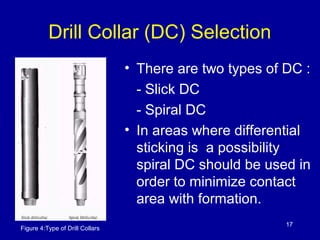
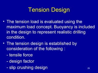
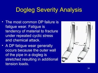
• The greatest tension (P) on drillstring
occurs at top joint at the maximum
drilled depth.
P = [(Ldp xWdp + Ldc xWdc )]x BF
Where :
Ldp = length of DP per foot
Wdp = weight of DP per unit length
Ldc = length of DC per foot
Wdc = weight of DC per unit length
BF = Buoyancy Factor 30](https://image.slidesharecdn.com/9-140910004106-phpapp02/85/Drillstring-BHA-Design-30-320.jpg)

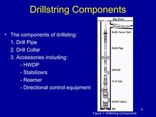
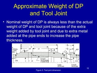
This document discusses the design of drillstrings and bottom hole assemblies (BHAs). It covers the components of drillstrings including drill pipe, drill collars, heavy weight drill pipe, and stabilizers. It also discusses BHA configurations and the purpose and components of BHAs. The document provides information on selecting drill collars and drill pipe grades. It covers criteria for drillstring design including collapse pressure, tension loading, and dogleg severity analysis.


