Downloaded 1,369 times

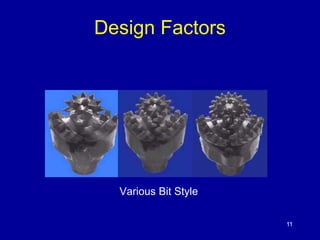
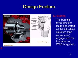
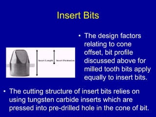
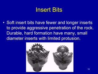
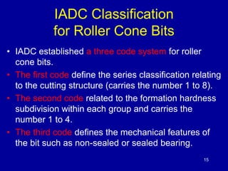
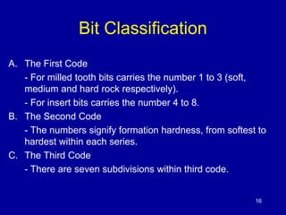
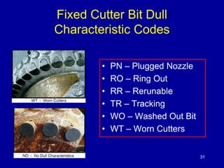
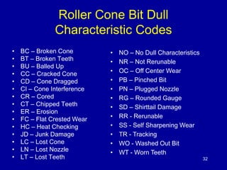
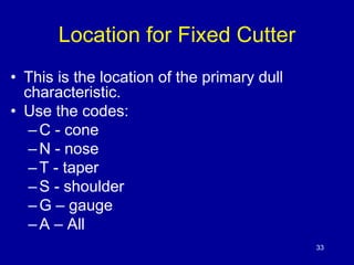
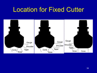
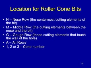
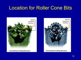


This document discusses different types of drill bits used in drilling operations. It describes roller cone bits, which have three rotating cones with teeth. The design of roller cone bits is influenced by factors like the journal angle, cone offset, tooth shape and angle, and bearing design. The document also discusses insert bits, which use tungsten carbide inserts pressed into the cone, and PDC bits, which employ a layer of polycrystalline diamond. Standards for grading and classifying bits based on wear are also outlined.