Downloaded 3,245 times

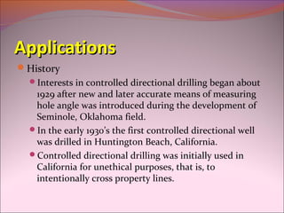


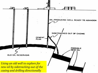
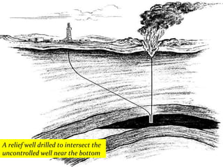
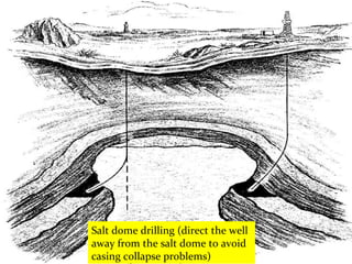
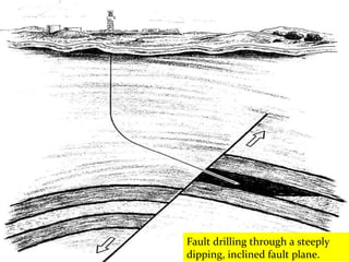

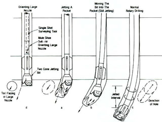


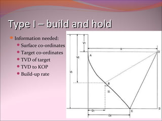


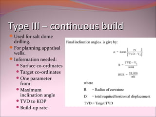


This document provides definitions and information about directional drilling. It discusses the applications of directional drilling including its history and typical uses. It describes the main deflection tools used like whipstocks, jetting bits, and bent subs with mud motors. It also explains the two main types of mud motors - turbines and positive displacement motors. Finally, it outlines the three main types of well profiles: Type I or "build and hold", Type II "build, hold, and drop", and Type III "continuous build".


![[Alghumgham]2011SPEpowerpoint](https://cdn.slidesharecdn.com/ss_thumbnails/8850602d-8d5e-4b61-8bd8-d72c875e4545-151120195603-lva1-app6891-thumbnail.jpg?width=640&height=640&fit=bounds)


