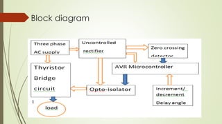
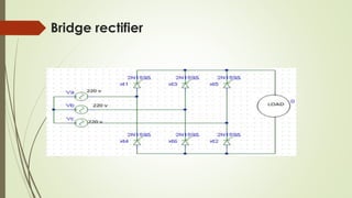
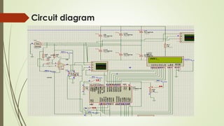
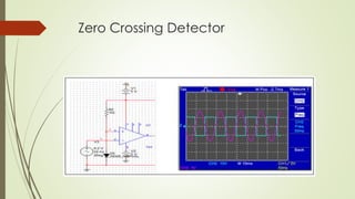
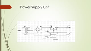
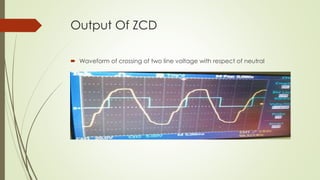
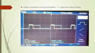
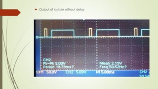
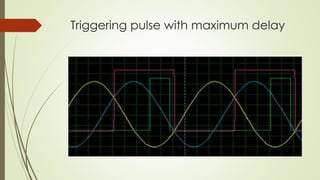
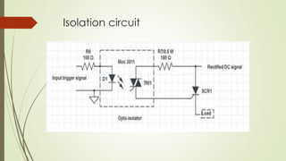
A Presentation On
“Three Phase Fully Controlled Rectifier”
By,
Keshar Rawal (32044)
Suman Shrestha (32048) 10 October 2012
Introduction
Objectives
Applications
Block Diagram
Work Done
Conclusion
OVERVIEW
INTRODUCTION
 Primary energy source are available as AC but many
application needed dc source.
 For high applications, three phase rectifiers are needed
 Variable DC can be obtained using thyristor.
 Microcontroller base thyristor schema is best because
of low loss, low cost and flexibility.
OBJECTIVES
 To design and fabricate three phase fully controlled
rectifier.
 Design microcontroller based control unit.
 To design bridge rectifier circuit. .
APPLICATIONS
 DC motor speed control in industrial application
 Base design for higher power application
 Home appliances
 DC motor drivers
 Battery charger
 Base for the AC-AC converter.
Block diagram
Bridge rectifier
Thyristor conduction schema
 The thyristor are trigged at interval of π/3
 The frequency of output ripple is 6*f
 T1 is triggered at ω*t=(π/6+α), T6 is already conducting when T1 is turned
ON.
 During the interval ( (π/6+α) to (π/2+ α) T1 and T6 conduct together and
output load is equal to Vab=Van-Vbn
 Each thyristor start conduct after 60 degree.
 Out put voltage varies according to that pulse given to gate
Vd= 3𝑉𝑚/𝜋 * cosα cosα =0 for α=90
cosα =1 for α=0
Programe flow chart
Circuit diagram
Zero Crossing Detector
Power Supply Unit
Output Of ZCD
 Waveform of crossing of two line voltage with respect of neutral
 Output waveform of microcontroller’s 1st output pin without delay
 Output of last pin without delay
Triggering pulse with maximum delay
Isolation circuit
fully control rectifier

fully control rectifier