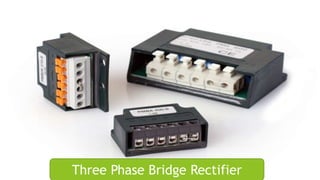
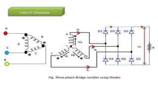
Three Phase Bridge Rectifier
Subject Power Electronics
Presented By
Arsalan Ali
Danish Mansoor
Raja Nouman
Fahad Zafar
FA15-EPE-002
FA15-EPE-012
FA15-EPE-022
FA15-EPE-032
Roll
NO:
Three Phase Bridge Rectifier
CONTENTS
Definition
Three phase supply
Construction
Types of Bridge rectifier
Advantages & Disadvantages
Applications
Characteristics
What is Three Phase Bridge Rectifier ?
Bridge rectifier is a type of rectifier in which diodes
were arranged in the form of a bridge.
In Bridge rectifier six diodes are used to convert the
alternating current(AC) into direct current(DC),
which flows in only one direction.
4 Wires
3 “active” phases, A, B, C
1 “ground”, or “neutral”
Colour Code
Phase A Red
Phase B Blue
Phase C Yellow
Neutral White or Gray
Components for Construction
There are six diodes are used in three phase full bridge
rectifier.
There are two groups:
1)-Top group or Positive group (Diode 1,3 & 5)
2)-Bottom group or Negative group (Diode 2,4 & 6)
Positive group diodes will conduct for positive half cycle.
Negative group diodes will conduct for negative half cycle.
Each diode will conduct for 120 degree in each pair.
TYPES
Full wave RectifierHalf wave Rectifier
When a single rectifier diode unit is placed in series with the load across
an ac supply, it converts alternating voltage into uni-directional pulsating
voltage, using one half cycle of the applied voltage, the other half cycle
being suppressed because it conducts only in one direction. Unless there
is an inductance or battery in the circuit, the current will be zero,
therefore, for half the time. This is called half-wave bridge rectifier.
Half wave Rectifier
During the positive half-cycles of the input ac voltage i.e. when upper
end of the secondary winding is positive w.r.t. its lower end, the diode is
forward biased and therefore conducts current
During the negative half cycles of the input ac voltage i.e. when the
lower end of the secondary winding is positive w.r.t. its upper end, the
diode is reverse biased and so does not conduct
The working of a bridge rectifier is simple. The circuit
diagram of bridge rectifier is given above. The secondary winding
of the transformer is connected to the two diametrically opposite
points of the bridge at points 1,3 and 5. Assume that a load is
connected at the output. The load RLoad is connected to bridge
through points 2,4 and 6.
Working of Full Wave Bridge Rectifier:
This diagram also shows the waveforms for the three-phase sine
waves that supply power to the bridge, and for the six half-waves
of the output pulsing dc voltage. Notice that since the six half-
waves overlap, the dc voltage does not have a chance to get to the
zero voltage point; thus, the average dc output voltage is very high.
In this circuit, the output ripple is six times the input frequency.
Since the ripple percentage is low, the output dc voltage is usable
without much filtering. This type of rectifier is compatible with
transformers that are wye or delta connected.
Characteristics of Bridge Rectifier
Peak Inverse Voltage (PIV):
During the positive half cycle, the diodes D1, D3 and D5are in the
conducting state while the diodes D2 and D4 are in the non-conducting
state. On the other hand, during the negative half cycle, the diodes D2
,D4 and D6are in the conducting state while the diodes D1 and D3 are in
the non-conducting state.
The Peak Inverse Voltage (PIV) for a bridge rectifier is given by
PIV = VSmax
Ripple Factor
The ripple factor for a bridge rectifier is given by
The ripple factor of the bridge rectifier is 0.48 which is same as the
center tapped full wave rectifier.
Rectifier Efficiency
The rectifier efficiency determines how efficiently the
rectifier converts Alternating Current (AC) into Direct
Current (DC).
The maximum rectifier efficiency of a bridge rectifier is
81.2% which is same as the center tapped full wave
rectifier.
Advantages
it does not require a special centre tapped transformer
Ripple frequency is two times the input frequency.
The output and efficiency of full wave bridge rectifier are high
Efficiency is higher The large DC output The ripple factor is less
DISADVANTAGES
PIV rating of diode is higher.
Higher PIV diodes are larger in size and
costlier.
When a small voltage is required to be
rectified this full wave rectifier circuit is
not suitable.
More power loss as compared
to the Center tapped full wave
rectifier
Bridge rectifier circuit looks
very complex
Applications
Because of their low cost compared to center tapped they are widely
used in power supply circuit.
This can be used to detect the amplitude of modulated radio signal.
Bridge rectifiers can be used to supply polarized voltage in welding.
Most industrial power supplies for motor drives which is
widely use in our houses.
THANK YOU

Three Phase Bridge Rectifier

  • 2.
    Three Phase BridgeRectifier Subject Power Electronics
  • 3.
    Presented By Arsalan Ali DanishMansoor Raja Nouman Fahad Zafar FA15-EPE-002 FA15-EPE-012 FA15-EPE-022 FA15-EPE-032 Roll NO:
  • 4.
  • 5.
    CONTENTS Definition Three phase supply Construction Typesof Bridge rectifier Advantages & Disadvantages Applications Characteristics
  • 6.
    What is ThreePhase Bridge Rectifier ? Bridge rectifier is a type of rectifier in which diodes were arranged in the form of a bridge. In Bridge rectifier six diodes are used to convert the alternating current(AC) into direct current(DC), which flows in only one direction.
  • 7.
    4 Wires 3 “active”phases, A, B, C 1 “ground”, or “neutral” Colour Code Phase A Red Phase B Blue Phase C Yellow Neutral White or Gray
  • 8.
    Components for Construction Thereare six diodes are used in three phase full bridge rectifier. There are two groups: 1)-Top group or Positive group (Diode 1,3 & 5) 2)-Bottom group or Negative group (Diode 2,4 & 6) Positive group diodes will conduct for positive half cycle. Negative group diodes will conduct for negative half cycle. Each diode will conduct for 120 degree in each pair.
  • 10.
  • 11.
    When a singlerectifier diode unit is placed in series with the load across an ac supply, it converts alternating voltage into uni-directional pulsating voltage, using one half cycle of the applied voltage, the other half cycle being suppressed because it conducts only in one direction. Unless there is an inductance or battery in the circuit, the current will be zero, therefore, for half the time. This is called half-wave bridge rectifier. Half wave Rectifier During the positive half-cycles of the input ac voltage i.e. when upper end of the secondary winding is positive w.r.t. its lower end, the diode is forward biased and therefore conducts current During the negative half cycles of the input ac voltage i.e. when the lower end of the secondary winding is positive w.r.t. its upper end, the diode is reverse biased and so does not conduct
  • 12.
    The working ofa bridge rectifier is simple. The circuit diagram of bridge rectifier is given above. The secondary winding of the transformer is connected to the two diametrically opposite points of the bridge at points 1,3 and 5. Assume that a load is connected at the output. The load RLoad is connected to bridge through points 2,4 and 6. Working of Full Wave Bridge Rectifier:
  • 13.
    This diagram alsoshows the waveforms for the three-phase sine waves that supply power to the bridge, and for the six half-waves of the output pulsing dc voltage. Notice that since the six half- waves overlap, the dc voltage does not have a chance to get to the zero voltage point; thus, the average dc output voltage is very high. In this circuit, the output ripple is six times the input frequency. Since the ripple percentage is low, the output dc voltage is usable without much filtering. This type of rectifier is compatible with transformers that are wye or delta connected.
  • 14.
    Characteristics of BridgeRectifier Peak Inverse Voltage (PIV): During the positive half cycle, the diodes D1, D3 and D5are in the conducting state while the diodes D2 and D4 are in the non-conducting state. On the other hand, during the negative half cycle, the diodes D2 ,D4 and D6are in the conducting state while the diodes D1 and D3 are in the non-conducting state. The Peak Inverse Voltage (PIV) for a bridge rectifier is given by PIV = VSmax Ripple Factor The ripple factor for a bridge rectifier is given by The ripple factor of the bridge rectifier is 0.48 which is same as the center tapped full wave rectifier.
  • 15.
    Rectifier Efficiency The rectifierefficiency determines how efficiently the rectifier converts Alternating Current (AC) into Direct Current (DC). The maximum rectifier efficiency of a bridge rectifier is 81.2% which is same as the center tapped full wave rectifier.
  • 16.
    Advantages it does notrequire a special centre tapped transformer Ripple frequency is two times the input frequency. The output and efficiency of full wave bridge rectifier are high Efficiency is higher The large DC output The ripple factor is less
  • 17.
    DISADVANTAGES PIV rating ofdiode is higher. Higher PIV diodes are larger in size and costlier. When a small voltage is required to be rectified this full wave rectifier circuit is not suitable. More power loss as compared to the Center tapped full wave rectifier Bridge rectifier circuit looks very complex
  • 18.
    Applications Because of theirlow cost compared to center tapped they are widely used in power supply circuit. This can be used to detect the amplitude of modulated radio signal. Bridge rectifiers can be used to supply polarized voltage in welding. Most industrial power supplies for motor drives which is widely use in our houses.
  • 20.