Downloaded 502 times


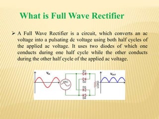

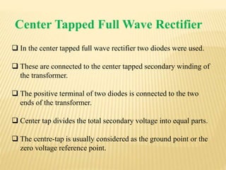
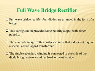
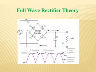
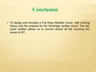


This document discusses full wave rectifier circuits. It defines a full wave rectifier as a circuit that converts AC voltage to pulsating DC voltage using both half cycles of the input voltage. It then describes two types of full wave rectifiers: 1) a center tapped full wave rectifier that uses two diodes connected to the center tapped secondary winding of a transformer, and 2) a full wave bridge rectifier that uses four diodes arranged in a bridge configuration without needing a center tapped transformer. The document concludes by stating that a full wave rectifier allows for almost all incoming AC power to be converted to DC.


