Download as PDF, PPTX
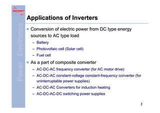
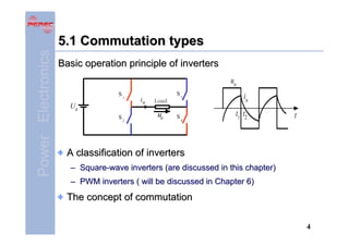
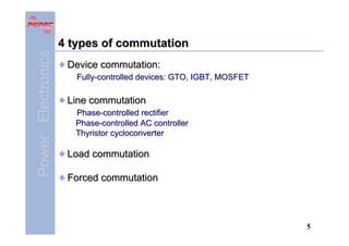
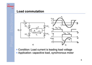
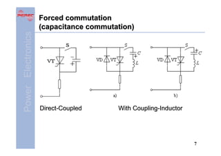
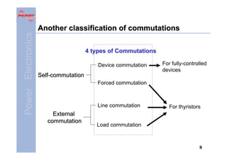
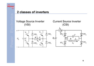

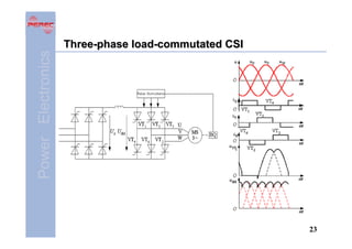
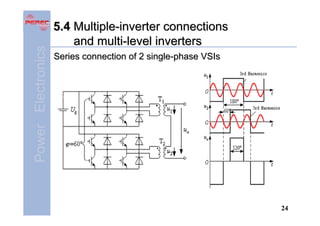
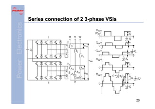
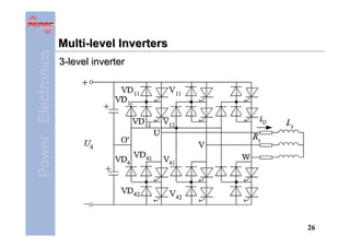

This document provides an overview of DC to AC converters known as inverters. It discusses the different types of commutation used in inverters including device, line, load, and forced commutation. It also summarizes the two main classes of inverters - voltage source inverters and current source inverters. Specific circuit configurations are presented for single and three-phase half bridge, full bridge, and current source inverters. The document concludes with a brief discussion of multiple inverter connections and multi-level inverters.