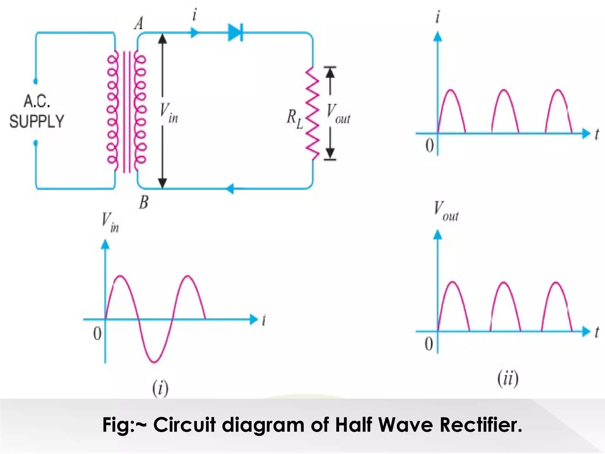
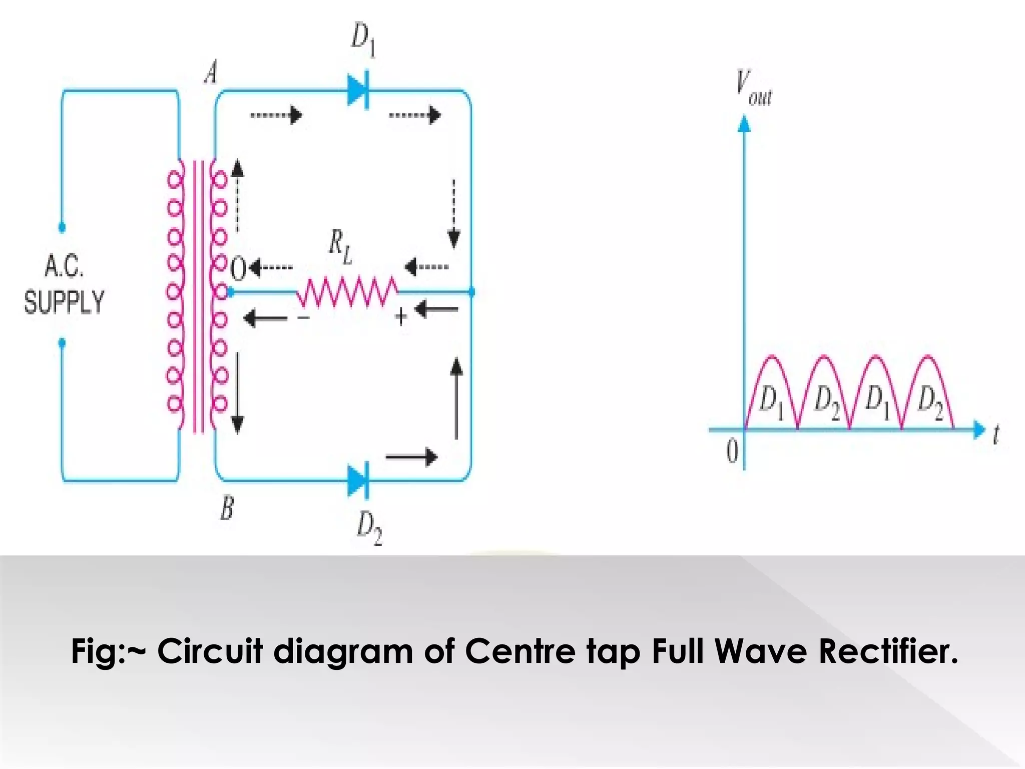
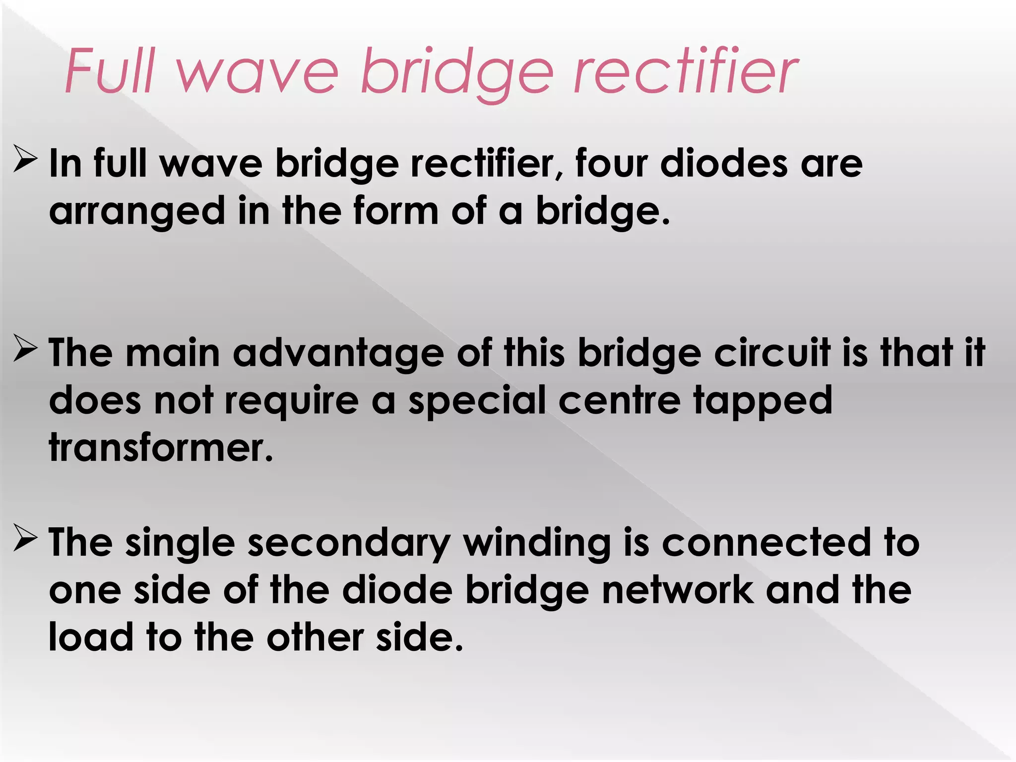
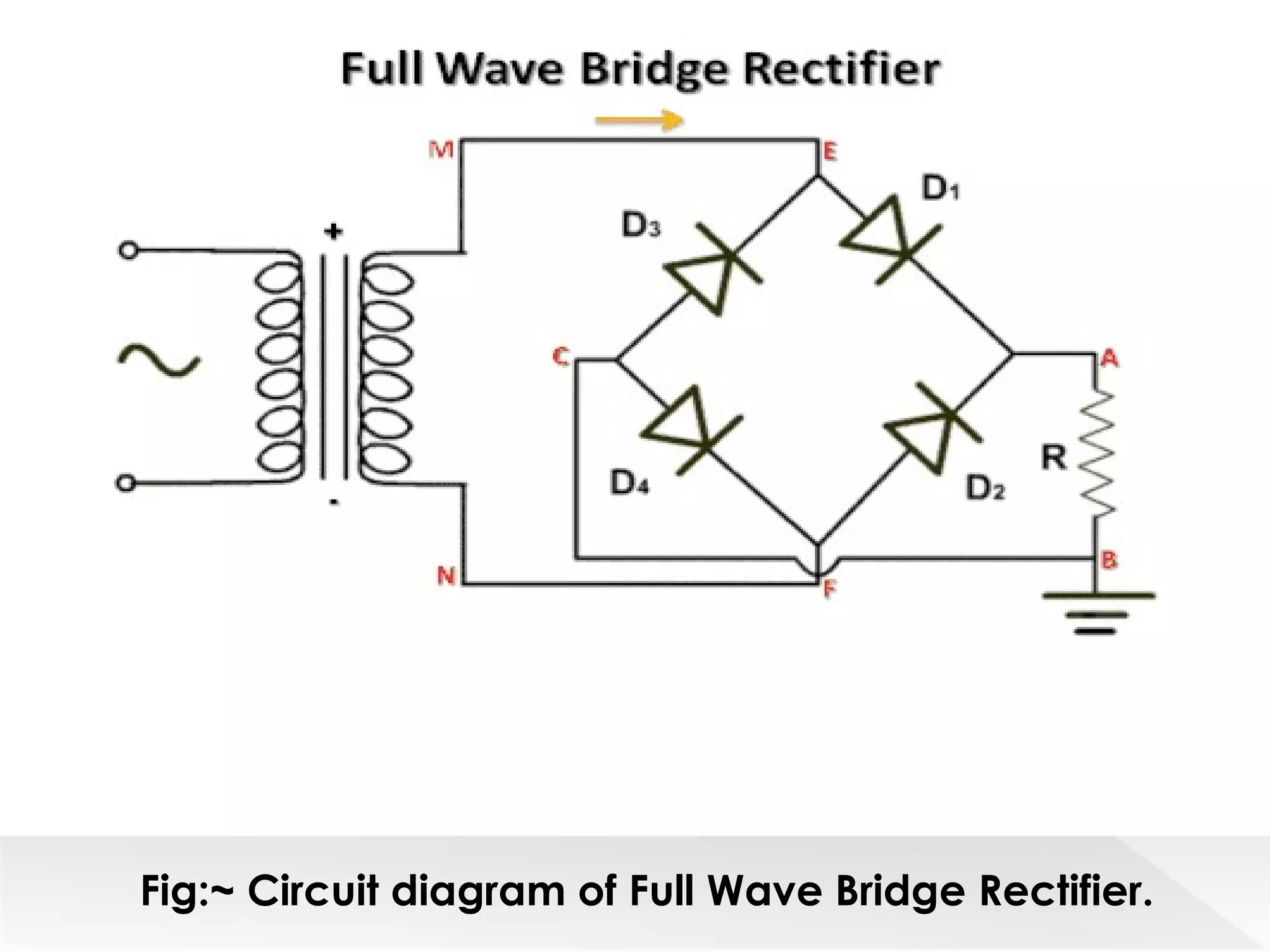
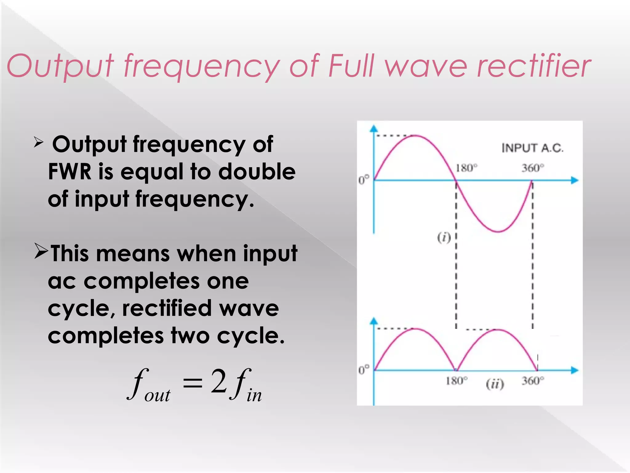
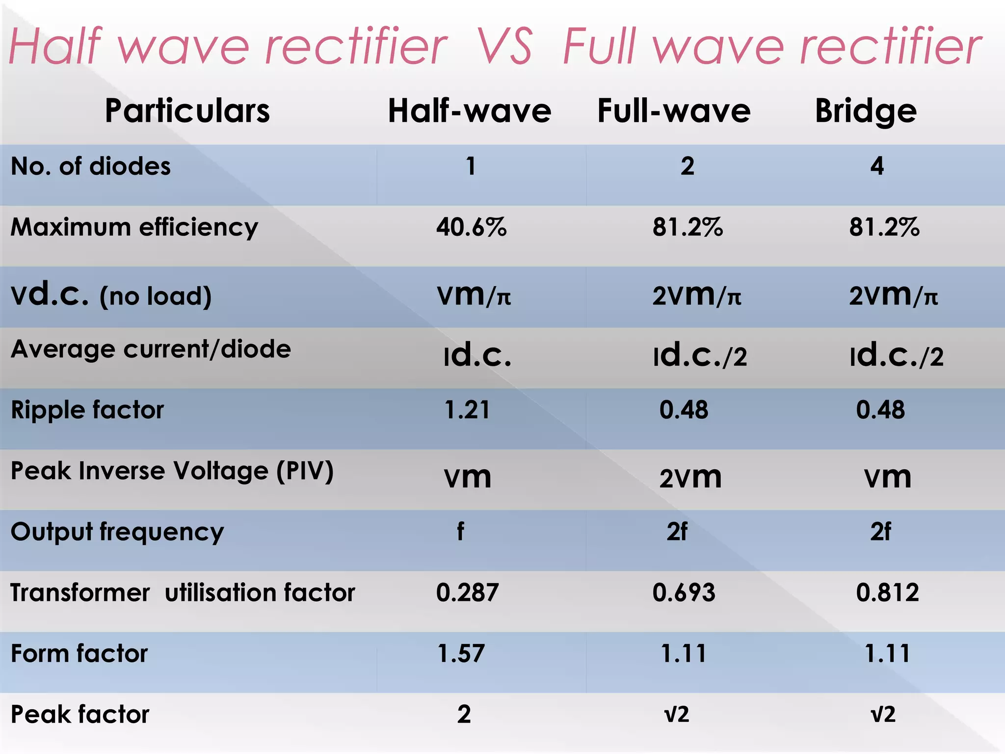
HALF WAVE & FULL WAVE
RECTIFIERS
TRIPURA INSTITUTE OF
TECHNOLOGY
A presentation on:~
Narsingarh, Tripura (West)
Introduction:~
Arectifier is an electrical device that converts the
alternating current (AC) , which periodically reverses
direction, into the direct current (DC) , which flows
only in one direction. This process is known as
Rectification.
Physically, rectifiers take a number of forms,
including vacuum tube diodes, mercury-arc valves,
copper and selenium oxide rectifiers, semiconductor
diodes, silicon-controlled rectifiers and other silicon-
based semiconductor switches.
There are two types of
rectifiers namely:~
1.Half wave rectifier
2.Full wave rectifier
Half Wave Rectifier
 The process of removing one-half of the
input signal to establish a dc level is called
half-wave rectification.
 In Half wave rectification, the rectifier
conducts current during positive half cycle
of input ac signal only.
 Negative half cycle is suppressed.
Fig:~ Circuit diagram of Half Wave Rectifier.
 AC voltage across secondary terminals AB changes
its polarity after each half cycle.
During negative half cycle terminal A is negative so
diode is reversed biased and conducts no current.
So, current flows through diode during positive half
cycle only.
In this way current flows through load RL in one
direction only.
Operation
Output frequency of
HWR is equal to input
frequency.
This means when input
ac completes one
cycle, rectified wave
also completes one
cycle.
Output frequency of Half wave rectifier
inout ff =
Disadvantages:~
The pulsating current in output contains ac
components whose frequency is equal to
supply frequency. So, filtering is needed.
The ac supply delivers power during half cycle
only. So, output is low.
Advantages & Disadvantages
Advantages:~
The circuit of half wave rectifier is very simple
and of low cost.
Full wave Rectifier
 In Full wave rectification current flow
through the load in same direction for
both half cycle of input ac.
 This can be achieved with two diodes
working alternatively.
 For one half cycle one diode supplies
current to load and for next half cycle
another diode works.
Centre tap full wave rectifier
Circuit has two diodes D1 , D2 and a centre tap
transformer.
During positive half cycle, Diode D1 conducts and
during negative half cycle, Diode D2 conducts.
It can be seen that current through load RL is in the
same direction for both the cycles.
Fig:~ Circuit diagram of Centre tap Full Wave Rectifier.
Full wave bridge rectifier
 In full wave bridge rectifier, four diodes are
arranged in the form of a bridge.
 The main advantage of this bridge circuit is that it
does not require a special centre tapped
transformer.
 The single secondary winding is connected to
one side of the diode bridge network and the
load to the other side.
Fig:~ Circuit diagram of Full Wave Bridge Rectifier.
 Output frequency of
FWR is equal to double
of input frequency.
This means when input
ac completes one
cycle, rectified wave
completes two cycle.
inout ff 2=
Output frequency of Full wave rectifier
 Advantages:
I. Need for centre tap transformer is eliminated.
II. Output is twice than that of centre tap circuit.
 Disadvantages:
I. Requires 4 diodes.
II. Internal resistance voltage drop is twice than
that of Centre Tap Circuit.
Advantages & Disadvantages
Half wave rectifier VS Full wave rectifier
Particulars Half-wave Full-wave Bridge
No. of diodes 1 2 4
Maximum efficiency 40.6% 81.2% 81.2%
Vd.c. (no load) Vm/π 2Vm/π 2Vm/π
Average current/diode Id.c. Id.c./2 Id.c./2
Ripple factor 1.21 0.48 0.48
Peak Inverse Voltage (PIV) Vm 2Vm Vm
Output frequency f 2f 2f
Transformer utilisation factor 0.287 0.693 0.812
Form factor 1.57 1.11 1.11
Peak factor 2 √2 √2
THANK YOU All…

Half wave Rectifier & Full wave Rectifier with their descriptions.

  • 1.
    HALF WAVE &FULL WAVE RECTIFIERS TRIPURA INSTITUTE OF TECHNOLOGY A presentation on:~ Narsingarh, Tripura (West)
  • 2.
    Introduction:~ Arectifier is anelectrical device that converts the alternating current (AC) , which periodically reverses direction, into the direct current (DC) , which flows only in one direction. This process is known as Rectification. Physically, rectifiers take a number of forms, including vacuum tube diodes, mercury-arc valves, copper and selenium oxide rectifiers, semiconductor diodes, silicon-controlled rectifiers and other silicon- based semiconductor switches.
  • 3.
    There are twotypes of rectifiers namely:~ 1.Half wave rectifier 2.Full wave rectifier
  • 4.
    Half Wave Rectifier The process of removing one-half of the input signal to establish a dc level is called half-wave rectification.  In Half wave rectification, the rectifier conducts current during positive half cycle of input ac signal only.  Negative half cycle is suppressed.
  • 5.
    Fig:~ Circuit diagramof Half Wave Rectifier.
  • 6.
     AC voltageacross secondary terminals AB changes its polarity after each half cycle. During negative half cycle terminal A is negative so diode is reversed biased and conducts no current. So, current flows through diode during positive half cycle only. In this way current flows through load RL in one direction only. Operation
  • 7.
    Output frequency of HWRis equal to input frequency. This means when input ac completes one cycle, rectified wave also completes one cycle. Output frequency of Half wave rectifier inout ff =
  • 8.
    Disadvantages:~ The pulsating currentin output contains ac components whose frequency is equal to supply frequency. So, filtering is needed. The ac supply delivers power during half cycle only. So, output is low. Advantages & Disadvantages Advantages:~ The circuit of half wave rectifier is very simple and of low cost.
  • 9.
    Full wave Rectifier In Full wave rectification current flow through the load in same direction for both half cycle of input ac.  This can be achieved with two diodes working alternatively.  For one half cycle one diode supplies current to load and for next half cycle another diode works.
  • 10.
    Centre tap fullwave rectifier Circuit has two diodes D1 , D2 and a centre tap transformer. During positive half cycle, Diode D1 conducts and during negative half cycle, Diode D2 conducts. It can be seen that current through load RL is in the same direction for both the cycles.
  • 11.
    Fig:~ Circuit diagramof Centre tap Full Wave Rectifier.
  • 12.
    Full wave bridgerectifier  In full wave bridge rectifier, four diodes are arranged in the form of a bridge.  The main advantage of this bridge circuit is that it does not require a special centre tapped transformer.  The single secondary winding is connected to one side of the diode bridge network and the load to the other side.
  • 13.
    Fig:~ Circuit diagramof Full Wave Bridge Rectifier.
  • 14.
     Output frequencyof FWR is equal to double of input frequency. This means when input ac completes one cycle, rectified wave completes two cycle. inout ff 2= Output frequency of Full wave rectifier
  • 15.
     Advantages: I. Needfor centre tap transformer is eliminated. II. Output is twice than that of centre tap circuit.  Disadvantages: I. Requires 4 diodes. II. Internal resistance voltage drop is twice than that of Centre Tap Circuit. Advantages & Disadvantages
  • 16.
    Half wave rectifierVS Full wave rectifier Particulars Half-wave Full-wave Bridge No. of diodes 1 2 4 Maximum efficiency 40.6% 81.2% 81.2% Vd.c. (no load) Vm/π 2Vm/π 2Vm/π Average current/diode Id.c. Id.c./2 Id.c./2 Ripple factor 1.21 0.48 0.48 Peak Inverse Voltage (PIV) Vm 2Vm Vm Output frequency f 2f 2f Transformer utilisation factor 0.287 0.693 0.812 Form factor 1.57 1.11 1.11 Peak factor 2 √2 √2
  • 17.