Downloaded 1,636 times


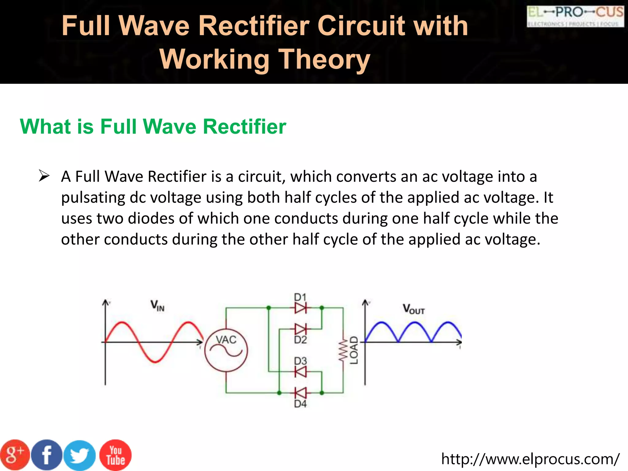
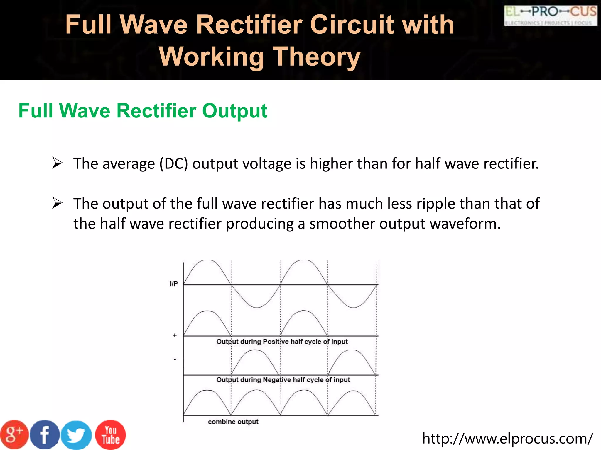


A full wave rectifier converts AC voltage into pulsating DC voltage using two diodes for both half cycles, providing higher average output voltage and reduced ripple compared to half wave rectifiers. It can be classified into center tapped and full wave bridge rectifiers, with the latter utilizing four diodes and not requiring a center tapped transformer, thus reducing cost and size. The full wave rectifier offers advantages like improved efficiency and output but also has drawbacks such as complexity and the need for more diodes.


