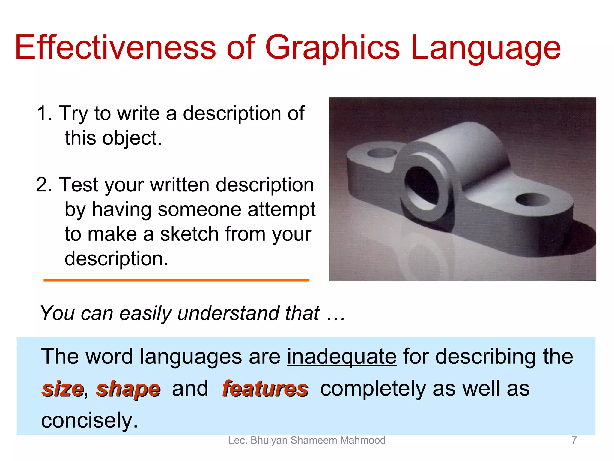
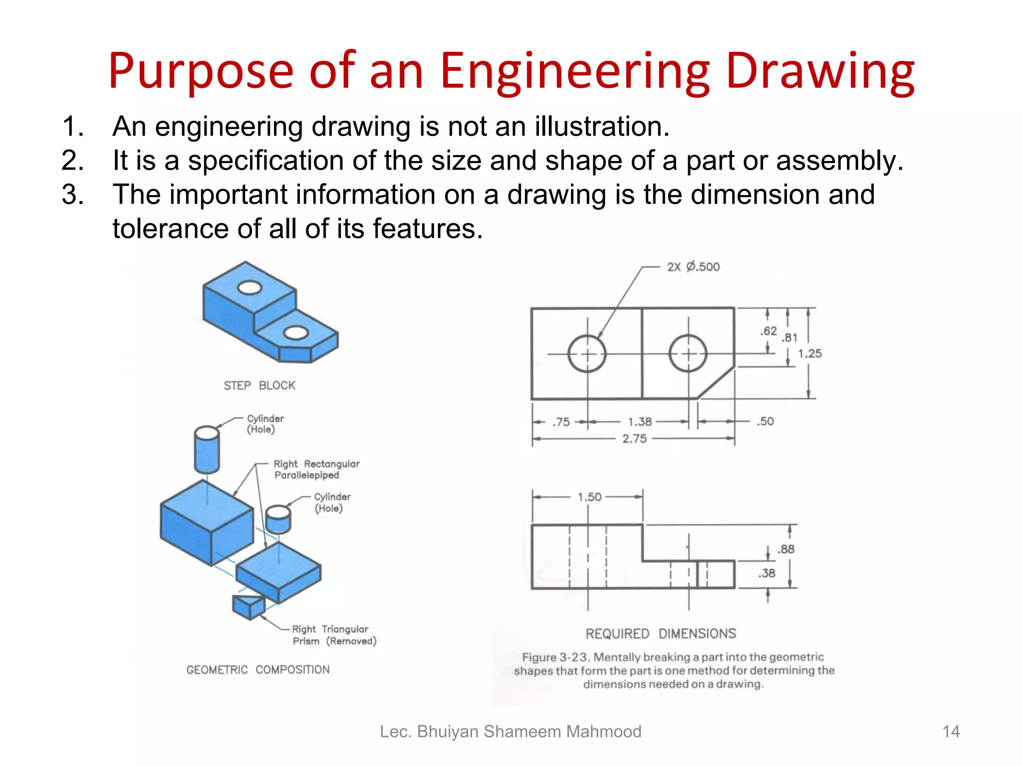
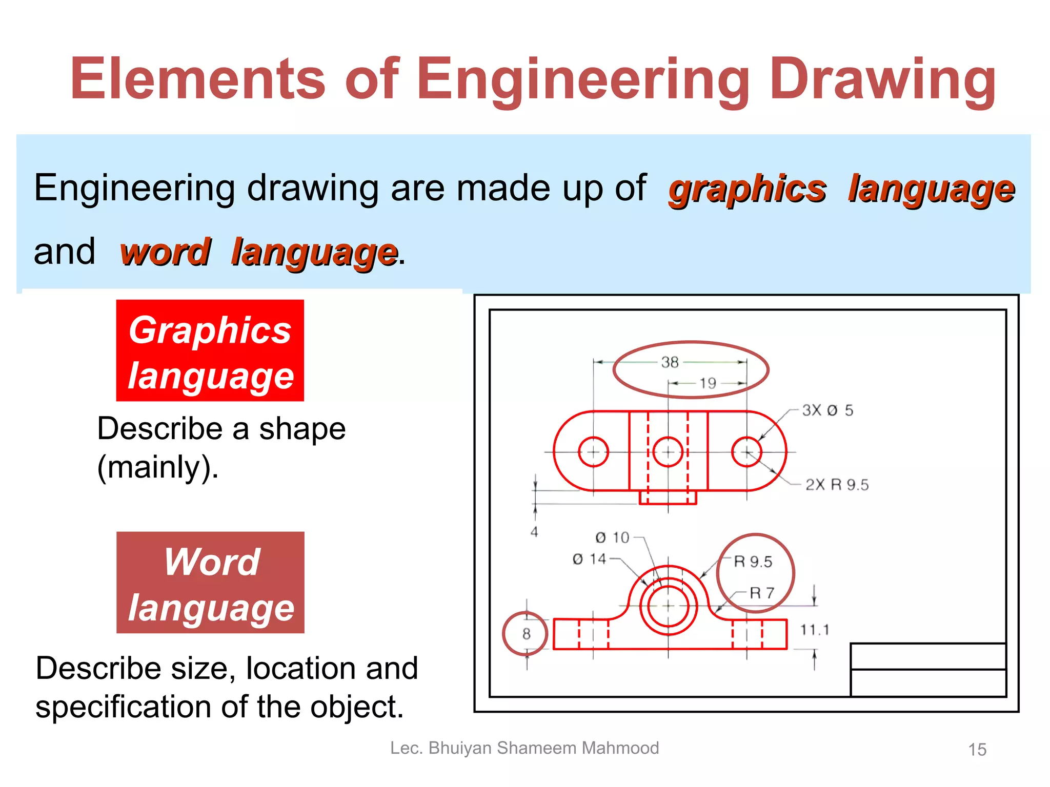
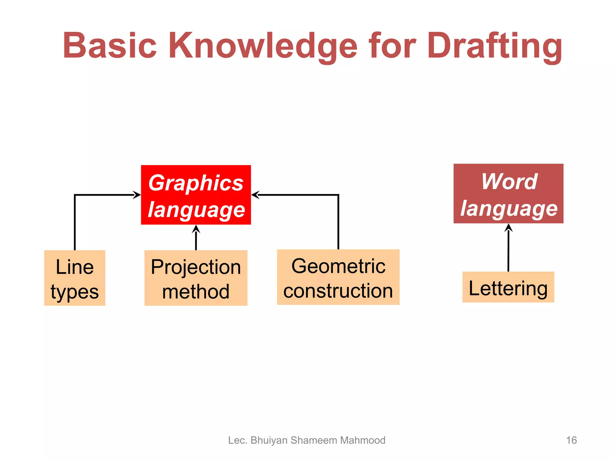
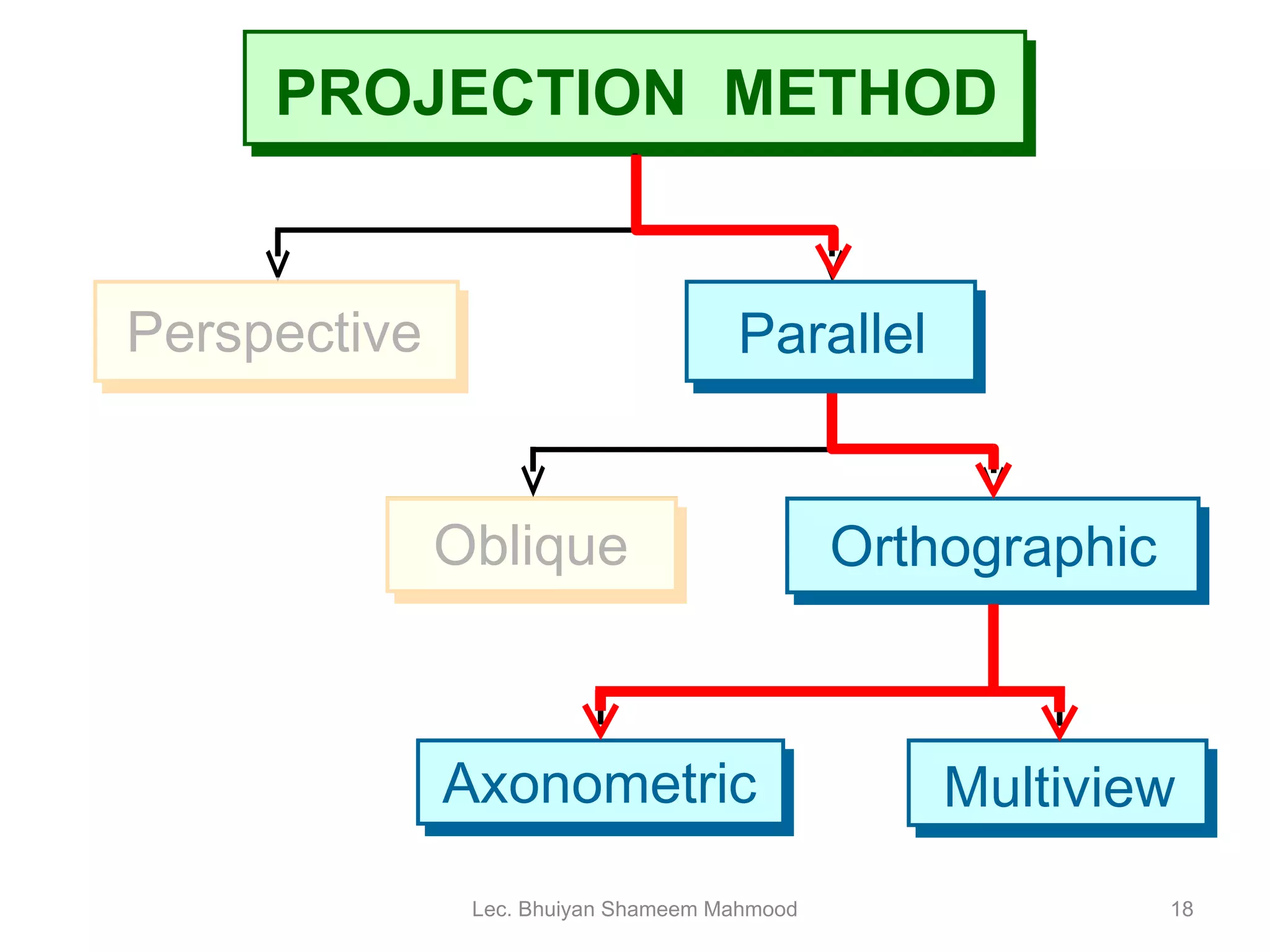
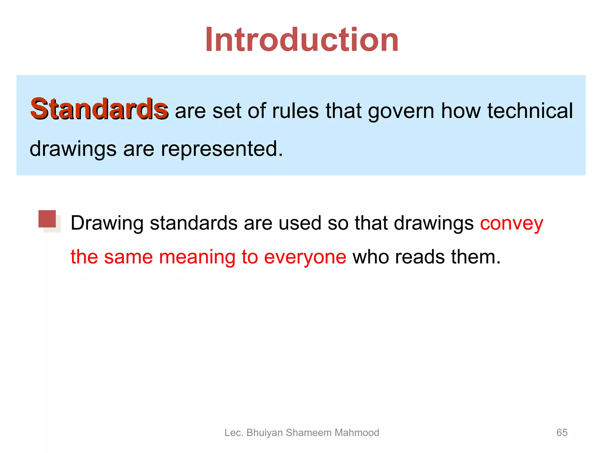
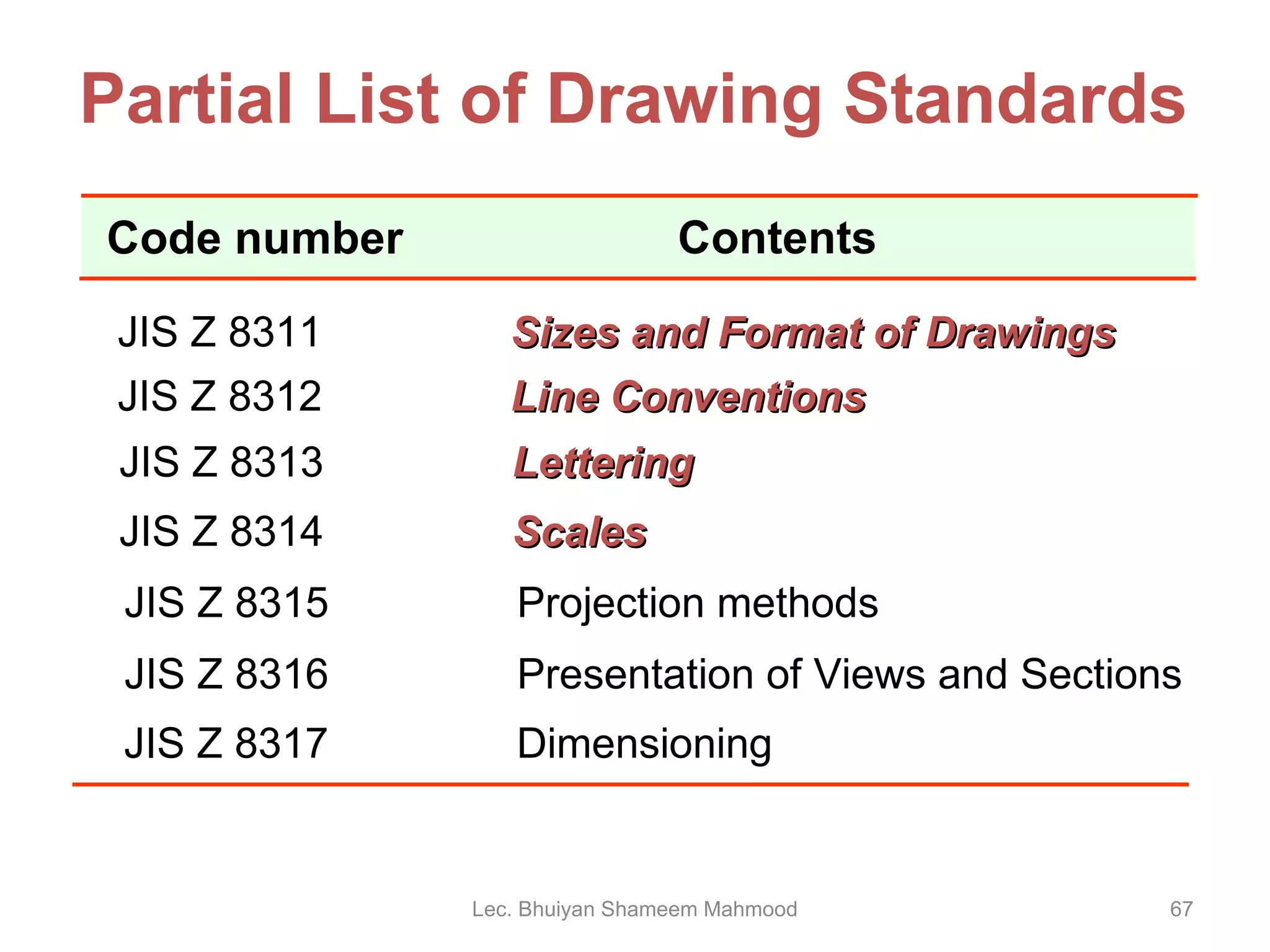
Engineering Drawing –I
Courses outline Introduction; Basic concepts of engineering drawing; Instruments and their uses; First and third angle projections; Orthographic drawings; Principal views, Isometric views; Missing lines and views; Sectional views and conventional practices; Auxiliary views. Lec. Bhuiyan Shameem Mahmood
Text & Ref books Fundamentals of Engineering Drawing  -by French & Vierck. Metric Drafting  –  by Paul Wallah. Drafting Technology and Practice  –  by William P. Spence Mechanical Engineering Drawing -by Dr. Md. Quamrul Islam Lec. Bhuiyan Shameem Mahmood
Class Schedule Introduction: Basic Drawing Practice Orthogonal views of simple block Orthogonal views with circular holes Orthogonal views with fillets and rounds Sectional views Sectional views (conventional practices) Auxiliary views Isometric views Isometric views with circular holes Missing Lines and Missing views. Lec. Bhuiyan Shameem Mahmood
Note: If a student fails to attend in any drawing class, he/she will get  ZERO GRAD  in that drawing. No student will be allowed in the class without necessary  INSTRUMENTS  and  INSTRUCTION SHEET. There will be a  QUIZ EXAM   / an  ORAL EXAM  during the term time. Marks obtained in these exams and those in drawing performed in the classes will be added together to calculate the final grade. Lec. Bhuiyan Shameem Mahmood
Graphics Language Lec. Bhuiyan Shameem Mahmood
1. Try to write a description of this object. 2. Test your written description by having someone attempt   to make a sketch from your description. Effectiveness of Graphics Language The word languages are  inadequate  for describing the  size ,  shape   and  features   completely as well as concisely. You can easily understand that … Lec. Bhuiyan Shameem Mahmood
Graphic language   in   “engineering application”  use l ines   to represent the  surfaces ,  edges   and  contours of objects. Composition of Graphic Language Lec. Bhuiyan Shameem Mahmood A drawing can be done using  freehand ,  instruments   or  computer   methods. The language is known as  “ drawing ”  or  “ drafting ” .
Freehand  drawing   The lines are sketched without using instruments other  than pencils and erasers. Lec. Bhuiyan Shameem Mahmood Example
Instrument drawing   Instruments are used to draw straight lines, circles, and  curves concisely and accurately. Thus, the drawings are usually made to scale. Lec. Bhuiyan Shameem Mahmood Example
Computer  drawing   The drawings are usually made by commercial software such as AutoCAD, solid works etc. Lec. Bhuiyan Shameem Mahmood Example
Engineering Drawing
Introduction An  engineering drawing  is a type of technical drawing, used to fully and clearly define requirements for engineered items, and is usually created in accordance with standardized conventions for layout, nomenclature, interpretation, appearance size, etc. Its purpose is to accurately and unambiguously capture all the geometric features of a product or a component. The end goal of an engineering drawing is to convey all the required information that will allow a manufacturer to produce that component. Lec. Bhuiyan Shameem Mahmood
Purpose of an Engineering Drawing An engineering drawing is not an illustration. It is a specification of the size and shape of a part or assembly. The important information on a drawing is the dimension and tolerance of all of its features. Lec. Bhuiyan Shameem Mahmood
Elements of Engineering Drawing Engineering drawing are made up of  graphics  language and  word  language . Lec. Bhuiyan Shameem Mahmood Graphics language Describe a shape (mainly). Word language Describe size, location and specification of the object.
Basic Knowledge for Drafting Graphics language Word language Lec. Bhuiyan Shameem Mahmood Line types Geometric construction Lettering Projection method
PROJECTION METHOD
PROJECTION  METHOD Lec. Bhuiyan Shameem Mahmood Perspective Oblique Orthographic Axonometric Multiview Parallel
PROJECTION  THEORY Lec. Bhuiyan Shameem Mahmood The projection theory is based on two variables: 1)  Line of sight 2)  Plane of projection  ( image plane or picture plane) The projection theory is used to graphically represent 3-D objects on 2-D media (paper, computer screen).
Line of sight   is an imaginary ray of light between an observer’s eye and an object. Parallel projection Perspective projection parallel converge and Lec. Bhuiyan Shameem Mahmood Line of sight Line of sight There are 2 types of LOS :
Plane of projection   is an imaginary flat plane which  the image is created. Parallel projection Perspective projection Lec. Bhuiyan Shameem Mahmood The image is produced by connecting the points where the LOS pierce the projection plane. Plane of projection Plane of projection
Disadvantage of Perspective  Projection Perspective projection is  not   used by engineer for manu- facturing of parts, because 1) It is difficult to create. 2) It does not reveal exact shape and size. Width is distorted Lec. Bhuiyan Shameem Mahmood
Orthographic  Projection
Orthographic projection Orthographic" comes from the Greek word for "straight writing (or drawing)." This projection shows the object as it looks from the front, right, left, top, bottom, or back, and are typically positioned relative to each other according to the rules of either “First Angle”  or “Third Angle” projection. Lec. Bhuiyan Shameem Mahmood
Pictorial 3-dimensional representations One-point  one vanishing point  lines that are not vertical  or horizontal converge to  single point in distance Two-point or Three-point  two or three vanishing points With two points, vertical  or   horizontal lines parallel, but not both With three-point, no lines are parallel Isometric Drawing shows corner of object,  but parallel lines on object are  parallel in drawing Shows three dimensions, but no  vanishing point(s) Lec. Bhuiyan Shameem Mahmood
One-point Two-Point Lec. Bhuiyan Shameem Mahmood
Symbols for Third Angle (right)or First Angle (left). First angle projection is the ISO standard and is primarily used in Europe. The 3D object is projected into 2D "paper" space as if you were looking at an X-ray of the object: the top view is under the front view, the right view is at the left of the front view.  Third angle projection is primarily used in the United States and Canada, where it is the default projection system according to BS 8888:2006, the left view is placed on the left the top view on the top.  Lec. Bhuiyan Shameem Mahmood
MEANING Orthographic projection   is a parallel projection technique in which the parallel lines of sight are  perpendicular  to the projection plane Lec. Bhuiyan Shameem Mahmood 5 Object views from top Projection plane 1 2 3 4 5 1 2 3 4
Image of a part represented in First Angle Projection Lec. Bhuiyan Shameem Mahmood
Orthographic / Multiview Draw object from two / three perpendicular views / Orthographic What it looks like pictorially Lec. Bhuiyan Shameem Mahmood
Lec. Bhuiyan Shameem Mahmood
ORTHOGRAPHIC  VIEW Orthographic view  depends on relative position of the object to the line of sight. Two dimensions of an object is shown. Three dimensions of an object is shown. Rotate Tilt More than one view is needed to represent the object. Multiview drawing Axonometric drawing Lec. Bhuiyan Shameem Mahmood
Multiview Drawing It represents accurate  shape and size. Advantage Disadvantage Require practice in writing and reading. Multiviews drawing (2-view drawing) Example Lec. Bhuiyan Shameem Mahmood
Axonometric (Isometric) Drawing Easy to understand Right angle becomes obtuse angle. Circular hole becomes ellipse. Distortions of shape and size in isometric drawing Advantage Disadvantage Shape and angle distortion  Example Lec. Bhuiyan Shameem Mahmood
Isometric projection Lec. Bhuiyan Shameem Mahmood
Sectional views Lec. Bhuiyan Shameem Mahmood
Auxiliary Views Used to show true dimensions of an inclined plane. Lec. Bhuiyan Shameem Mahmood
Auxiliary projection Lec. Bhuiyan Shameem Mahmood
Traditional Drawing Tools
Instruments Drawing board/table. Drawing sheet/paper. Drafting tape. Pencils. Eraser. Sharpener. T-square. Set-squares/triangles. Scales. Compass and divider. Lec. Bhuiyan Shameem Mahmood
Drawing board Lec. Bhuiyan Shameem Mahmood
Drawing table Lec. Bhuiyan Shameem Mahmood
Drawing sheet/paper  216 X 280 mm 280 X 382 mm 382 X 560 mm 585 X 726 mm Lec. Bhuiyan Shameem Mahmood
Drafting tape Lec. Bhuiyan Shameem Mahmood
Pencils Wood pencils: H, 2H, 3H, 4H, 5H, 6H, 7H, 8H, 9H, B, HB, 2B, 3B, 4B, 5B, 6B. Semiautomatic Pencils  (lead holder) are more convenient then ordinary wood pencils. Lec. Bhuiyan Shameem Mahmood
Eraser Lec. Bhuiyan Shameem Mahmood
Erasing Shield Lec. Bhuiyan Shameem Mahmood
Sharpener Lec. Bhuiyan Shameem Mahmood
T-square Lec. Bhuiyan Shameem Mahmood
Lec. Bhuiyan Shameem Mahmood
Set-squares/triangles Lec. Bhuiyan Shameem Mahmood
Lec. Bhuiyan Shameem Mahmood
Circle Template Lec. Bhuiyan Shameem Mahmood
Scales Lec. Bhuiyan Shameem Mahmood
Compass and divider Lec. Bhuiyan Shameem Mahmood
Sandpaper Lec. Bhuiyan Shameem Mahmood
Tissue paper Lec. Bhuiyan Shameem Mahmood
Clean paper Lec. Bhuiyan Shameem Mahmood
Drawing  Standard
Introduction Standards  are set of rules that govern how technical drawings are represented. Lec. Bhuiyan Shameem Mahmood Drawing standards are used so that drawings  convey the same meaning to everyone  who reads them.
Standard  Code Lec. Bhuiyan Shameem Mahmood ISO I nternational  S tandards  O rganization ANSI A merican  N ational  S tandard  I nstitute USA JIS J apanese  I ndustrial  S tandard Japan BS B ritish  S tandard UK AS A ustralian  S tandard Australia D eutsches  I nstitut  f ü r   N ormung DIN Germany Country Code Full name มอก . สำนักงานมาตรฐานผลิตภัณฑ์อุตสาหกรรม Thailand
Partial List of Drawing Standards JIS Z 8311    Sizes and Format of Drawings JIS Z 8312    Line Conventions JIS Z 8313    Lettering JIS Z 8314    Scales JIS Z 8315   Projection methods JIS Z 8316   Presentation of Views and Sections JIS Z 8317   Dimensioning Lec. Bhuiyan Shameem Mahmood Code number Contents
Drawing  Sheet Trimmed paper of a size A0 ~ A4. Standard sheet size   ( JIS ) A4   210 x 297 A3   297 x 420 A2   420 x 594 A1   594 x 841 A0   841 x 1189 A4 A3 A2 A1 A0 (Dimensions in millimeters) Lec. Bhuiyan Shameem Mahmood
Drawing space Drawing space Title block Border lines 1. Type X  (A0~A4) 2. Type Y  (A4 only) Title block Lec. Bhuiyan Shameem Mahmood d d c c c Orientation of drawing sheet Sheet size  c (min)  d (min) A4    10  25 A3    10  25  A2    10  25 A1    20  25 A0    20  25
Drawing  Scales Scale   is the ratio of the linear dimension of an element of an object shown in the drawing to the real linear dimension of the same element of the object.  Size in drawing Actual size Length, size Lec. Bhuiyan Shameem Mahmood :
Drawing  Scales SCALE 1:1 for full size SCALE  X :1 for  enlargement   scales  (X > 1) SCALE 1: X for  reduction   scales (X > 1) Lec. Bhuiyan Shameem Mahmood Designation of a scale consists of the word “ SCALE ”  followed by the indication of its  ratio , as follow Dimension numbers shown in the drawing are correspond to “ true size ” of the object  and they are  independent  of the scale used in creating that drawing.
Basic  Line  Types  Types of Lines Appearance Name according to application NOTE  :  We will learn other types of line in later chapters. Lec. Bhuiyan Shameem Mahmood Continuous thick line Visible line Continuous thin line Dimension line Extension line Leader line Dash thick line Hidden line Chain thin line Center line
Visible lines   represent features that can be seen in the current view Meaning of Lines Hidden lines   represent features that  can not be seen  in   the current view Center line   represents symmetry, path of motion, centers   of circles, axis of axisymmetrical parts Dimension and Extension lines   indicate the sizes and    location of features on a drawing Lec. Bhuiyan Shameem Mahmood
Types of Line Lec. Bhuiyan Shameem Mahmood
Line Conventions Visible Lines – solid thick lines that represent visible edges or contours Hidden Lines – short evenly spaced dashes that depict hidden features Section Lines – solid thin lines that indicate cut surfaces Center Lines – alternating long and short dashes Dimensioning Dimension Lines - solid thin lines showing dimension extent/direction Extension Lines - solid thin lines showing point or line to which dimension applies Leaders – direct notes, dimensions, symbols, part numbers, etc. to features on drawing Cutting-Plane and Viewing-Plane Lines – indicate location of cutting planes for sectional views and the viewing position for removed partial views Break Lines – indicate only portion of object is drawn. May be random “squiggled” line or thin dashes joined by zigzags. Phantom Lines – long thin dashes separated by pairs of short dashes indicate alternate positions of moving parts, adjacent position of related parts and repeated detail Chain Line – Lines or surfaces with special requirements Lec. Bhuiyan Shameem Mahmood
1 2 3 4 5 6 7 8 9 10 14 13 12 11 Viewing-plane line Extension line Dimension Line Center Line Hidden Line Break Line Cutting-plane Line Visible Line Center Line (of motion) Leader VIEW B-B SECTION A-A Section Line Phantom Line Lec. Bhuiyan Shameem Mahmood
ABCDEFGHIJKLMNOPQRSTUVWXYZABCDEFGHIJKLMNOPQRSTUVWXYZABCD ABCDEFGHIJKLMNOPQRSTUVWXYZABCDEFGHIJKLMNOPQRSTUVWXYZABCDEF Lettering
Text on Drawings Text on engineering drawing is used : Thus, it must be written with Lec. Bhuiyan Shameem Mahmood To communicate nongraphic information. As a substitute for graphic information, in those instance where text can communicate the needed information more clearly and quickly. Uniformity - size - line thickness Legibility - shape - space between letters and words
Example Placement of the text on drawing Lec. Bhuiyan Shameem Mahmood Dimension & Notes Notes Title Block
Lettering Standard ANSI  Standard This course Lec. Bhuiyan Shameem Mahmood Use a Gothic text style, either inclined or vertical. Use all capital letters. Use 3 mm for most text height. Space between lines of text is  at least  1/3 of text height. Use only a vertical Gothic text style. Use both capital and lower-case letters. Same. For letters in title block it is recommend to use 5~8 mm text height N/A. Follows ANSI rule.
Basic Strokes Straight Slanted Curved Horizontal 1 1 2 3 Examples :  Application of basic stroke “ I ” letter “ A ” letter 1 2 3 4 5 6 “ B ” letter Lec. Bhuiyan Shameem Mahmood
Suggested Strokes Sequence Straight line letters Curved line letters Curved line letters & Numerals Upper-case letters & Numerals Lec. Bhuiyan Shameem Mahmood
The text’ s body height is about  2/3  the height of a capital letter. Suggested Strokes Sequence Lower-case letters Lec. Bhuiyan Shameem Mahmood
Stroke Sequence I L T F E H Lec. Bhuiyan Shameem Mahmood
Stroke Sequence V X W Lec. Bhuiyan Shameem Mahmood
Stroke Sequence N M K Z Y A 4 Lec. Bhuiyan Shameem Mahmood
Stroke Sequence O Q C G Lec. Bhuiyan Shameem Mahmood
Stroke Sequence D U P B R J 1 2 Lec. Bhuiyan Shameem Mahmood
Stroke Sequence 5 7 Lec. Bhuiyan Shameem Mahmood
Stroke Sequence 6 8 9 0 S 3 Lec. Bhuiyan Shameem Mahmood
Stroke Sequence l i Lec. Bhuiyan Shameem Mahmood
Stroke Sequence v w x k z Lec. Bhuiyan Shameem Mahmood
Stroke Sequence j y f r t Lec. Bhuiyan Shameem Mahmood
Stroke Sequence c o a b d p q e Lec. Bhuiyan Shameem Mahmood
Stroke Sequence g n m h u s Lec. Bhuiyan Shameem Mahmood
Word  Composition Look at the same word having different spacing between letters. JIRAPONG Which one is easier to read ? A) Non-uniform spacing B) Uniform spacing J I G O R N P A
Word  Composition JIRAPONG \   / )( Spacing Contour General conclusions are: Lec. Bhuiyan Shameem Mahmood \ | ) | ( | Space between the letters depends on the contour of the letters at an adjacent side. | | | | Good spacing creates approximately equal  background area  between letters.
GOOD Not uniform in style. Not uniform in height. Not uniformly vertical or inclined. Not uniform in thickness of stroke. Area between letters not uniform. Area between words not uniform. Example  :  Good and Poor Lettering Lec. Bhuiyan Shameem Mahmood
Leave the space between words equal to the space requires for writing a letter “O”.  Example Sentence  Composition ALL DIMENSIONS ARE IN MILLIMETERS O O O O UNLESS OTHERWISE SPECIFIED. O Lec. Bhuiyan Shameem Mahmood
Dimensioning
Dimensioning Guidelines The term “feature” refers to surfaces, faces, holes, slots, corners, bends, arcs and fillets that add  up to form an engineering part. Dimensions define the  size  of a feature or its  location  relative to other features or a frame of reference, called a datum. The basic rules of dimensioning are: Dimension where the feature contour is shown; Place dimensions between the views; Dimension off the views; Dimension mating features for assembly; Do not dimension to hidden lines; Stagger dimensioning values; Create a logical arrangement of dimensions; Consider fabrication processes and capabilities; Consider inspection processes and capabilities. Lec. Bhuiyan Shameem Mahmood
Important elements of dimensioning Two types of dimensioning: (1) Size and location dimensions and (2) Detail dimensioning Lec. Bhuiyan Shameem Mahmood
Geometrics  The science of specifying and tolerancing shapes and locations of features of on objects Lec. Bhuiyan Shameem Mahmood
Geometrics  It is important that all persons reading a drawing interpret it exactly the same way. Parts are dimensioned based on two criteria: Basic size and locations of the features Details of construction for manufacturing Standards from ANSI (American National Standards Institute) Lec. Bhuiyan Shameem Mahmood
Scaling vs. Dimensioning Drawings can be a different scales, but dimensions are ALWAYS at full scale. Lec. Bhuiyan Shameem Mahmood
Units of Measure Length English - Inches, unless otherwise stated Up to 72 inches – feet and inches over SI – millimeter, mm Angle degrees, minutes, seconds Angle Dimensions Lec. Bhuiyan Shameem Mahmood
Elements of a dimensioned drawing (Be familiar with these terms Lec. Bhuiyan Shameem Mahmood
Arrangement of Dimensions Keep dimension off of the part where possible. Arrange extension lines so the larger dimensions are outside of the smaller dimensions. Stagger the dimension value labels to ensure they are clearly defined.
Dimensioning Holes Dimension the diameter of a hole. Locate the center-line. Use a notes and designators for repeated hole sizes
Dimensioning the Radius of an Arc Dimension an arcs by its radius. Locate the center of the radius or two tangents to the arc.
Drilled Holes, Counter bores and Countersinks Use the depth symbol to define the depth of a drilled hole. Use the depth symbol or a section view to dimension a counter bore. Countersinks do not need a section view.
Angles, Chamfers and Tapers Dimension the one vertex for an angled face, the other vertex is determined by an intersection. Chamfers are generally 45    with the width of the face specified.
Rounded Bars and Slots The rounded end of a bar or slot has a radius that is 1/2 its width. Use R to denote this radius, do not dimension it twice. Locate the center of the arc, or the center of the slot.
Limits of Size All dimensions have minimum and maximum values specified by the tolerance block. Tolerances accumulate in a chain of dimensions. Accumulation can be avoided by using a single baseline.
Fit Between Parts Clearance Fit Interference Fit Transition Fit Clearance fit:  The shaft maximum diameter is smaller than the hole minimum diameter. Interference fit:  The shaft minimum diameter is larger than the hole maximum diameter. Transition fit:  The shaft maximum diameter and hole minimum have an interference fit, while the shaft minimum diameter and hole maximum diameter have a clearance fit
Dimensioning standards P.
Dimension text placement P.
Unidirectional or aligned dimensioning? Lec. Bhuiyan Shameem Mahmood
Dual dimensioning
Dimensioning Basic Shapes -Assumptions Perpendicularity Assume lines that appear perpendicular to be 90° unless otherwise noted Symmetry If a part appears symmetrical – it is (unless it is dimensioned otherwise) Holes in the center of a cylindrical object are automatically located
Dimensioning Basic Shapes Rectangular Prism
Dimensioning Basic Shapes Cylinders Positive Negative
Dimensioning Basic Shapes Cone    Frustum
Dimensioning Basic Shapes Circle Pattern Center Lines Lec. Bhuiyan Shameem Mahmood
Grouping Dimensions Dimensions should always be placed outside the part Lec. Bhuiyan Shameem Mahmood Yes No
Dimension guidelines Dimensions should be placed in the view that most clearly describes the feature being dimensioned (contour (shape) dimensioning) Lec. Bhuiyan Shameem Mahmood
Dimension guidelines Maintain a minimum spacing between the object and the dimension between multiple dimensions. A visible gap shall be placed between the ends of extension lines and the feature to which they refer. Lec. Bhuiyan Shameem Mahmood
Dimension guidelines Avoid dimensioning hidden lines. Leader lines for diameters and radii should be radial lines. Lec. Bhuiyan Shameem Mahmood
Where and how should we place dimensions when we have many dimensions? Lec. Bhuiyan Shameem Mahmood
Where and how should we place dimensions when we have many dimensions? (cont.) Lec. Bhuiyan Shameem Mahmood
Staggering Dimensions Put the lesser dimensions closer to the part. Try to reference dimensions from one surface This will depend on the part and how the tolerances are based. Lec. Bhuiyan Shameem Mahmood
Extension Line Practices Lec. Bhuiyan Shameem Mahmood
Repetitive Features Use the Symbol ‘x’ to Dimension Repetitive Features Lec. Bhuiyan Shameem Mahmood
Symbols for Drilling Operations Lec. Bhuiyan Shameem Mahmood
References  Lec. Bhuiyan Shameem Mahmood T. Dragomatz “ Introduction to Engineering”, by Paul Wright “ Design Dimensioning and Tolerance”, by J. M. McCarthy Dr. Ashish K Darpe

Engineering Drawing

  • 1.
  • 2.
    Courses outline Introduction;Basic concepts of engineering drawing; Instruments and their uses; First and third angle projections; Orthographic drawings; Principal views, Isometric views; Missing lines and views; Sectional views and conventional practices; Auxiliary views. Lec. Bhuiyan Shameem Mahmood
  • 3.
    Text & Refbooks Fundamentals of Engineering Drawing -by French & Vierck. Metric Drafting – by Paul Wallah. Drafting Technology and Practice – by William P. Spence Mechanical Engineering Drawing -by Dr. Md. Quamrul Islam Lec. Bhuiyan Shameem Mahmood
  • 4.
    Class Schedule Introduction:Basic Drawing Practice Orthogonal views of simple block Orthogonal views with circular holes Orthogonal views with fillets and rounds Sectional views Sectional views (conventional practices) Auxiliary views Isometric views Isometric views with circular holes Missing Lines and Missing views. Lec. Bhuiyan Shameem Mahmood
  • 5.
    Note: If astudent fails to attend in any drawing class, he/she will get ZERO GRAD in that drawing. No student will be allowed in the class without necessary INSTRUMENTS and INSTRUCTION SHEET. There will be a QUIZ EXAM / an ORAL EXAM during the term time. Marks obtained in these exams and those in drawing performed in the classes will be added together to calculate the final grade. Lec. Bhuiyan Shameem Mahmood
  • 6.
    Graphics Language Lec.Bhuiyan Shameem Mahmood
  • 7.
    1. Try towrite a description of this object. 2. Test your written description by having someone attempt to make a sketch from your description. Effectiveness of Graphics Language The word languages are inadequate for describing the size , shape and features completely as well as concisely. You can easily understand that … Lec. Bhuiyan Shameem Mahmood
  • 8.
    Graphic language in “engineering application” use l ines to represent the surfaces , edges and contours of objects. Composition of Graphic Language Lec. Bhuiyan Shameem Mahmood A drawing can be done using freehand , instruments or computer methods. The language is known as “ drawing ” or “ drafting ” .
  • 9.
    Freehand drawing The lines are sketched without using instruments other than pencils and erasers. Lec. Bhuiyan Shameem Mahmood Example
  • 10.
    Instrument drawing Instruments are used to draw straight lines, circles, and curves concisely and accurately. Thus, the drawings are usually made to scale. Lec. Bhuiyan Shameem Mahmood Example
  • 11.
    Computer drawing The drawings are usually made by commercial software such as AutoCAD, solid works etc. Lec. Bhuiyan Shameem Mahmood Example
  • 12.
  • 13.
    Introduction An engineering drawing is a type of technical drawing, used to fully and clearly define requirements for engineered items, and is usually created in accordance with standardized conventions for layout, nomenclature, interpretation, appearance size, etc. Its purpose is to accurately and unambiguously capture all the geometric features of a product or a component. The end goal of an engineering drawing is to convey all the required information that will allow a manufacturer to produce that component. Lec. Bhuiyan Shameem Mahmood
  • 14.
    Purpose of anEngineering Drawing An engineering drawing is not an illustration. It is a specification of the size and shape of a part or assembly. The important information on a drawing is the dimension and tolerance of all of its features. Lec. Bhuiyan Shameem Mahmood
  • 15.
    Elements of EngineeringDrawing Engineering drawing are made up of graphics language and word language . Lec. Bhuiyan Shameem Mahmood Graphics language Describe a shape (mainly). Word language Describe size, location and specification of the object.
  • 16.
    Basic Knowledge forDrafting Graphics language Word language Lec. Bhuiyan Shameem Mahmood Line types Geometric construction Lettering Projection method
  • 17.
  • 18.
    PROJECTION METHODLec. Bhuiyan Shameem Mahmood Perspective Oblique Orthographic Axonometric Multiview Parallel
  • 19.
    PROJECTION THEORYLec. Bhuiyan Shameem Mahmood The projection theory is based on two variables: 1) Line of sight 2) Plane of projection ( image plane or picture plane) The projection theory is used to graphically represent 3-D objects on 2-D media (paper, computer screen).
  • 20.
    Line of sight is an imaginary ray of light between an observer’s eye and an object. Parallel projection Perspective projection parallel converge and Lec. Bhuiyan Shameem Mahmood Line of sight Line of sight There are 2 types of LOS :
  • 21.
    Plane of projection is an imaginary flat plane which the image is created. Parallel projection Perspective projection Lec. Bhuiyan Shameem Mahmood The image is produced by connecting the points where the LOS pierce the projection plane. Plane of projection Plane of projection
  • 22.
    Disadvantage of Perspective Projection Perspective projection is not used by engineer for manu- facturing of parts, because 1) It is difficult to create. 2) It does not reveal exact shape and size. Width is distorted Lec. Bhuiyan Shameem Mahmood
  • 23.
  • 24.
    Orthographic projection Orthographic"comes from the Greek word for "straight writing (or drawing)." This projection shows the object as it looks from the front, right, left, top, bottom, or back, and are typically positioned relative to each other according to the rules of either “First Angle” or “Third Angle” projection. Lec. Bhuiyan Shameem Mahmood
  • 25.
    Pictorial 3-dimensional representationsOne-point one vanishing point lines that are not vertical or horizontal converge to single point in distance Two-point or Three-point two or three vanishing points With two points, vertical or horizontal lines parallel, but not both With three-point, no lines are parallel Isometric Drawing shows corner of object, but parallel lines on object are parallel in drawing Shows three dimensions, but no vanishing point(s) Lec. Bhuiyan Shameem Mahmood
  • 26.
    One-point Two-Point Lec.Bhuiyan Shameem Mahmood
  • 27.
    Symbols for ThirdAngle (right)or First Angle (left). First angle projection is the ISO standard and is primarily used in Europe. The 3D object is projected into 2D "paper" space as if you were looking at an X-ray of the object: the top view is under the front view, the right view is at the left of the front view. Third angle projection is primarily used in the United States and Canada, where it is the default projection system according to BS 8888:2006, the left view is placed on the left the top view on the top. Lec. Bhuiyan Shameem Mahmood
  • 28.
    MEANING Orthographic projection is a parallel projection technique in which the parallel lines of sight are perpendicular to the projection plane Lec. Bhuiyan Shameem Mahmood 5 Object views from top Projection plane 1 2 3 4 5 1 2 3 4
  • 29.
    Image of apart represented in First Angle Projection Lec. Bhuiyan Shameem Mahmood
  • 30.
    Orthographic / MultiviewDraw object from two / three perpendicular views / Orthographic What it looks like pictorially Lec. Bhuiyan Shameem Mahmood
  • 31.
  • 32.
  • 33.
    ORTHOGRAPHIC VIEWOrthographic view depends on relative position of the object to the line of sight. Two dimensions of an object is shown. Three dimensions of an object is shown. Rotate Tilt More than one view is needed to represent the object. Multiview drawing Axonometric drawing Lec. Bhuiyan Shameem Mahmood
  • 34.
    Multiview Drawing Itrepresents accurate shape and size. Advantage Disadvantage Require practice in writing and reading. Multiviews drawing (2-view drawing) Example Lec. Bhuiyan Shameem Mahmood
  • 35.
    Axonometric (Isometric) DrawingEasy to understand Right angle becomes obtuse angle. Circular hole becomes ellipse. Distortions of shape and size in isometric drawing Advantage Disadvantage Shape and angle distortion Example Lec. Bhuiyan Shameem Mahmood
  • 36.
    Isometric projection Lec.Bhuiyan Shameem Mahmood
  • 37.
    Isometric projection Lec.Bhuiyan Shameem Mahmood
  • 38.
    Sectional views Lec.Bhuiyan Shameem Mahmood
  • 39.
    Auxiliary Views Usedto show true dimensions of an inclined plane. Lec. Bhuiyan Shameem Mahmood
  • 40.
    Auxiliary projection Lec.Bhuiyan Shameem Mahmood
  • 41.
    Auxiliary projection Lec.Bhuiyan Shameem Mahmood
  • 42.
  • 43.
    Instruments Drawing board/table.Drawing sheet/paper. Drafting tape. Pencils. Eraser. Sharpener. T-square. Set-squares/triangles. Scales. Compass and divider. Lec. Bhuiyan Shameem Mahmood
  • 44.
    Drawing board Lec.Bhuiyan Shameem Mahmood
  • 45.
    Drawing table Lec.Bhuiyan Shameem Mahmood
  • 46.
    Drawing sheet/paper 216 X 280 mm 280 X 382 mm 382 X 560 mm 585 X 726 mm Lec. Bhuiyan Shameem Mahmood
  • 47.
    Drafting tape Lec.Bhuiyan Shameem Mahmood
  • 48.
    Pencils Wood pencils:H, 2H, 3H, 4H, 5H, 6H, 7H, 8H, 9H, B, HB, 2B, 3B, 4B, 5B, 6B. Semiautomatic Pencils (lead holder) are more convenient then ordinary wood pencils. Lec. Bhuiyan Shameem Mahmood
  • 49.
    Eraser Lec. BhuiyanShameem Mahmood
  • 50.
    Erasing Shield Lec.Bhuiyan Shameem Mahmood
  • 51.
    Sharpener Lec. BhuiyanShameem Mahmood
  • 52.
    T-square Lec. BhuiyanShameem Mahmood
  • 53.
  • 54.
  • 55.
  • 56.
  • 57.
  • 58.
    Circle Template Lec.Bhuiyan Shameem Mahmood
  • 59.
    Scales Lec. BhuiyanShameem Mahmood
  • 60.
    Compass and dividerLec. Bhuiyan Shameem Mahmood
  • 61.
    Sandpaper Lec. BhuiyanShameem Mahmood
  • 62.
    Tissue paper Lec.Bhuiyan Shameem Mahmood
  • 63.
    Clean paper Lec.Bhuiyan Shameem Mahmood
  • 64.
  • 65.
    Introduction Standards are set of rules that govern how technical drawings are represented. Lec. Bhuiyan Shameem Mahmood Drawing standards are used so that drawings convey the same meaning to everyone who reads them.
  • 66.
    Standard CodeLec. Bhuiyan Shameem Mahmood ISO I nternational S tandards O rganization ANSI A merican N ational S tandard I nstitute USA JIS J apanese I ndustrial S tandard Japan BS B ritish S tandard UK AS A ustralian S tandard Australia D eutsches I nstitut f ü r N ormung DIN Germany Country Code Full name มอก . สำนักงานมาตรฐานผลิตภัณฑ์อุตสาหกรรม Thailand
  • 67.
    Partial List ofDrawing Standards JIS Z 8311 Sizes and Format of Drawings JIS Z 8312 Line Conventions JIS Z 8313 Lettering JIS Z 8314 Scales JIS Z 8315 Projection methods JIS Z 8316 Presentation of Views and Sections JIS Z 8317 Dimensioning Lec. Bhuiyan Shameem Mahmood Code number Contents
  • 68.
    Drawing SheetTrimmed paper of a size A0 ~ A4. Standard sheet size ( JIS ) A4 210 x 297 A3 297 x 420 A2 420 x 594 A1 594 x 841 A0 841 x 1189 A4 A3 A2 A1 A0 (Dimensions in millimeters) Lec. Bhuiyan Shameem Mahmood
  • 69.
    Drawing space Drawingspace Title block Border lines 1. Type X (A0~A4) 2. Type Y (A4 only) Title block Lec. Bhuiyan Shameem Mahmood d d c c c Orientation of drawing sheet Sheet size c (min) d (min) A4 10 25 A3 10 25 A2 10 25 A1 20 25 A0 20 25
  • 70.
    Drawing ScalesScale is the ratio of the linear dimension of an element of an object shown in the drawing to the real linear dimension of the same element of the object. Size in drawing Actual size Length, size Lec. Bhuiyan Shameem Mahmood :
  • 71.
    Drawing ScalesSCALE 1:1 for full size SCALE X :1 for enlargement scales (X > 1) SCALE 1: X for reduction scales (X > 1) Lec. Bhuiyan Shameem Mahmood Designation of a scale consists of the word “ SCALE ” followed by the indication of its ratio , as follow Dimension numbers shown in the drawing are correspond to “ true size ” of the object and they are independent of the scale used in creating that drawing.
  • 72.
    Basic Line Types Types of Lines Appearance Name according to application NOTE : We will learn other types of line in later chapters. Lec. Bhuiyan Shameem Mahmood Continuous thick line Visible line Continuous thin line Dimension line Extension line Leader line Dash thick line Hidden line Chain thin line Center line
  • 73.
    Visible lines represent features that can be seen in the current view Meaning of Lines Hidden lines represent features that can not be seen in the current view Center line represents symmetry, path of motion, centers of circles, axis of axisymmetrical parts Dimension and Extension lines indicate the sizes and location of features on a drawing Lec. Bhuiyan Shameem Mahmood
  • 74.
    Types of LineLec. Bhuiyan Shameem Mahmood
  • 75.
    Line Conventions VisibleLines – solid thick lines that represent visible edges or contours Hidden Lines – short evenly spaced dashes that depict hidden features Section Lines – solid thin lines that indicate cut surfaces Center Lines – alternating long and short dashes Dimensioning Dimension Lines - solid thin lines showing dimension extent/direction Extension Lines - solid thin lines showing point or line to which dimension applies Leaders – direct notes, dimensions, symbols, part numbers, etc. to features on drawing Cutting-Plane and Viewing-Plane Lines – indicate location of cutting planes for sectional views and the viewing position for removed partial views Break Lines – indicate only portion of object is drawn. May be random “squiggled” line or thin dashes joined by zigzags. Phantom Lines – long thin dashes separated by pairs of short dashes indicate alternate positions of moving parts, adjacent position of related parts and repeated detail Chain Line – Lines or surfaces with special requirements Lec. Bhuiyan Shameem Mahmood
  • 76.
    1 2 34 5 6 7 8 9 10 14 13 12 11 Viewing-plane line Extension line Dimension Line Center Line Hidden Line Break Line Cutting-plane Line Visible Line Center Line (of motion) Leader VIEW B-B SECTION A-A Section Line Phantom Line Lec. Bhuiyan Shameem Mahmood
  • 77.
  • 78.
    Text on DrawingsText on engineering drawing is used : Thus, it must be written with Lec. Bhuiyan Shameem Mahmood To communicate nongraphic information. As a substitute for graphic information, in those instance where text can communicate the needed information more clearly and quickly. Uniformity - size - line thickness Legibility - shape - space between letters and words
  • 79.
    Example Placement ofthe text on drawing Lec. Bhuiyan Shameem Mahmood Dimension & Notes Notes Title Block
  • 80.
    Lettering Standard ANSI Standard This course Lec. Bhuiyan Shameem Mahmood Use a Gothic text style, either inclined or vertical. Use all capital letters. Use 3 mm for most text height. Space between lines of text is at least 1/3 of text height. Use only a vertical Gothic text style. Use both capital and lower-case letters. Same. For letters in title block it is recommend to use 5~8 mm text height N/A. Follows ANSI rule.
  • 81.
    Basic Strokes StraightSlanted Curved Horizontal 1 1 2 3 Examples : Application of basic stroke “ I ” letter “ A ” letter 1 2 3 4 5 6 “ B ” letter Lec. Bhuiyan Shameem Mahmood
  • 82.
    Suggested Strokes SequenceStraight line letters Curved line letters Curved line letters & Numerals Upper-case letters & Numerals Lec. Bhuiyan Shameem Mahmood
  • 83.
    The text’ sbody height is about 2/3 the height of a capital letter. Suggested Strokes Sequence Lower-case letters Lec. Bhuiyan Shameem Mahmood
  • 84.
    Stroke Sequence IL T F E H Lec. Bhuiyan Shameem Mahmood
  • 85.
    Stroke Sequence VX W Lec. Bhuiyan Shameem Mahmood
  • 86.
    Stroke Sequence NM K Z Y A 4 Lec. Bhuiyan Shameem Mahmood
  • 87.
    Stroke Sequence OQ C G Lec. Bhuiyan Shameem Mahmood
  • 88.
    Stroke Sequence DU P B R J 1 2 Lec. Bhuiyan Shameem Mahmood
  • 89.
    Stroke Sequence 57 Lec. Bhuiyan Shameem Mahmood
  • 90.
    Stroke Sequence 68 9 0 S 3 Lec. Bhuiyan Shameem Mahmood
  • 91.
    Stroke Sequence li Lec. Bhuiyan Shameem Mahmood
  • 92.
    Stroke Sequence vw x k z Lec. Bhuiyan Shameem Mahmood
  • 93.
    Stroke Sequence jy f r t Lec. Bhuiyan Shameem Mahmood
  • 94.
    Stroke Sequence co a b d p q e Lec. Bhuiyan Shameem Mahmood
  • 95.
    Stroke Sequence gn m h u s Lec. Bhuiyan Shameem Mahmood
  • 96.
    Word CompositionLook at the same word having different spacing between letters. JIRAPONG Which one is easier to read ? A) Non-uniform spacing B) Uniform spacing J I G O R N P A
  • 97.
    Word CompositionJIRAPONG \ / )( Spacing Contour General conclusions are: Lec. Bhuiyan Shameem Mahmood \ | ) | ( | Space between the letters depends on the contour of the letters at an adjacent side. | | | | Good spacing creates approximately equal background area between letters.
  • 98.
    GOOD Not uniformin style. Not uniform in height. Not uniformly vertical or inclined. Not uniform in thickness of stroke. Area between letters not uniform. Area between words not uniform. Example : Good and Poor Lettering Lec. Bhuiyan Shameem Mahmood
  • 99.
    Leave the spacebetween words equal to the space requires for writing a letter “O”. Example Sentence Composition ALL DIMENSIONS ARE IN MILLIMETERS O O O O UNLESS OTHERWISE SPECIFIED. O Lec. Bhuiyan Shameem Mahmood
  • 100.
  • 101.
    Dimensioning Guidelines Theterm “feature” refers to surfaces, faces, holes, slots, corners, bends, arcs and fillets that add up to form an engineering part. Dimensions define the size of a feature or its location relative to other features or a frame of reference, called a datum. The basic rules of dimensioning are: Dimension where the feature contour is shown; Place dimensions between the views; Dimension off the views; Dimension mating features for assembly; Do not dimension to hidden lines; Stagger dimensioning values; Create a logical arrangement of dimensions; Consider fabrication processes and capabilities; Consider inspection processes and capabilities. Lec. Bhuiyan Shameem Mahmood
  • 103.
    Important elements ofdimensioning Two types of dimensioning: (1) Size and location dimensions and (2) Detail dimensioning Lec. Bhuiyan Shameem Mahmood
  • 104.
    Geometrics Thescience of specifying and tolerancing shapes and locations of features of on objects Lec. Bhuiyan Shameem Mahmood
  • 105.
    Geometrics Itis important that all persons reading a drawing interpret it exactly the same way. Parts are dimensioned based on two criteria: Basic size and locations of the features Details of construction for manufacturing Standards from ANSI (American National Standards Institute) Lec. Bhuiyan Shameem Mahmood
  • 106.
    Scaling vs. DimensioningDrawings can be a different scales, but dimensions are ALWAYS at full scale. Lec. Bhuiyan Shameem Mahmood
  • 107.
    Units of MeasureLength English - Inches, unless otherwise stated Up to 72 inches – feet and inches over SI – millimeter, mm Angle degrees, minutes, seconds Angle Dimensions Lec. Bhuiyan Shameem Mahmood
  • 108.
    Elements of adimensioned drawing (Be familiar with these terms Lec. Bhuiyan Shameem Mahmood
  • 109.
    Arrangement of DimensionsKeep dimension off of the part where possible. Arrange extension lines so the larger dimensions are outside of the smaller dimensions. Stagger the dimension value labels to ensure they are clearly defined.
  • 110.
    Dimensioning Holes Dimensionthe diameter of a hole. Locate the center-line. Use a notes and designators for repeated hole sizes
  • 111.
    Dimensioning the Radiusof an Arc Dimension an arcs by its radius. Locate the center of the radius or two tangents to the arc.
  • 112.
    Drilled Holes, Counterbores and Countersinks Use the depth symbol to define the depth of a drilled hole. Use the depth symbol or a section view to dimension a counter bore. Countersinks do not need a section view.
  • 113.
    Angles, Chamfers andTapers Dimension the one vertex for an angled face, the other vertex is determined by an intersection. Chamfers are generally 45  with the width of the face specified.
  • 114.
    Rounded Bars andSlots The rounded end of a bar or slot has a radius that is 1/2 its width. Use R to denote this radius, do not dimension it twice. Locate the center of the arc, or the center of the slot.
  • 115.
    Limits of SizeAll dimensions have minimum and maximum values specified by the tolerance block. Tolerances accumulate in a chain of dimensions. Accumulation can be avoided by using a single baseline.
  • 116.
    Fit Between PartsClearance Fit Interference Fit Transition Fit Clearance fit: The shaft maximum diameter is smaller than the hole minimum diameter. Interference fit: The shaft minimum diameter is larger than the hole maximum diameter. Transition fit: The shaft maximum diameter and hole minimum have an interference fit, while the shaft minimum diameter and hole maximum diameter have a clearance fit
  • 117.
  • 118.
  • 119.
    Unidirectional or aligneddimensioning? Lec. Bhuiyan Shameem Mahmood
  • 120.
  • 121.
    Dimensioning Basic Shapes-Assumptions Perpendicularity Assume lines that appear perpendicular to be 90° unless otherwise noted Symmetry If a part appears symmetrical – it is (unless it is dimensioned otherwise) Holes in the center of a cylindrical object are automatically located
  • 122.
    Dimensioning Basic ShapesRectangular Prism
  • 123.
    Dimensioning Basic ShapesCylinders Positive Negative
  • 124.
  • 125.
    Dimensioning Basic ShapesCircle Pattern Center Lines Lec. Bhuiyan Shameem Mahmood
  • 126.
    Grouping Dimensions Dimensionsshould always be placed outside the part Lec. Bhuiyan Shameem Mahmood Yes No
  • 127.
    Dimension guidelines Dimensionsshould be placed in the view that most clearly describes the feature being dimensioned (contour (shape) dimensioning) Lec. Bhuiyan Shameem Mahmood
  • 128.
    Dimension guidelines Maintaina minimum spacing between the object and the dimension between multiple dimensions. A visible gap shall be placed between the ends of extension lines and the feature to which they refer. Lec. Bhuiyan Shameem Mahmood
  • 129.
    Dimension guidelines Avoiddimensioning hidden lines. Leader lines for diameters and radii should be radial lines. Lec. Bhuiyan Shameem Mahmood
  • 130.
    Where and howshould we place dimensions when we have many dimensions? Lec. Bhuiyan Shameem Mahmood
  • 131.
    Where and howshould we place dimensions when we have many dimensions? (cont.) Lec. Bhuiyan Shameem Mahmood
  • 132.
    Staggering Dimensions Putthe lesser dimensions closer to the part. Try to reference dimensions from one surface This will depend on the part and how the tolerances are based. Lec. Bhuiyan Shameem Mahmood
  • 133.
    Extension Line PracticesLec. Bhuiyan Shameem Mahmood
  • 134.
    Repetitive Features Usethe Symbol ‘x’ to Dimension Repetitive Features Lec. Bhuiyan Shameem Mahmood
  • 135.
    Symbols for DrillingOperations Lec. Bhuiyan Shameem Mahmood
  • 136.
    References Lec.Bhuiyan Shameem Mahmood T. Dragomatz “ Introduction to Engineering”, by Paul Wright “ Design Dimensioning and Tolerance”, by J. M. McCarthy Dr. Ashish K Darpe

Editor's Notes

  • #2 Bhuiyan Shameem Mahmood Ebna Hai AE Dept. MIST