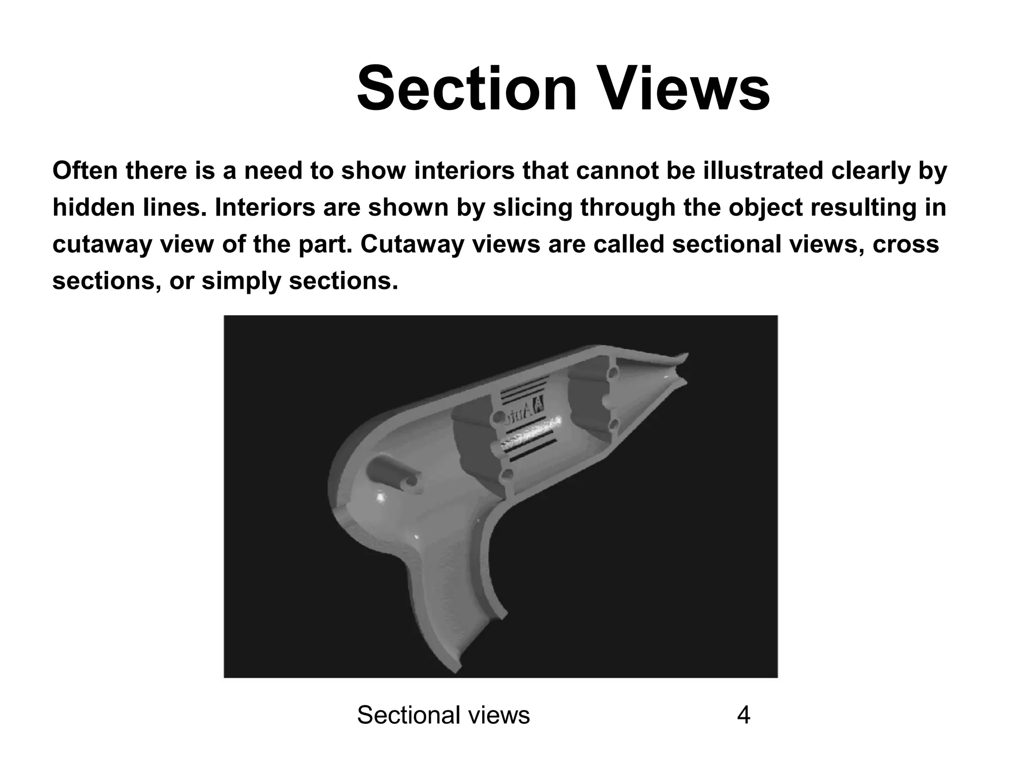
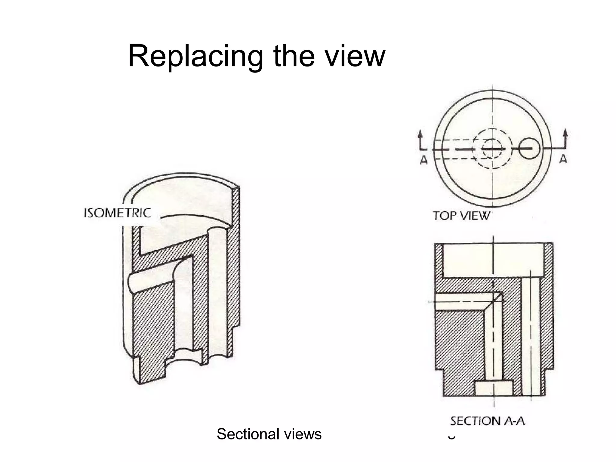
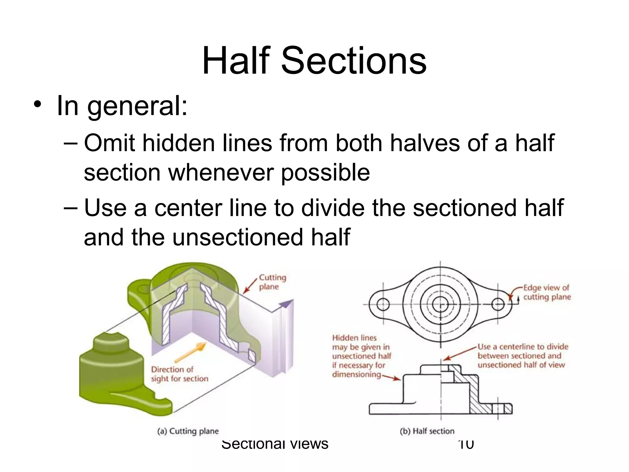
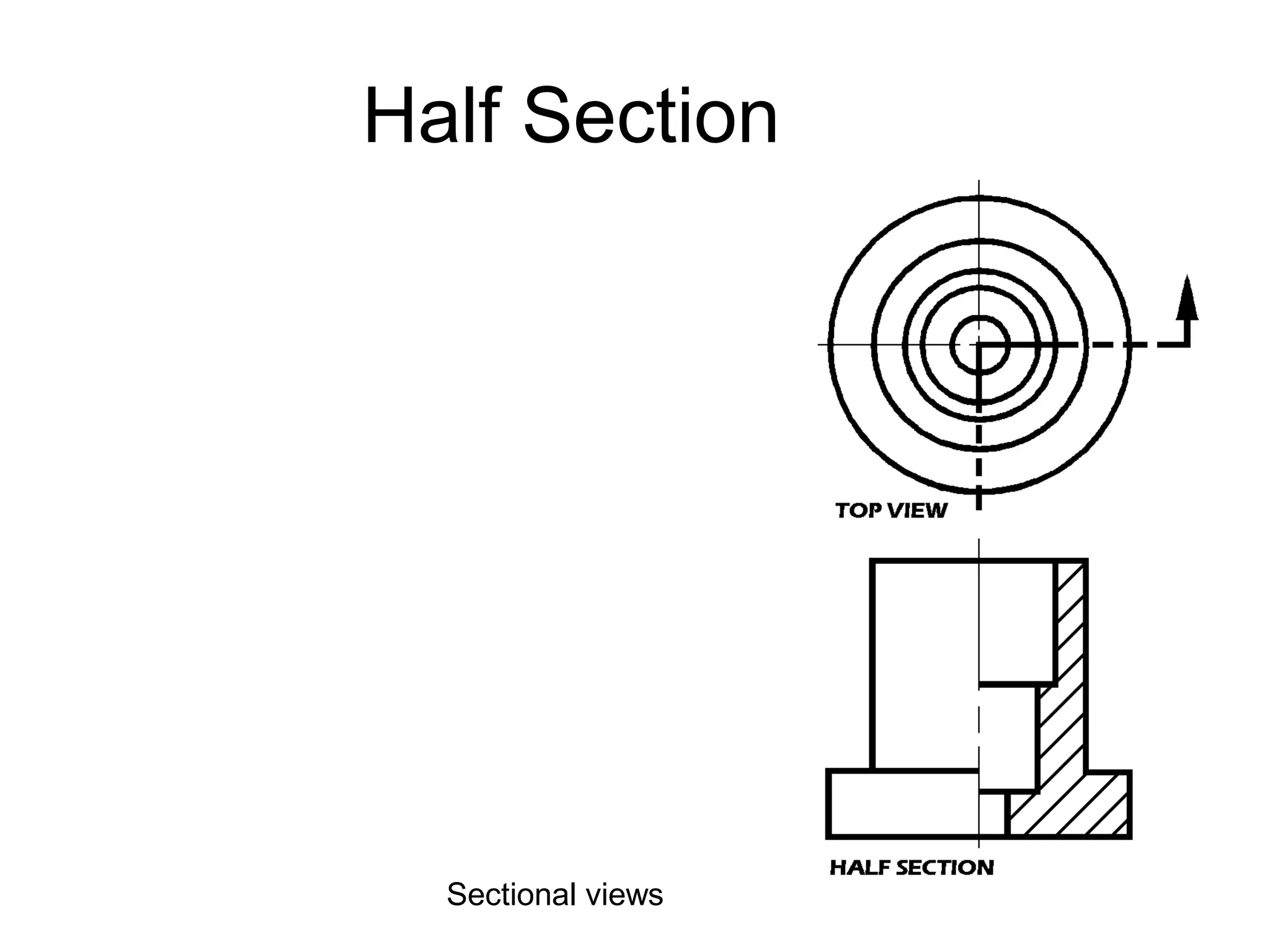
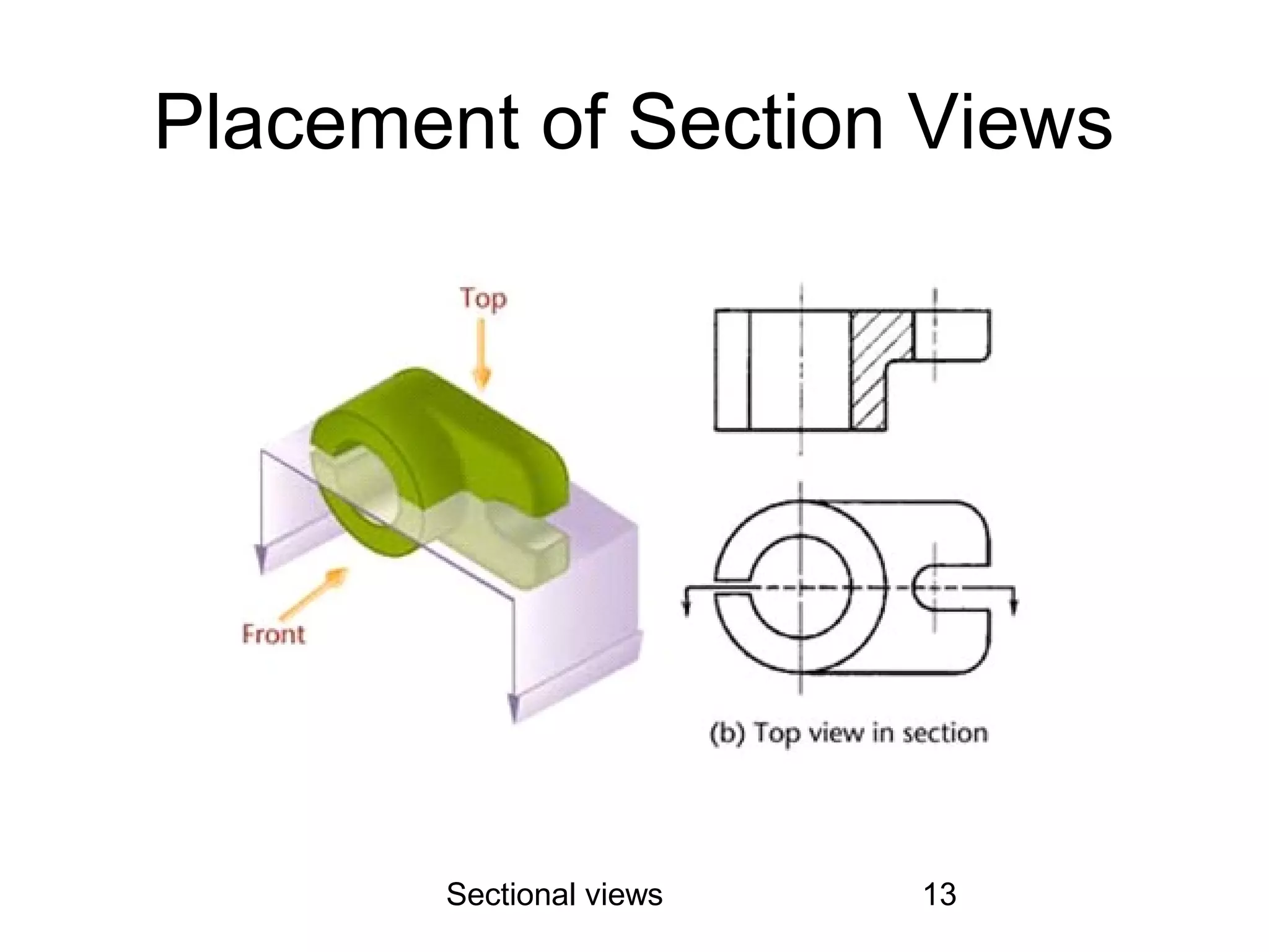
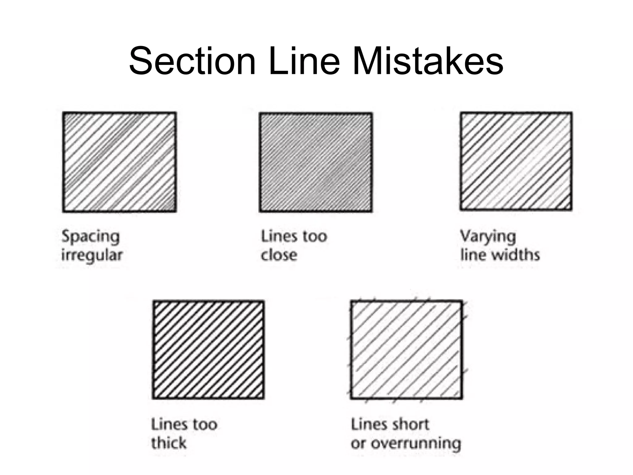
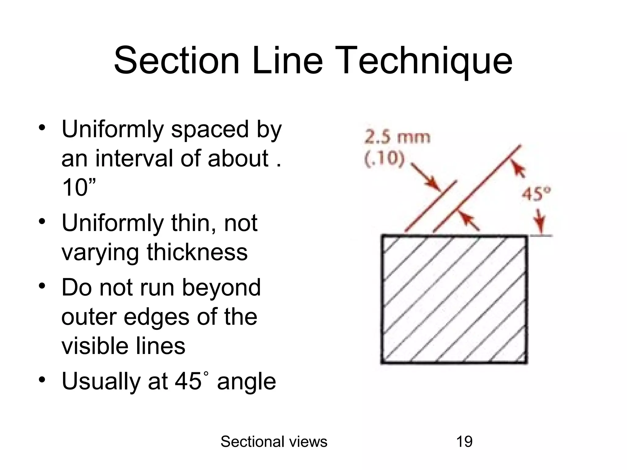
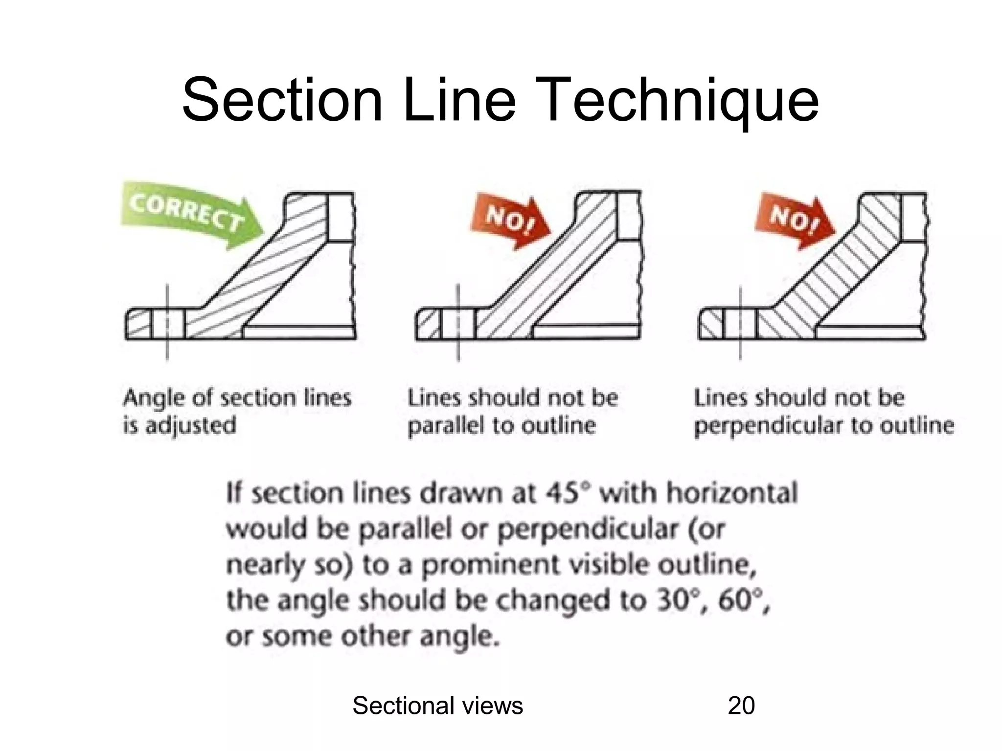
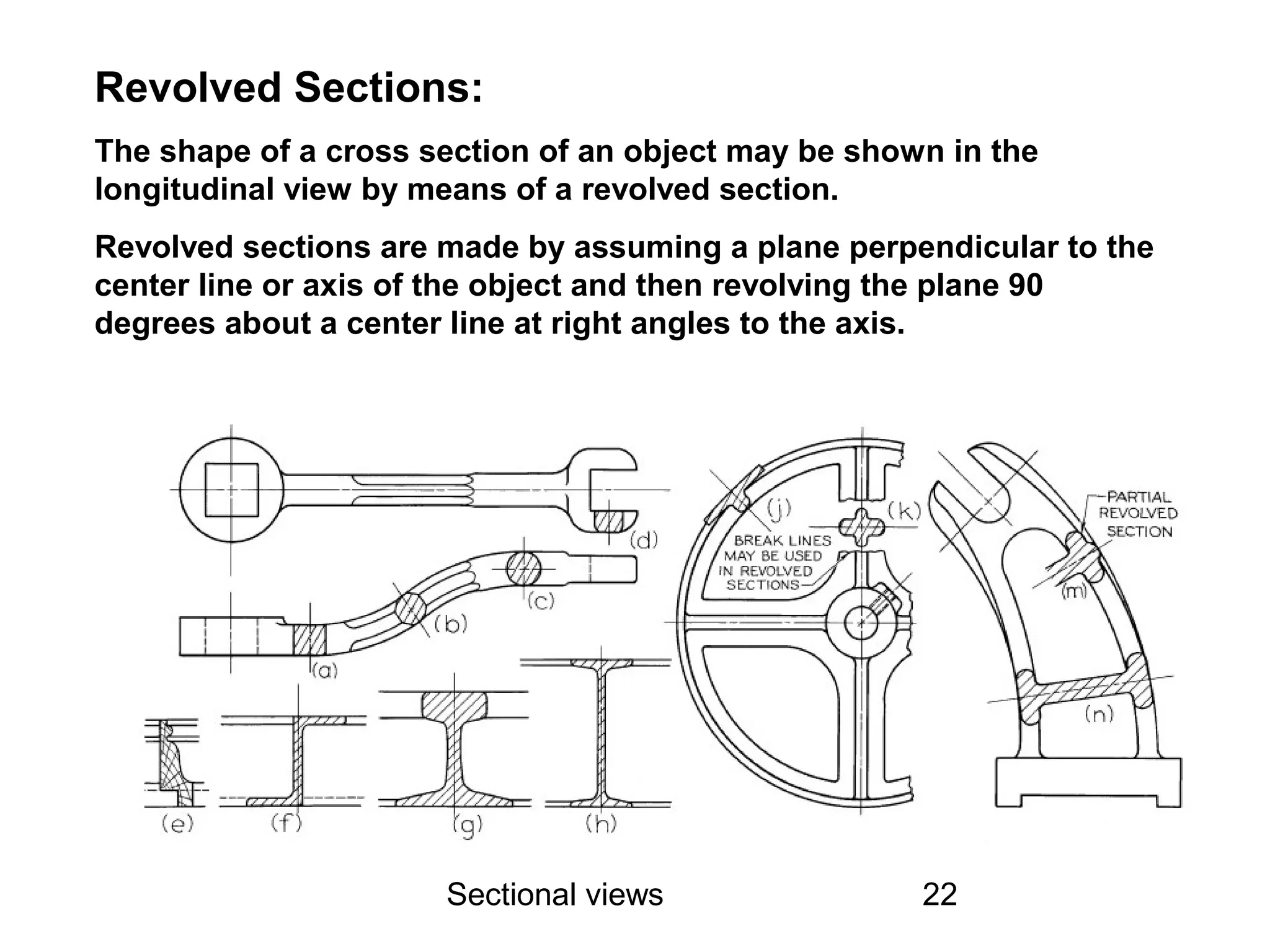
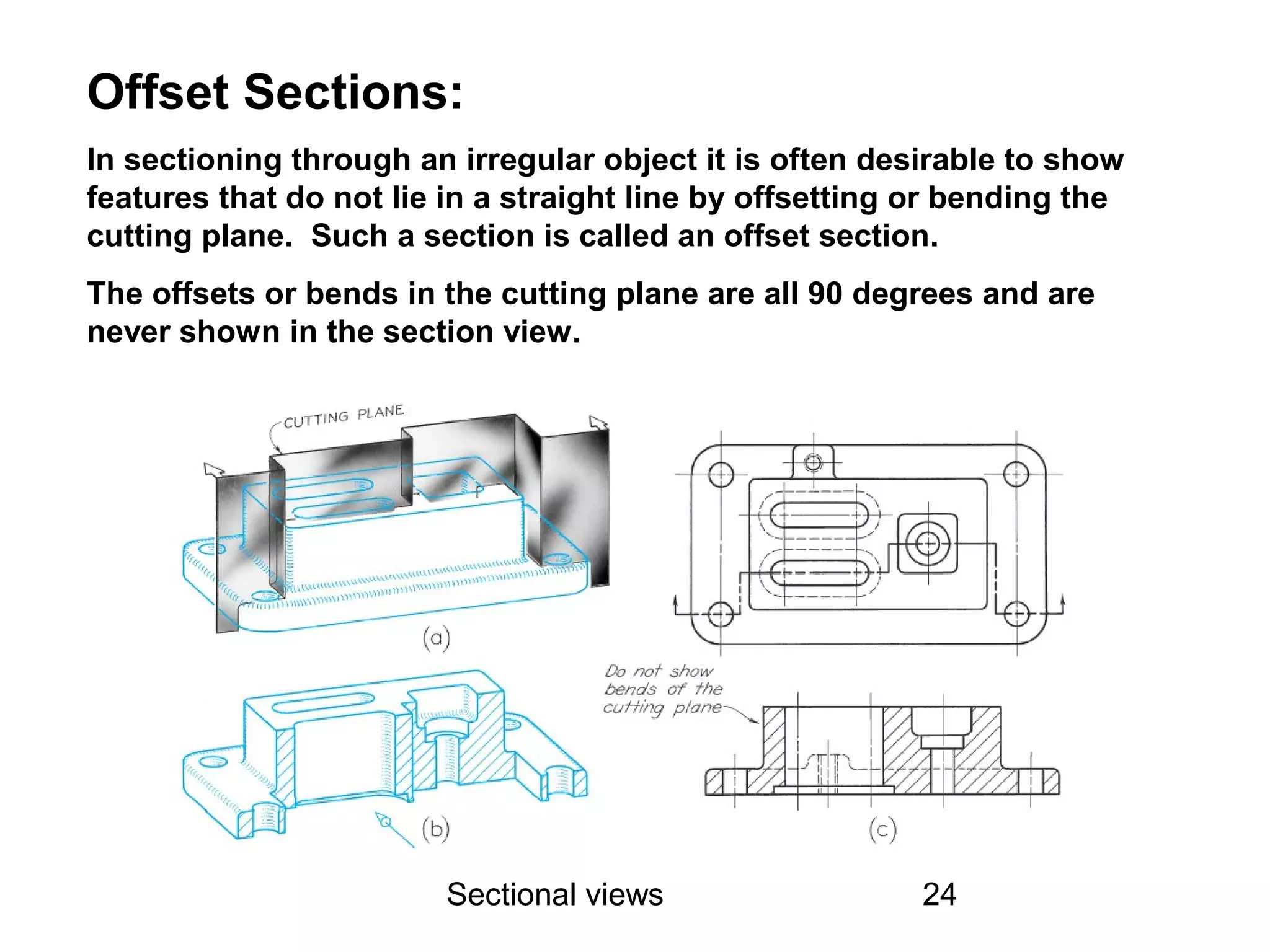
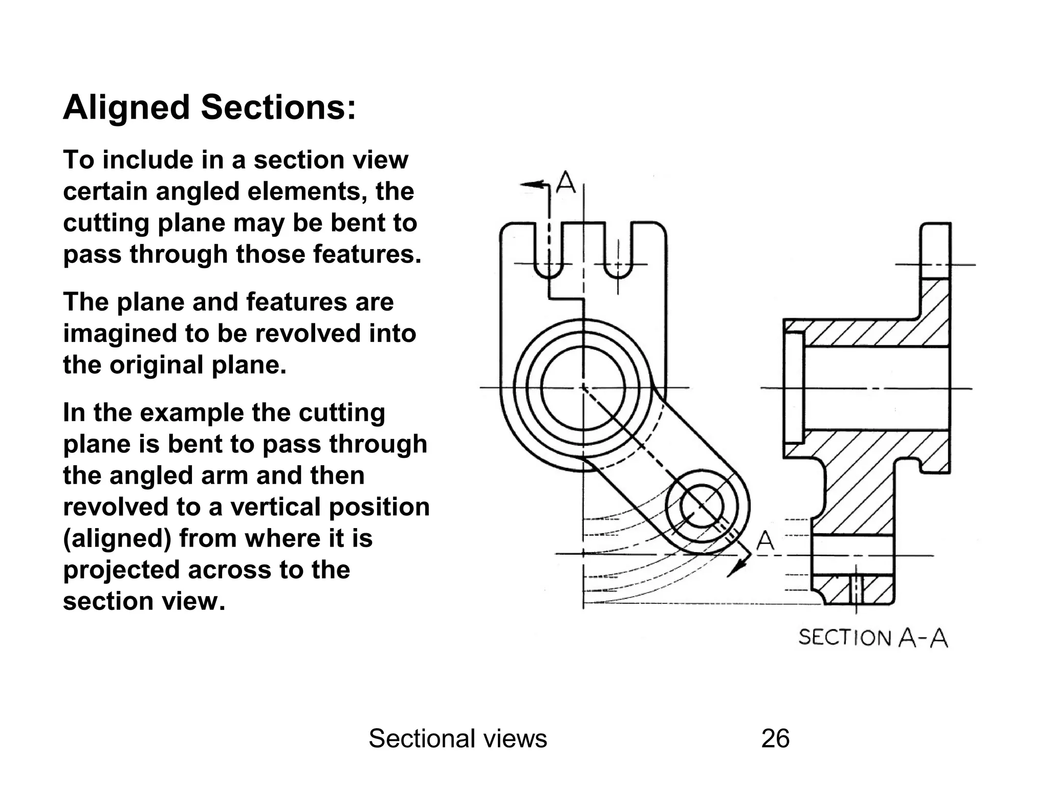
Sectional views 1
SECTIONING
Name of the Faculty: Shivraj Puggal
UID: 16125
E-mail ID:shivraj.16125@lpu.co.in
Sectional views 2
Issues to be addressed in the unit
• Types Sectional views
a) Full section
b) Half section
• Placement of Section Views
• Section Lining – Line Placement
• Section Line Mistakes
• Section Line Technique
Sectional views 3
What is a “Section View” ?
• A section view is a view used on a drawing to
show an area or hidden part of an object by
cutting away or removing some of that object.
• The cut line is called a “cutting plane”, and can
be done in several ways.
• The following slides will help show the several
methods or types of “section views”
Sectional views 4
Section Views
Often there is a need to show interiors that cannot be illustrated clearly by
hidden lines. Interiors are shown by slicing through the object resulting in
cutaway view of the part. Cutaway views are called sectional views, cross
sections, or simply sections.
Sectional views 5
Full Section
• In a full section, the cutting plane line
passes fully through the part.
• Normally a view is replaced with the full
section view.
• The section-lined areas are those portions
that have been in actual contact with the
cutting-plane.
Sectional views 6
Cutting Plane
Sectional views 7
Full Section
Sectional views 8
Replacing the view
Sectional views 9
Half Section
• Half Section is used to the exterior and
interior of the part in the same view.
• The cutting-plane line cuts halfway
through the part and removes one quarter
of the material.
• The line that separates the different types
(interior and exterior) may be a centerline
or a visible line.
Sectional views 10
Half Sections
• In general:
– Omit hidden lines from both halves of a half
section whenever possible
– Use a center line to divide the sectioned half
and the unsectioned half
Sectional views 11
Half Section
Sectional views 12
Placement of Section Views
• Section views can replace the normal top,
front, side, or other standard orthographic
view
Sectional views 13
Placement of Section Views
Sectional views 14
Section Lining – Line Placement
• Lines should never be parallel or
perpendicular to the object lines.
• If the outline of the object has 45 degree
lines, 30 or 60 degree lines should be
used.
• Assemblies with several parts should be
lined with varying angle section lines.
Sectional views 15
Section Lining – Line Placement
Sectional views 16
Section Line Mistakes
Sectional views 17
Section Line Mistakes
Sectional views 18
Cutting Plane Line Style
• Cutting lines are thick lines (0.7 mm)
• The preferred cutting plane line style is
made up of equal dashes ending in
arrowheads
– Another style uses alternating long dashes
and pairs of short dashes
Sectional views 19
Section Line Technique
• Uniformly spaced by
an interval of about .
10”
• Uniformly thin, not
varying thickness
• Do not run beyond
outer edges of the
visible lines
• Usually at 45˚ angle
Sectional views 20
Section Line Technique
Sectional views 21
Broken-Out Sections:
Often only a partial section of a view is needed to expose interior
shapes. Such a section, limited by an irregular break line is called a
broken-out section.
Sectional views 22
Revolved Sections:
The shape of a cross section of an object may be shown in the
longitudinal view by means of a revolved section.
Revolved sections are made by assuming a plane perpendicular to the
center line or axis of the object and then revolving the plane 90
degrees about a center line at right angles to the axis.
Sectional views 23
Removed
Sections:
A removed section is a
section view that is not
in direct projection
from the view
containing the cutting
plane.
Removed sections
should be labeled
Section A-A and
Section B-B,
corresponding to the
letters at the ends of
the cutting-plane line.
Removed sections
should be arranged in
alphabetical order from
left to right on the
drawing sheet
Sectional views 24
Offset Sections:
In sectioning through an irregular object it is often desirable to show
features that do not lie in a straight line by offsetting or bending the
cutting plane. Such a section is called an offset section.
The offsets or bends in the cutting plane are all 90 degrees and are
never shown in the section view.
Sectional views 25
Ribs in Sections:
To avoid a false impression
of thickness and solidity,
ribs, webs, gear teeth, and
other similar flat features are
not section lined even
though the cutting plane
passes through the feature.
In the example the cutting
plane A-A passes through
the vertical rib or web but
the rib or web is not section
lined (figure a).
Figure (b) is incorrect
because it gives a false
impression of thickness or
solidity.
Sectional views 26
Aligned Sections:
To include in a section view
certain angled elements, the
cutting plane may be bent to
pass through those features.
The plane and features are
imagined to be revolved into
the original plane.
In the example the cutting
plane is bent to pass through
the angled arm and then
revolved to a vertical position
(aligned) from where it is
projected across to the
section view.
Sectional views 27

sectional views

  • 1.
    Sectional views 1 SECTIONING Nameof the Faculty: Shivraj Puggal UID: 16125 E-mail ID:shivraj.16125@lpu.co.in
  • 2.
    Sectional views 2 Issuesto be addressed in the unit • Types Sectional views a) Full section b) Half section • Placement of Section Views • Section Lining – Line Placement • Section Line Mistakes • Section Line Technique
  • 3.
    Sectional views 3 Whatis a “Section View” ? • A section view is a view used on a drawing to show an area or hidden part of an object by cutting away or removing some of that object. • The cut line is called a “cutting plane”, and can be done in several ways. • The following slides will help show the several methods or types of “section views”
  • 4.
    Sectional views 4 SectionViews Often there is a need to show interiors that cannot be illustrated clearly by hidden lines. Interiors are shown by slicing through the object resulting in cutaway view of the part. Cutaway views are called sectional views, cross sections, or simply sections.
  • 5.
    Sectional views 5 FullSection • In a full section, the cutting plane line passes fully through the part. • Normally a view is replaced with the full section view. • The section-lined areas are those portions that have been in actual contact with the cutting-plane.
  • 6.
  • 7.
  • 8.
  • 9.
    Sectional views 9 HalfSection • Half Section is used to the exterior and interior of the part in the same view. • The cutting-plane line cuts halfway through the part and removes one quarter of the material. • The line that separates the different types (interior and exterior) may be a centerline or a visible line.
  • 10.
    Sectional views 10 HalfSections • In general: – Omit hidden lines from both halves of a half section whenever possible – Use a center line to divide the sectioned half and the unsectioned half
  • 11.
  • 12.
    Sectional views 12 Placementof Section Views • Section views can replace the normal top, front, side, or other standard orthographic view
  • 13.
  • 14.
    Sectional views 14 SectionLining – Line Placement • Lines should never be parallel or perpendicular to the object lines. • If the outline of the object has 45 degree lines, 30 or 60 degree lines should be used. • Assemblies with several parts should be lined with varying angle section lines.
  • 15.
    Sectional views 15 SectionLining – Line Placement
  • 16.
  • 17.
  • 18.
    Sectional views 18 CuttingPlane Line Style • Cutting lines are thick lines (0.7 mm) • The preferred cutting plane line style is made up of equal dashes ending in arrowheads – Another style uses alternating long dashes and pairs of short dashes
  • 19.
    Sectional views 19 SectionLine Technique • Uniformly spaced by an interval of about . 10” • Uniformly thin, not varying thickness • Do not run beyond outer edges of the visible lines • Usually at 45˚ angle
  • 20.
  • 21.
    Sectional views 21 Broken-OutSections: Often only a partial section of a view is needed to expose interior shapes. Such a section, limited by an irregular break line is called a broken-out section.
  • 22.
    Sectional views 22 RevolvedSections: The shape of a cross section of an object may be shown in the longitudinal view by means of a revolved section. Revolved sections are made by assuming a plane perpendicular to the center line or axis of the object and then revolving the plane 90 degrees about a center line at right angles to the axis.
  • 23.
    Sectional views 23 Removed Sections: Aremoved section is a section view that is not in direct projection from the view containing the cutting plane. Removed sections should be labeled Section A-A and Section B-B, corresponding to the letters at the ends of the cutting-plane line. Removed sections should be arranged in alphabetical order from left to right on the drawing sheet
  • 24.
    Sectional views 24 OffsetSections: In sectioning through an irregular object it is often desirable to show features that do not lie in a straight line by offsetting or bending the cutting plane. Such a section is called an offset section. The offsets or bends in the cutting plane are all 90 degrees and are never shown in the section view.
  • 25.
    Sectional views 25 Ribsin Sections: To avoid a false impression of thickness and solidity, ribs, webs, gear teeth, and other similar flat features are not section lined even though the cutting plane passes through the feature. In the example the cutting plane A-A passes through the vertical rib or web but the rib or web is not section lined (figure a). Figure (b) is incorrect because it gives a false impression of thickness or solidity.
  • 26.
    Sectional views 26 AlignedSections: To include in a section view certain angled elements, the cutting plane may be bent to pass through those features. The plane and features are imagined to be revolved into the original plane. In the example the cutting plane is bent to pass through the angled arm and then revolved to a vertical position (aligned) from where it is projected across to the section view.
  • 27.