SlideShare a Scribd company logo
Engineering Drawing
Adnan Aslam B.Sc. Mechanical Engineering HITEC University Taxila, Pakistan
Dimensioning:
The purpose of dimensioning is to provide clear and complete description of an object.
A complete set of dimensions will permit only one interpretation needed to construct the
part.
Dimensioning should follow these guidelines.
 Accuracy: correct values must be given
 Clearness: dimensions must be placed in appropriate positions
 Completeness: nothing must be left out, and nothing duplicated
 Readability: the appropriate line quality must be used for legibility
 The dimension line is a thin line, broken in the middle to allow the placement of
the dimension value, with arrowheads at each end. For an arrowhead, the length is
roughly three times the width.
Engineering Drawing
Adnan Aslam B.Sc. Mechanical Engineering HITEC University Taxila, Pakistan
 A leader is a thin line used to connect a dimension with a particular area. When
there is limited space, a heavy black dot may be substituted for the arrows.
Dimensioning System
Aligned System Unidirectional System
 Dimensions are placed perpendicular
to dimension lines.
 Horizontal and inclined dimensions
can be read from the bottom of the
drawing.
 Vertical lines can be read from the
right hand side of the drawing.
 Dimensions are always placed
vertically.
 All dimensions can be read from the
bottom of the drawing.
 Vertical and inclined dimensions are
placed at the middle of dimension
lines by breaking them.
Engineering Drawing
Adnan Aslam B.Sc. Mechanical Engineering HITEC University Taxila, Pakistan
Rules for dimensioning:
 Between any two extension lines there must be only one dimension.
 All the dimensions should be placed outside the views whenever possible
 All the dimensions must be using a single dimensioning system
 Same units must be used for all dimensions
 Give every dimension and avoid duplication
 Avoid using outlines and center lines for Dimensions
Engineering Drawing
Adnan Aslam B.Sc. Mechanical Engineering HITEC University Taxila, Pakistan
 When dimensions are to be placed inside a sectioned area, leave a blank space for the
dimensions
 Avoid dimensioning hidden lines
 If space between two lines is too narrow to mark then use
– Centre dimensioning
– Side dimensioning
– Leader dimensioning
 For dimensioning in series, adopt one of the following
 Chain dimensioning
 Parallel dimensioning
 Combined dimensioning
 Smaller dimensions should always be placed nearer the view.
 Dimension lines should not cross each other.
 The dimensions should be placed on the face that describes the feature most clearly.
Engineering Drawing
Adnan Aslam B.Sc. Mechanical Engineering HITEC University Taxila, Pakistan
Dimensioning of Circular Features:
 Dimension circles by giving diameters
 Dimension holes in views in which they appear as circles
 Dimension one hole if there are multiple holes of same diameter
 Arc should be dimensioned by giving its radius
 Cylindrical features should be dimensioned by giving their diameters.
 Spherical features may be dimensioned by giving either the radius or diameter of a
sphere
Engineering Drawing
Adnan Aslam B.Sc. Mechanical Engineering HITEC University Taxila, Pakistan
Lettering:
The word letter is used for alphabet, numeral, symbol, punctuation marks etc.
 The text on drawings must be neat and easy to read.
 The height of all the letters in one line should be the same.
 Draw letters as simple as possible
 Draw letters symmetrical about the vertical or horizontal axis whenever possible.
 Asymmetric letters like F,R,Z etc. may be drawn as they are
 Round off sharp corners wherever necessary.e.g. D, P, S etc.
 Use 10mm for Titles
 Use 7mm for subtitles
 Use 5mm for notes/dimensions
Setting a Drawing Sheet:
 Ensure instruments and hand are clean
 Adjust your drawing table
 Place the drawing sheet on the table
 Keep sheet close to the top left corner of the board
 Use your T-square to properly align the sheet
 Use Adhesive tape to fasten the sheet to the Board.
 Drawing Margins and Title Block
 Draw a rectangular frame
 Space of 10mm(0.5 in.) for each side
 Use the left and bottom lines as reference lines
 Title block located at the bottom right corner of the sheet.
Dimensions of Title Block:
 Total Length 160mm
 Total Height 70mm
 Half-cell length: 80mm
 Quarter cell length: 40mm
 Change dimensions to equivalent inch system.
Engineering Drawing
Adnan Aslam B.Sc. Mechanical Engineering HITEC University Taxila, Pakistan
Projection:
An image or the act of obtaining an image is called projection.
Principle Planes:
 Horizontal Plane
 Vertical Plane
 Profile Plane (Side Plane)
 Auxiliary Plane.
Multi-View Orthographic Projection:
 Method Used for drawing two or more views of an object on the Principle planes
 Projectors are perpendicular to the plane of projection and parallel to each other
 Any one view gives only two dimensions
 Min two views required to get three dimensions.
 Commonly referred to as orthographic Projection.
Orthographic Views:
1) Front View 2) Top View 2) Side View 3) Rear View 4) Bottom View
5) Usually the front, top and one of the side views are drawn in orthographic
projections.
Engineering Drawing
Adnan Aslam B.Sc. Mechanical Engineering HITEC University Taxila, Pakistan
Angle of Projection:
• 1stAngle of Projection • 3rdAngle of Projection.
Projecting the Side View:
Following Techniques can be used to obtain side views from the front and top view
– Projection across Meter Line
– Projection through 450 Triangle

More Related Content

What's hot

Engineering Drawing: Chapter 07 dimensioning
Engineering Drawing: Chapter 07 dimensioningEngineering Drawing: Chapter 07 dimensioning
Engineering Drawing: Chapter 07 dimensioning
mokhtar
 
Engineering Drawing: Chapter 05 pictorial sketching
Engineering Drawing: Chapter 05 pictorial sketchingEngineering Drawing: Chapter 05 pictorial sketching
Engineering Drawing: Chapter 05 pictorial sketching
mokhtar
 
Anurag Arpan (PPT on AutoCAD )
Anurag Arpan (PPT on AutoCAD )Anurag Arpan (PPT on AutoCAD )
Anurag Arpan (PPT on AutoCAD )
Anurag Arpan
 

What's hot (20)

Chapter 03 orthographic projection
Chapter 03 orthographic projectionChapter 03 orthographic projection
Chapter 03 orthographic projection
 
Introduction to engineering graphics
Introduction to engineering graphicsIntroduction to engineering graphics
Introduction to engineering graphics
 
Engineering Drawing: Chapter 07 dimensioning
Engineering Drawing: Chapter 07 dimensioningEngineering Drawing: Chapter 07 dimensioning
Engineering Drawing: Chapter 07 dimensioning
 
Orthographic Projections
Orthographic ProjectionsOrthographic Projections
Orthographic Projections
 
sectional views
sectional viewssectional views
sectional views
 
Orthographic projection
Orthographic projectionOrthographic projection
Orthographic projection
 
Engineering drawing chapter 07 dimensioning.ppt
Engineering drawing chapter 07 dimensioning.pptEngineering drawing chapter 07 dimensioning.ppt
Engineering drawing chapter 07 dimensioning.ppt
 
Chapter 6 by lelis
Chapter 6 by lelisChapter 6 by lelis
Chapter 6 by lelis
 
Engineering drawing unit 1-snist
Engineering drawing unit 1-snistEngineering drawing unit 1-snist
Engineering drawing unit 1-snist
 
Introduction to engineering graphics
Introduction to engineering graphicsIntroduction to engineering graphics
Introduction to engineering graphics
 
Engineering Drawing: Chapter 05 pictorial sketching
Engineering Drawing: Chapter 05 pictorial sketchingEngineering Drawing: Chapter 05 pictorial sketching
Engineering Drawing: Chapter 05 pictorial sketching
 
ENGINEERING GRAPHICS
ENGINEERING GRAPHICSENGINEERING GRAPHICS
ENGINEERING GRAPHICS
 
Engineering Drawing basics.ppt
Engineering Drawing basics.pptEngineering Drawing basics.ppt
Engineering Drawing basics.ppt
 
Auxiliary views
Auxiliary viewsAuxiliary views
Auxiliary views
 
Lecture iii orthographic projection
Lecture iii   orthographic projectionLecture iii   orthographic projection
Lecture iii orthographic projection
 
Isometric projection
Isometric projectionIsometric projection
Isometric projection
 
Isometric projections
Isometric projectionsIsometric projections
Isometric projections
 
Basic introduction to Engineering Drawing
Basic introduction to Engineering DrawingBasic introduction to Engineering Drawing
Basic introduction to Engineering Drawing
 
Anurag Arpan (PPT on AutoCAD )
Anurag Arpan (PPT on AutoCAD )Anurag Arpan (PPT on AutoCAD )
Anurag Arpan (PPT on AutoCAD )
 
Engineering graphics basics
Engineering graphics basics Engineering graphics basics
Engineering graphics basics
 

Viewers also liked

Why Civil Engineering is Best
Why Civil Engineering is BestWhy Civil Engineering is Best
Why Civil Engineering is Best
Rahul Chavda
 
Engineering Drawing: Chapter 01 introduction
Engineering Drawing: Chapter 01 introductionEngineering Drawing: Chapter 01 introduction
Engineering Drawing: Chapter 01 introduction
mokhtar
 
Civil engineering powerpoint
Civil engineering powerpointCivil engineering powerpoint
Civil engineering powerpoint
chrisminer01
 

Viewers also liked (9)

Introduction to Civil engineering drawing
Introduction to Civil engineering drawingIntroduction to Civil engineering drawing
Introduction to Civil engineering drawing
 
56 . Farmer field school (main activities carried out by farmers during an ...
56   . Farmer field school (main activities carried out by farmers during an ...56   . Farmer field school (main activities carried out by farmers during an ...
56 . Farmer field school (main activities carried out by farmers during an ...
 
Why Civil Engineering is Best
Why Civil Engineering is BestWhy Civil Engineering is Best
Why Civil Engineering is Best
 
Civil Engineering
Civil EngineeringCivil Engineering
Civil Engineering
 
Introduction to Civil Engineering
Introduction to Civil EngineeringIntroduction to Civil Engineering
Introduction to Civil Engineering
 
Engineering Drawing
Engineering DrawingEngineering Drawing
Engineering Drawing
 
Engineering Drawing: Chapter 01 introduction
Engineering Drawing: Chapter 01 introductionEngineering Drawing: Chapter 01 introduction
Engineering Drawing: Chapter 01 introduction
 
Civil engineering
Civil engineeringCivil engineering
Civil engineering
 
Civil engineering powerpoint
Civil engineering powerpointCivil engineering powerpoint
Civil engineering powerpoint
 

Similar to Basics Of Engineering Drawing (Dimensioning,Projections,Principle Views)

Similar to Basics Of Engineering Drawing (Dimensioning,Projections,Principle Views) (20)

practical geometry
practical geometrypractical geometry
practical geometry
 
Dimensioning.pdf
Dimensioning.pdfDimensioning.pdf
Dimensioning.pdf
 
Engineering drawing
Engineering drawingEngineering drawing
Engineering drawing
 
Notes-Engineering-Graphics-and-Design-1-.pdf
Notes-Engineering-Graphics-and-Design-1-.pdfNotes-Engineering-Graphics-and-Design-1-.pdf
Notes-Engineering-Graphics-and-Design-1-.pdf
 
Unit-1.ppt
Unit-1.pptUnit-1.ppt
Unit-1.ppt
 
Unit-1.ppt
Unit-1.pptUnit-1.ppt
Unit-1.ppt
 
Drawing reading and measurements
Drawing reading and measurementsDrawing reading and measurements
Drawing reading and measurements
 
Computer Aided Engineering Drawing 20ME12P DTE Karnataka
Computer Aided Engineering Drawing 20ME12P DTE KarnatakaComputer Aided Engineering Drawing 20ME12P DTE Karnataka
Computer Aided Engineering Drawing 20ME12P DTE Karnataka
 
CIVIL Engineering Drawing by haseeb muhammad
CIVIL Engineering Drawing by haseeb muhammadCIVIL Engineering Drawing by haseeb muhammad
CIVIL Engineering Drawing by haseeb muhammad
 
Types of Technical & Engineering Drawing Lines and Their Uses
Types of Technical & Engineering Drawing Lines and Their UsesTypes of Technical & Engineering Drawing Lines and Their Uses
Types of Technical & Engineering Drawing Lines and Their Uses
 
Graphic representation of technical projects
Graphic representation of technical projectsGraphic representation of technical projects
Graphic representation of technical projects
 
First and third angle projection
First and third angle projectionFirst and third angle projection
First and third angle projection
 
Introduction to engineering graphics
Introduction to engineering graphics Introduction to engineering graphics
Introduction to engineering graphics
 
01 graphic representation
01 graphic representation01 graphic representation
01 graphic representation
 
W1-Introduction to ED [Autosaved].pptx
W1-Introduction to ED [Autosaved].pptxW1-Introduction to ED [Autosaved].pptx
W1-Introduction to ED [Autosaved].pptx
 
Lecture week 5
Lecture week 5Lecture week 5
Lecture week 5
 
Lecture week 5
Lecture week 5Lecture week 5
Lecture week 5
 
Enggdrg 11
Enggdrg 11Enggdrg 11
Enggdrg 11
 
Enggdrg 11
Enggdrg 11Enggdrg 11
Enggdrg 11
 
All dimensioning system
All dimensioning systemAll dimensioning system
All dimensioning system
 

More from Adnan Aslam

More from Adnan Aslam (18)

Water purification Techniques
Water purification TechniquesWater purification Techniques
Water purification Techniques
 
Anti Lock Breaking System
Anti Lock Breaking SystemAnti Lock Breaking System
Anti Lock Breaking System
 
IRFAN_UL_QURAN (The 4th & Secure & Last One)
IRFAN_UL_QURAN (The 4th & Secure & Last One)IRFAN_UL_QURAN (The 4th & Secure & Last One)
IRFAN_UL_QURAN (The 4th & Secure & Last One)
 
Solutions Manual for machine design by khurmi and Gupta
Solutions Manual for machine design by khurmi and GuptaSolutions Manual for machine design by khurmi and Gupta
Solutions Manual for machine design by khurmi and Gupta
 
Open channel flow
Open channel flowOpen channel flow
Open channel flow
 
Jet engine thermodynamics
Jet engine thermodynamicsJet engine thermodynamics
Jet engine thermodynamics
 
Atkinson cycle (Atkinson cycle Engines)
Atkinson cycle (Atkinson cycle Engines)Atkinson cycle (Atkinson cycle Engines)
Atkinson cycle (Atkinson cycle Engines)
 
Glass Industry(Visit to Gunj Glass Pvt.Ltd)
Glass Industry(Visit to Gunj Glass Pvt.Ltd)Glass Industry(Visit to Gunj Glass Pvt.Ltd)
Glass Industry(Visit to Gunj Glass Pvt.Ltd)
 
Water Desalination
Water DesalinationWater Desalination
Water Desalination
 
Child Labour
Child Labour Child Labour
Child Labour
 
Verification of 2nd Condition of Equilibrium
Verification of 2nd Condition of Equilibrium Verification of 2nd Condition of Equilibrium
Verification of 2nd Condition of Equilibrium
 
Second condition of equilibrium
Second condition of equilibriumSecond condition of equilibrium
Second condition of equilibrium
 
Future Of Transpotation
Future Of TranspotationFuture Of Transpotation
Future Of Transpotation
 
Local government of pakistan
Local government of pakistanLocal government of pakistan
Local government of pakistan
 
Thread terminology
Thread terminologyThread terminology
Thread terminology
 
Threads
ThreadsThreads
Threads
 
Paper Industry
Paper IndustryPaper Industry
Paper Industry
 
Paper industry
Paper industryPaper industry
Paper industry
 

Recently uploaded

Digital Signal Processing Lecture notes n.pdf
Digital Signal Processing Lecture notes n.pdfDigital Signal Processing Lecture notes n.pdf
Digital Signal Processing Lecture notes n.pdf
AbrahamGadissa
 
CFD Simulation of By-pass Flow in a HRSG module by R&R Consult.pptx
CFD Simulation of By-pass Flow in a HRSG module by R&R Consult.pptxCFD Simulation of By-pass Flow in a HRSG module by R&R Consult.pptx
CFD Simulation of By-pass Flow in a HRSG module by R&R Consult.pptx
R&R Consult
 
Fruit shop management system project report.pdf
Fruit shop management system project report.pdfFruit shop management system project report.pdf
Fruit shop management system project report.pdf
Kamal Acharya
 
Standard Reomte Control Interface - Neometrix
Standard Reomte Control Interface - NeometrixStandard Reomte Control Interface - Neometrix
Standard Reomte Control Interface - Neometrix
Neometrix_Engineering_Pvt_Ltd
 

Recently uploaded (20)

Scaling in conventional MOSFET for constant electric field and constant voltage
Scaling in conventional MOSFET for constant electric field and constant voltageScaling in conventional MOSFET for constant electric field and constant voltage
Scaling in conventional MOSFET for constant electric field and constant voltage
 
A CASE STUDY ON ONLINE TICKET BOOKING SYSTEM PROJECT.pdf
A CASE STUDY ON ONLINE TICKET BOOKING SYSTEM PROJECT.pdfA CASE STUDY ON ONLINE TICKET BOOKING SYSTEM PROJECT.pdf
A CASE STUDY ON ONLINE TICKET BOOKING SYSTEM PROJECT.pdf
 
Halogenation process of chemical process industries
Halogenation process of chemical process industriesHalogenation process of chemical process industries
Halogenation process of chemical process industries
 
HYDROPOWER - Hydroelectric power generation
HYDROPOWER - Hydroelectric power generationHYDROPOWER - Hydroelectric power generation
HYDROPOWER - Hydroelectric power generation
 
Arduino based vehicle speed tracker project
Arduino based vehicle speed tracker projectArduino based vehicle speed tracker project
Arduino based vehicle speed tracker project
 
A case study of cinema management system project report..pdf
A case study of cinema management system project report..pdfA case study of cinema management system project report..pdf
A case study of cinema management system project report..pdf
 
Digital Signal Processing Lecture notes n.pdf
Digital Signal Processing Lecture notes n.pdfDigital Signal Processing Lecture notes n.pdf
Digital Signal Processing Lecture notes n.pdf
 
Introduction to Casting Processes in Manufacturing
Introduction to Casting Processes in ManufacturingIntroduction to Casting Processes in Manufacturing
Introduction to Casting Processes in Manufacturing
 
CFD Simulation of By-pass Flow in a HRSG module by R&R Consult.pptx
CFD Simulation of By-pass Flow in a HRSG module by R&R Consult.pptxCFD Simulation of By-pass Flow in a HRSG module by R&R Consult.pptx
CFD Simulation of By-pass Flow in a HRSG module by R&R Consult.pptx
 
Cloud-Computing_CSE311_Computer-Networking CSE GUB BD - Shahidul.pptx
Cloud-Computing_CSE311_Computer-Networking CSE GUB BD - Shahidul.pptxCloud-Computing_CSE311_Computer-Networking CSE GUB BD - Shahidul.pptx
Cloud-Computing_CSE311_Computer-Networking CSE GUB BD - Shahidul.pptx
 
Electrostatic field in a coaxial transmission line
Electrostatic field in a coaxial transmission lineElectrostatic field in a coaxial transmission line
Electrostatic field in a coaxial transmission line
 
retail automation billing system ppt.pptx
retail automation billing system ppt.pptxretail automation billing system ppt.pptx
retail automation billing system ppt.pptx
 
Furniture showroom management system project.pdf
Furniture showroom management system project.pdfFurniture showroom management system project.pdf
Furniture showroom management system project.pdf
 
RESORT MANAGEMENT AND RESERVATION SYSTEM PROJECT REPORT.pdf
RESORT MANAGEMENT AND RESERVATION SYSTEM PROJECT REPORT.pdfRESORT MANAGEMENT AND RESERVATION SYSTEM PROJECT REPORT.pdf
RESORT MANAGEMENT AND RESERVATION SYSTEM PROJECT REPORT.pdf
 
KIT-601 Lecture Notes-UNIT-3.pdf Mining Data Stream
KIT-601 Lecture Notes-UNIT-3.pdf Mining Data StreamKIT-601 Lecture Notes-UNIT-3.pdf Mining Data Stream
KIT-601 Lecture Notes-UNIT-3.pdf Mining Data Stream
 
Quality defects in TMT Bars, Possible causes and Potential Solutions.
Quality defects in TMT Bars, Possible causes and Potential Solutions.Quality defects in TMT Bars, Possible causes and Potential Solutions.
Quality defects in TMT Bars, Possible causes and Potential Solutions.
 
Event Management System Vb Net Project Report.pdf
Event Management System Vb Net  Project Report.pdfEvent Management System Vb Net  Project Report.pdf
Event Management System Vb Net Project Report.pdf
 
The Benefits and Techniques of Trenchless Pipe Repair.pdf
The Benefits and Techniques of Trenchless Pipe Repair.pdfThe Benefits and Techniques of Trenchless Pipe Repair.pdf
The Benefits and Techniques of Trenchless Pipe Repair.pdf
 
Fruit shop management system project report.pdf
Fruit shop management system project report.pdfFruit shop management system project report.pdf
Fruit shop management system project report.pdf
 
Standard Reomte Control Interface - Neometrix
Standard Reomte Control Interface - NeometrixStandard Reomte Control Interface - Neometrix
Standard Reomte Control Interface - Neometrix
 

Basics Of Engineering Drawing (Dimensioning,Projections,Principle Views)

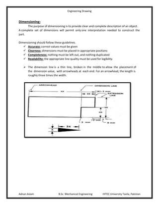
  • 1. Engineering Drawing Adnan Aslam B.Sc. Mechanical Engineering HITEC University Taxila, Pakistan Dimensioning: The purpose of dimensioning is to provide clear and complete description of an object. A complete set of dimensions will permit only one interpretation needed to construct the part. Dimensioning should follow these guidelines.  Accuracy: correct values must be given  Clearness: dimensions must be placed in appropriate positions  Completeness: nothing must be left out, and nothing duplicated  Readability: the appropriate line quality must be used for legibility  The dimension line is a thin line, broken in the middle to allow the placement of the dimension value, with arrowheads at each end. For an arrowhead, the length is roughly three times the width.
  • 2. Engineering Drawing Adnan Aslam B.Sc. Mechanical Engineering HITEC University Taxila, Pakistan  A leader is a thin line used to connect a dimension with a particular area. When there is limited space, a heavy black dot may be substituted for the arrows. Dimensioning System Aligned System Unidirectional System  Dimensions are placed perpendicular to dimension lines.  Horizontal and inclined dimensions can be read from the bottom of the drawing.  Vertical lines can be read from the right hand side of the drawing.  Dimensions are always placed vertically.  All dimensions can be read from the bottom of the drawing.  Vertical and inclined dimensions are placed at the middle of dimension lines by breaking them.
  • 3. Engineering Drawing Adnan Aslam B.Sc. Mechanical Engineering HITEC University Taxila, Pakistan Rules for dimensioning:  Between any two extension lines there must be only one dimension.  All the dimensions should be placed outside the views whenever possible  All the dimensions must be using a single dimensioning system  Same units must be used for all dimensions  Give every dimension and avoid duplication  Avoid using outlines and center lines for Dimensions
  • 4. Engineering Drawing Adnan Aslam B.Sc. Mechanical Engineering HITEC University Taxila, Pakistan  When dimensions are to be placed inside a sectioned area, leave a blank space for the dimensions  Avoid dimensioning hidden lines  If space between two lines is too narrow to mark then use – Centre dimensioning – Side dimensioning – Leader dimensioning  For dimensioning in series, adopt one of the following  Chain dimensioning  Parallel dimensioning  Combined dimensioning  Smaller dimensions should always be placed nearer the view.  Dimension lines should not cross each other.  The dimensions should be placed on the face that describes the feature most clearly.
  • 5. Engineering Drawing Adnan Aslam B.Sc. Mechanical Engineering HITEC University Taxila, Pakistan Dimensioning of Circular Features:  Dimension circles by giving diameters  Dimension holes in views in which they appear as circles  Dimension one hole if there are multiple holes of same diameter  Arc should be dimensioned by giving its radius  Cylindrical features should be dimensioned by giving their diameters.  Spherical features may be dimensioned by giving either the radius or diameter of a sphere
  • 6. Engineering Drawing Adnan Aslam B.Sc. Mechanical Engineering HITEC University Taxila, Pakistan Lettering: The word letter is used for alphabet, numeral, symbol, punctuation marks etc.  The text on drawings must be neat and easy to read.  The height of all the letters in one line should be the same.  Draw letters as simple as possible  Draw letters symmetrical about the vertical or horizontal axis whenever possible.  Asymmetric letters like F,R,Z etc. may be drawn as they are  Round off sharp corners wherever necessary.e.g. D, P, S etc.  Use 10mm for Titles  Use 7mm for subtitles  Use 5mm for notes/dimensions Setting a Drawing Sheet:  Ensure instruments and hand are clean  Adjust your drawing table  Place the drawing sheet on the table  Keep sheet close to the top left corner of the board  Use your T-square to properly align the sheet  Use Adhesive tape to fasten the sheet to the Board.  Drawing Margins and Title Block  Draw a rectangular frame  Space of 10mm(0.5 in.) for each side  Use the left and bottom lines as reference lines  Title block located at the bottom right corner of the sheet. Dimensions of Title Block:  Total Length 160mm  Total Height 70mm  Half-cell length: 80mm  Quarter cell length: 40mm  Change dimensions to equivalent inch system.
  • 7. Engineering Drawing Adnan Aslam B.Sc. Mechanical Engineering HITEC University Taxila, Pakistan Projection: An image or the act of obtaining an image is called projection. Principle Planes:  Horizontal Plane  Vertical Plane  Profile Plane (Side Plane)  Auxiliary Plane. Multi-View Orthographic Projection:  Method Used for drawing two or more views of an object on the Principle planes  Projectors are perpendicular to the plane of projection and parallel to each other  Any one view gives only two dimensions  Min two views required to get three dimensions.  Commonly referred to as orthographic Projection. Orthographic Views: 1) Front View 2) Top View 2) Side View 3) Rear View 4) Bottom View 5) Usually the front, top and one of the side views are drawn in orthographic projections.
  • 8. Engineering Drawing Adnan Aslam B.Sc. Mechanical Engineering HITEC University Taxila, Pakistan Angle of Projection: • 1stAngle of Projection • 3rdAngle of Projection. Projecting the Side View: Following Techniques can be used to obtain side views from the front and top view – Projection across Meter Line – Projection through 450 Triangle