Downloaded 7,020 times

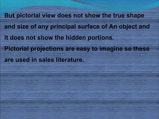


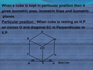
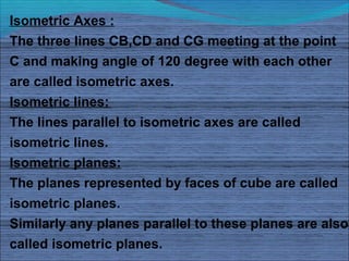

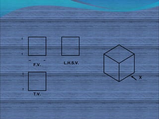

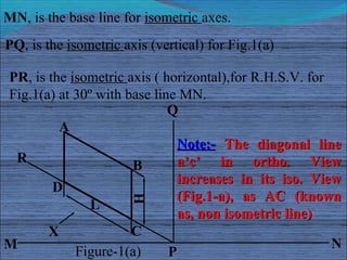


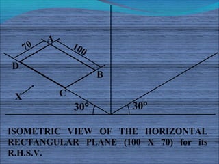


The document discusses isometric projections and isometric drawing. It begins by explaining the limitations of orthographic views and how isometric projections show all three dimensions of an object in a single view. It then defines the principles and types of projection, including orthographic, pictorial, axonometric, isometric, dimetric and trimetric. The remainder of the document focuses specifically on isometric projection, defining isometric axes, lines, planes and drawings. It provides examples of how to construct isometric views of various objects from their orthographic projections.