
Downloaded 117 times
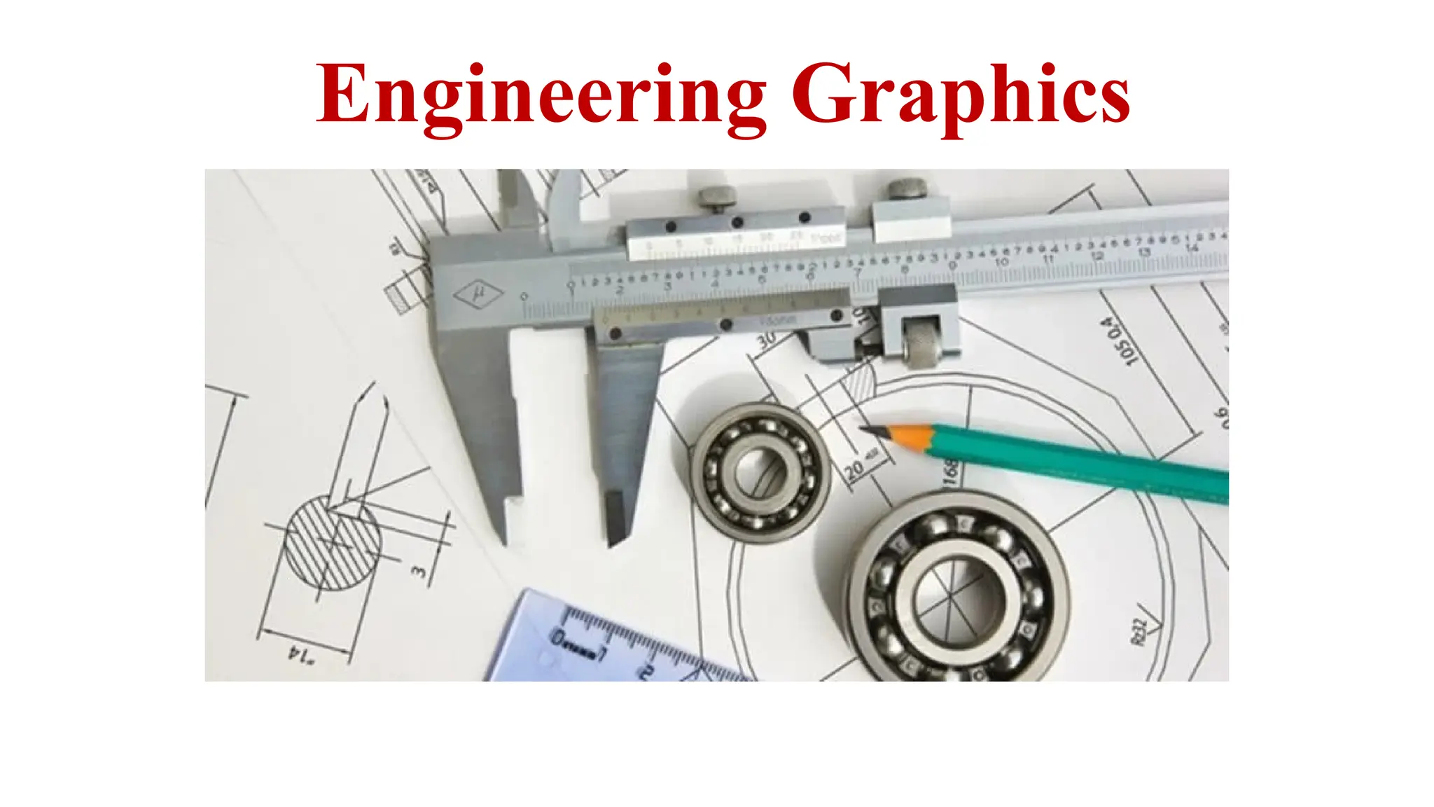
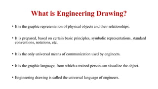
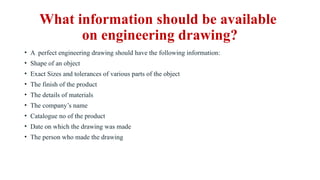
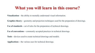


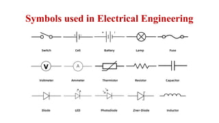


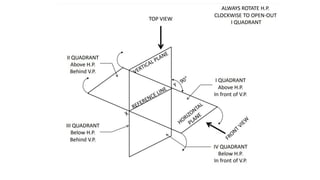
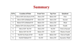
Engineering drawing is the graphic representation of physical objects, utilizing standardized symbols and conventions for universal communication among engineers. A complete engineering drawing should include essential details such as dimensions, materials, and identification specifics, while also following established methods and rules. The course covers visualization techniques, graphics theory, standard practices, tools, and dimensioning necessary for creating accurate engineering drawings.


![[Deck] What's New in Spark-Iceberg Integration via DSV2.pptx](https://cdn.slidesharecdn.com/ss_thumbnails/deckwhatsnewinspark-icebergintegrationviadsv2-260210005337-25955b12-thumbnail.jpg?width=640&height=640&fit=bounds)


