Downloaded 963 times
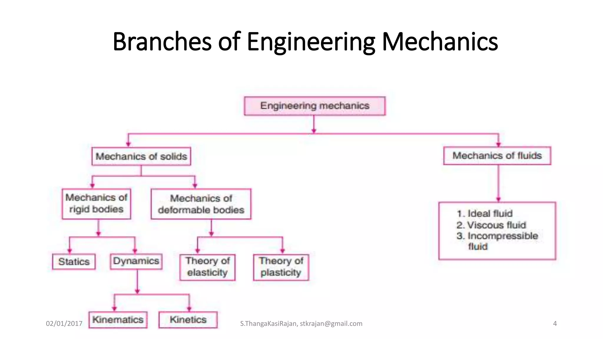
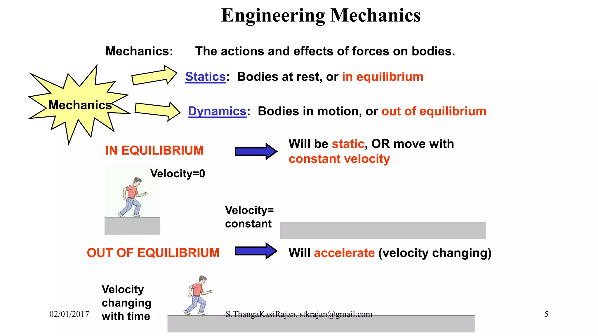
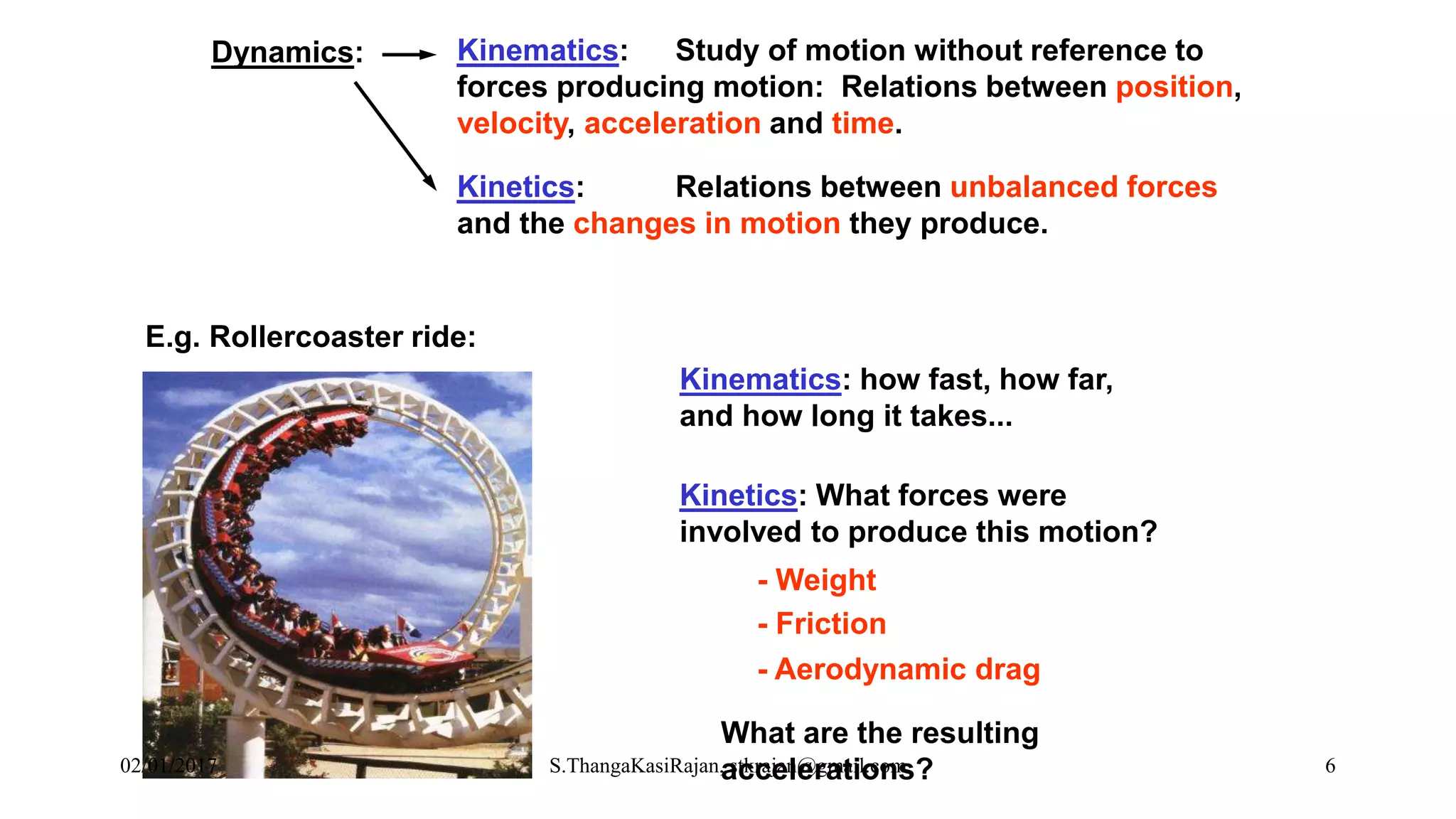
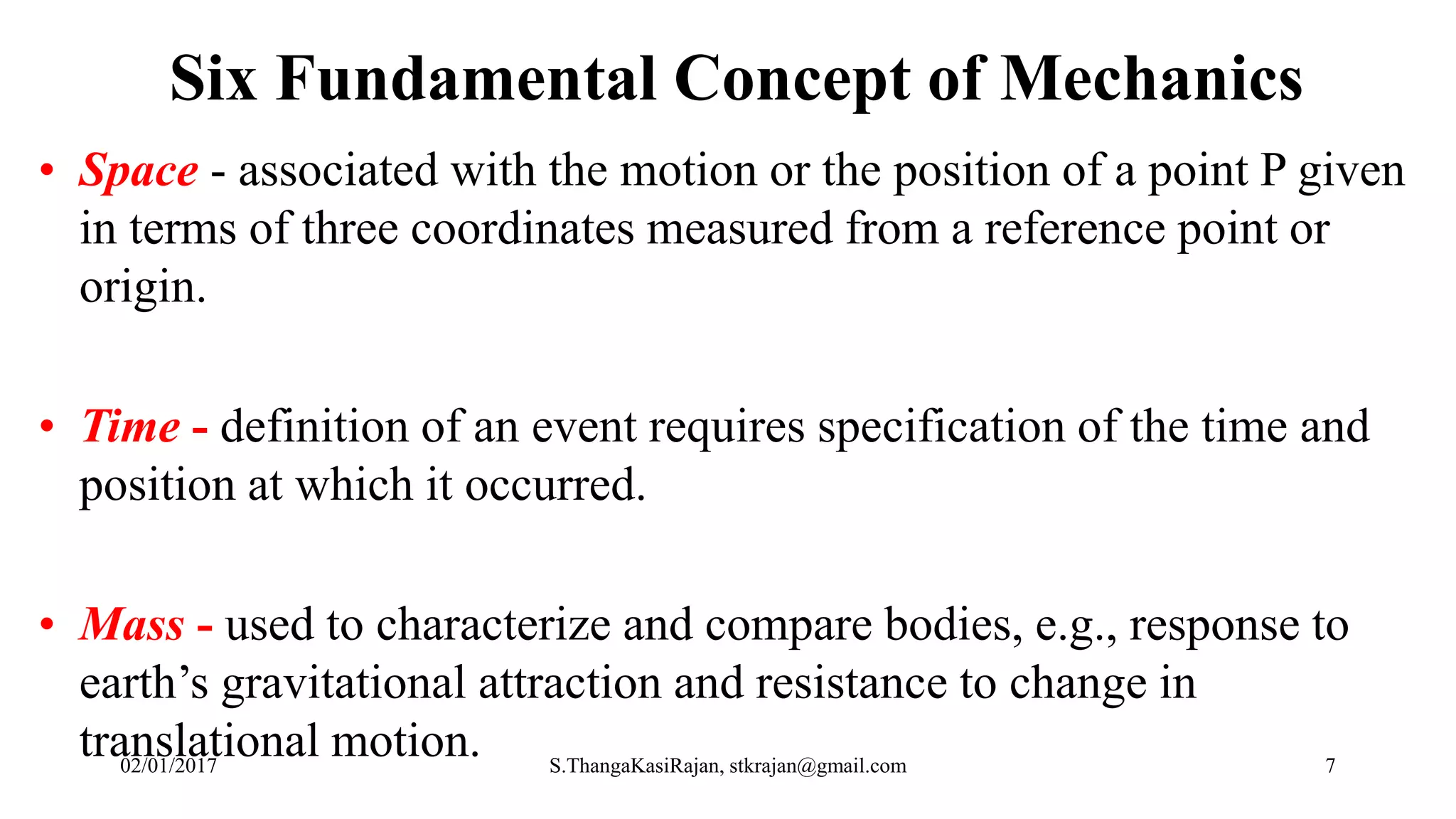
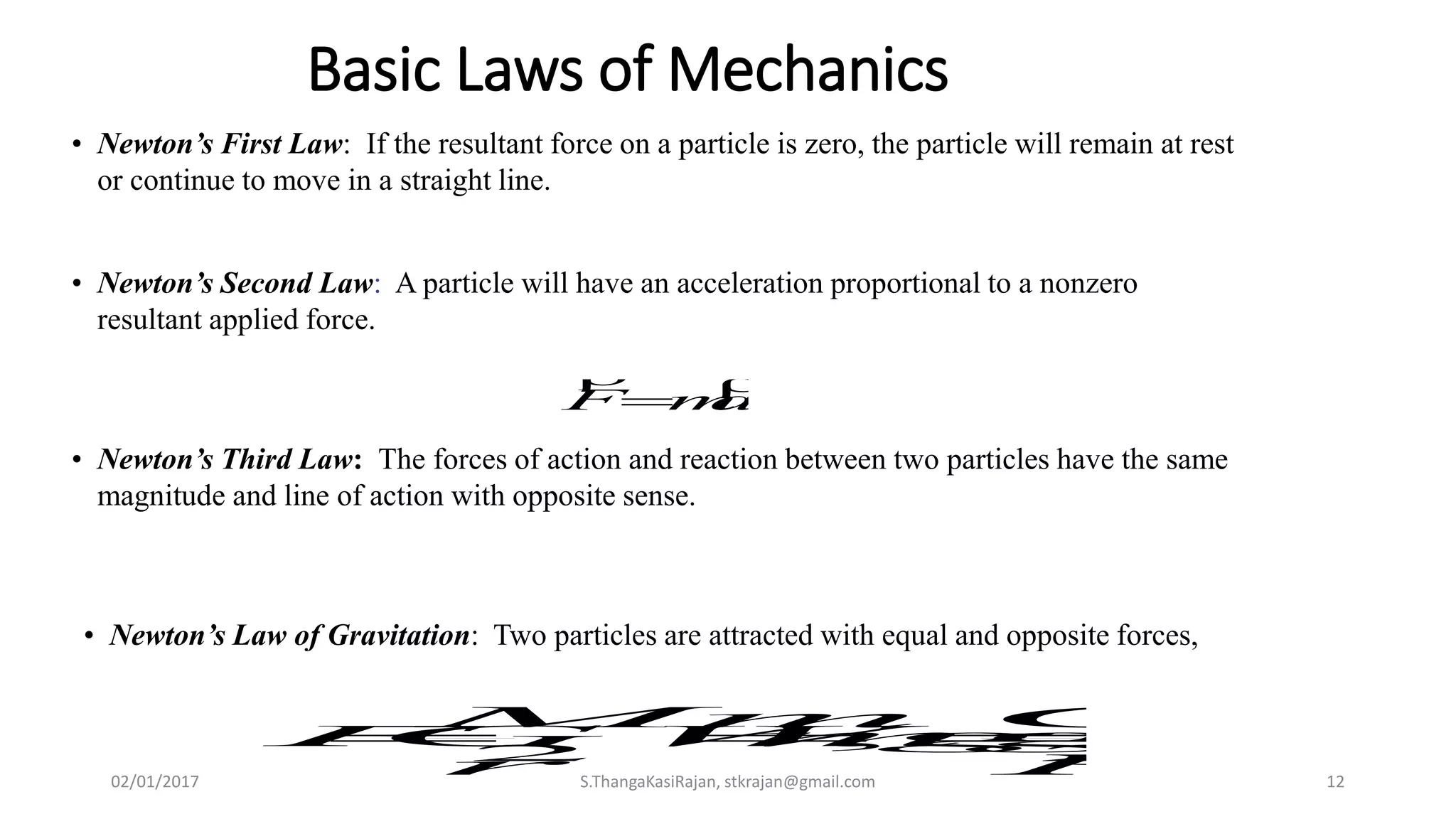
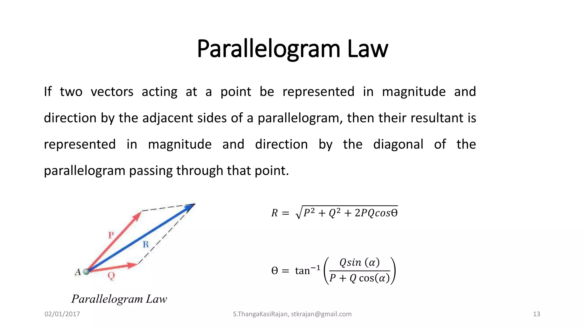
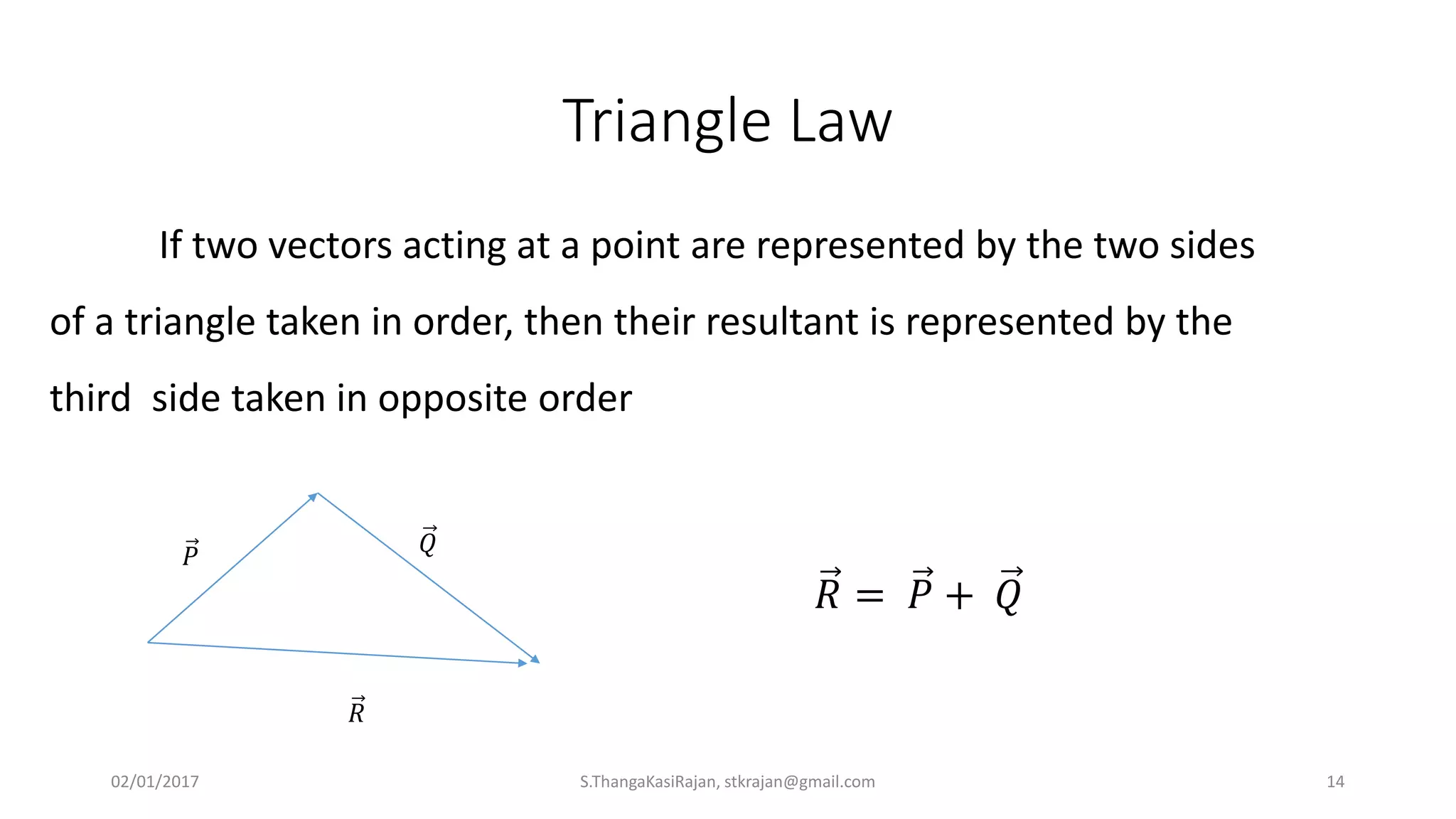
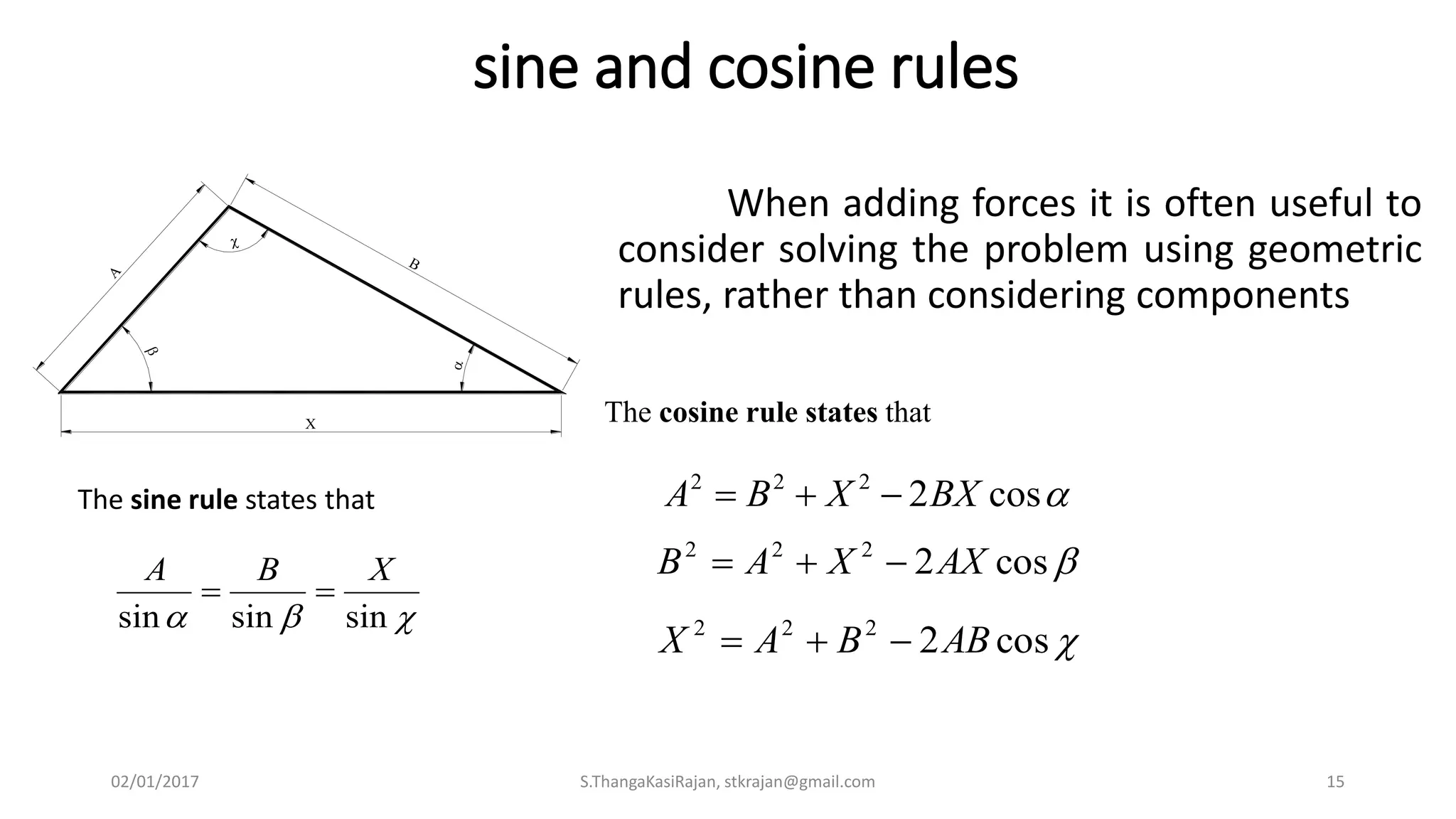
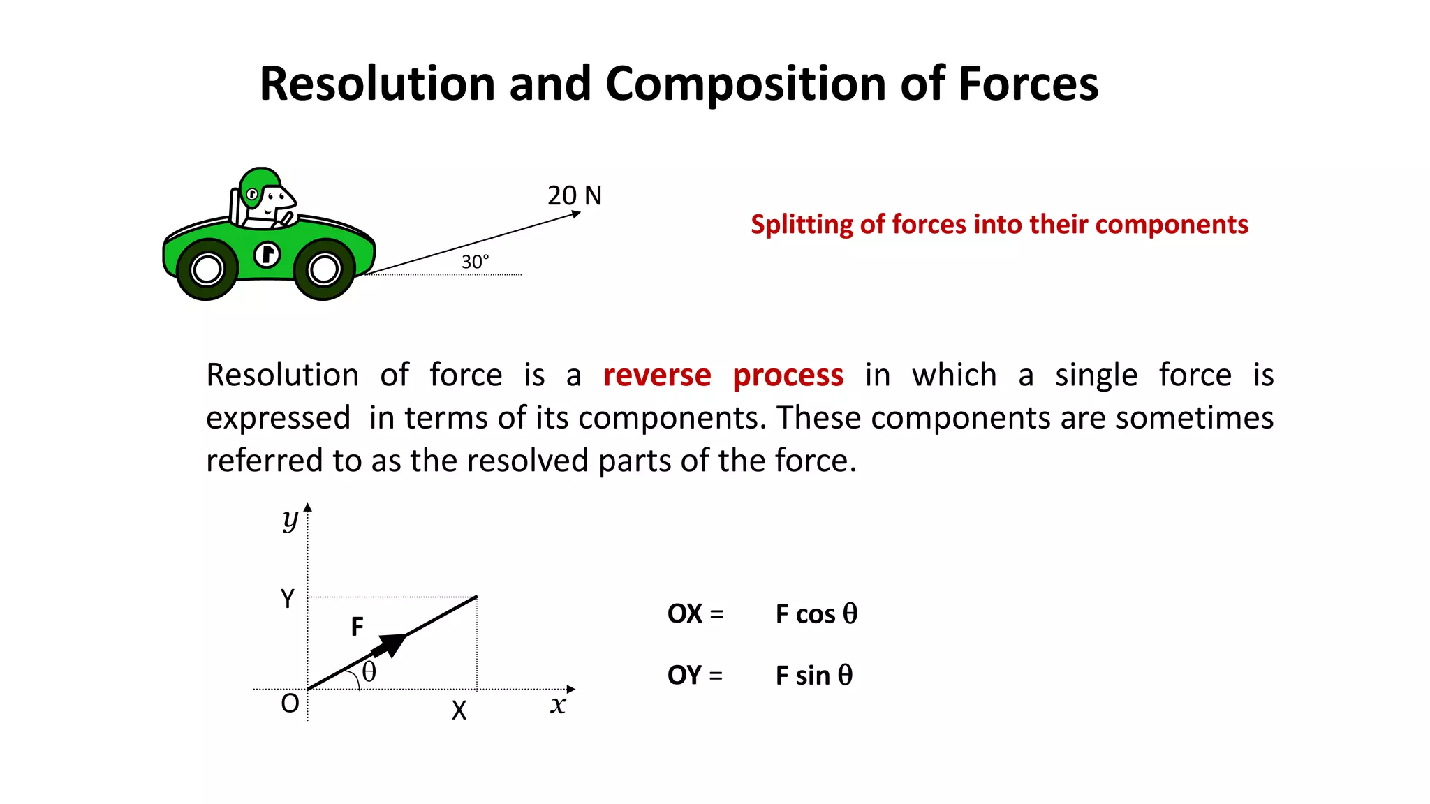
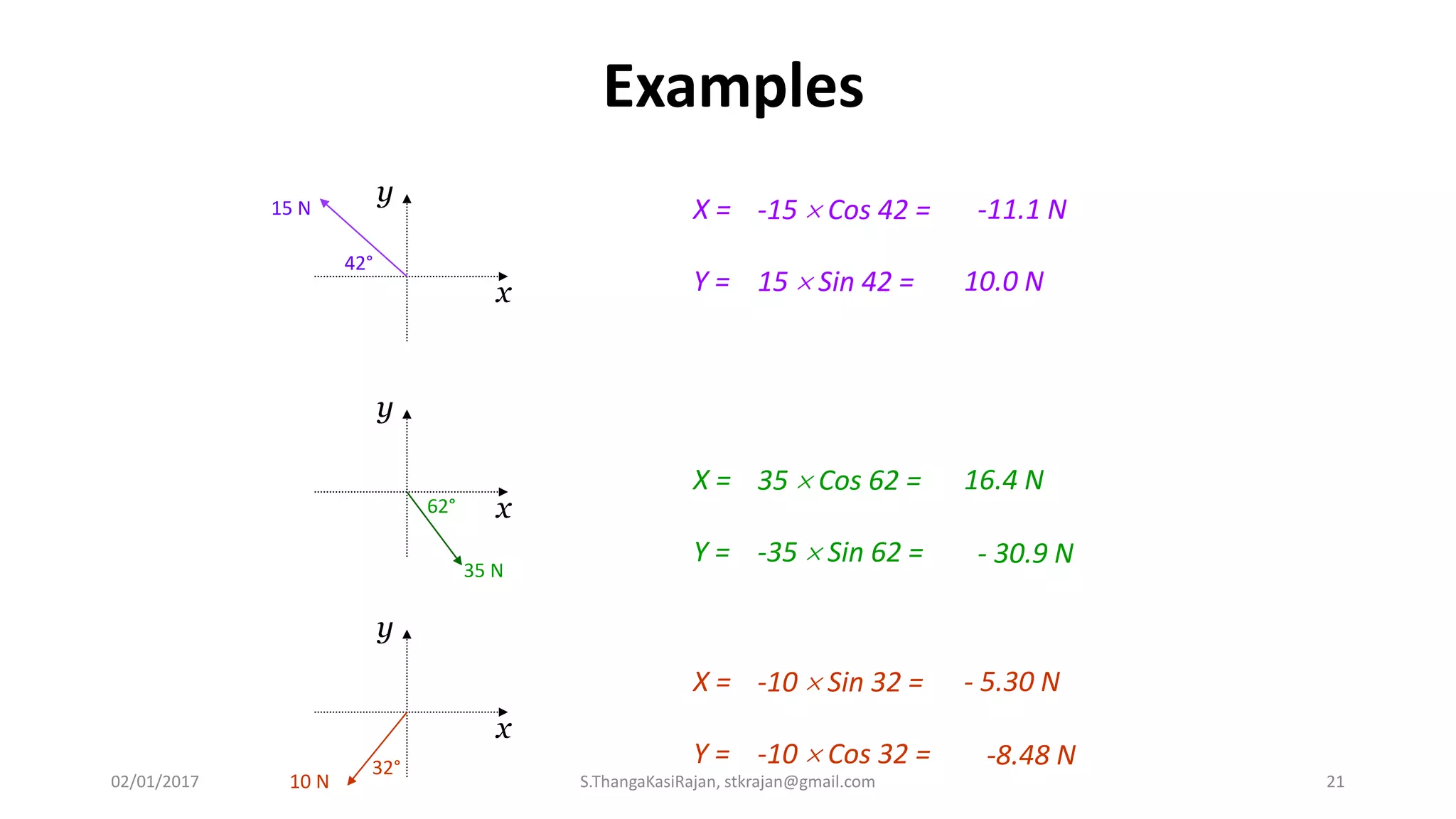
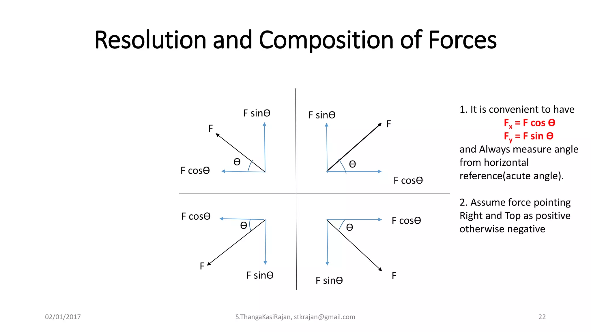
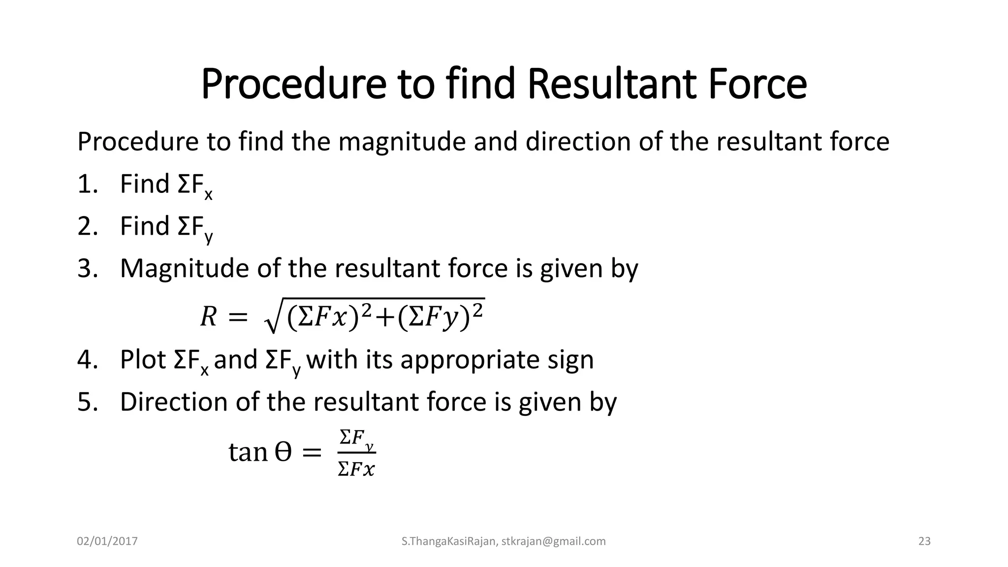
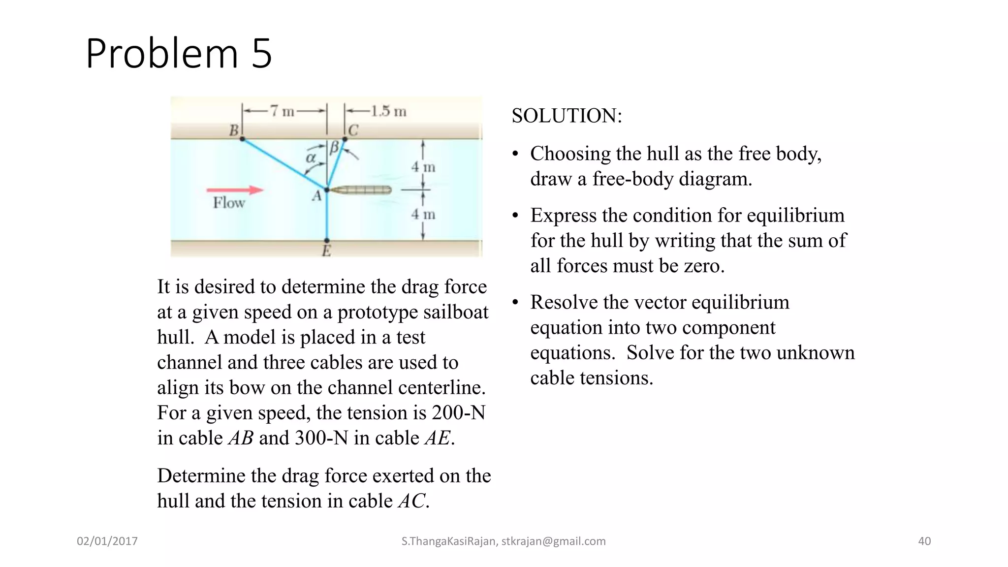
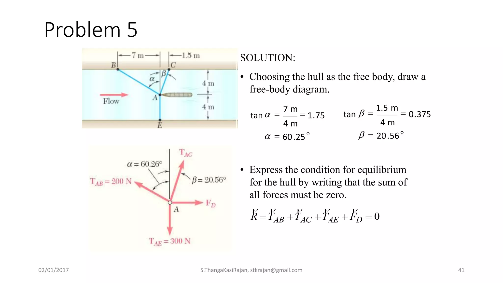
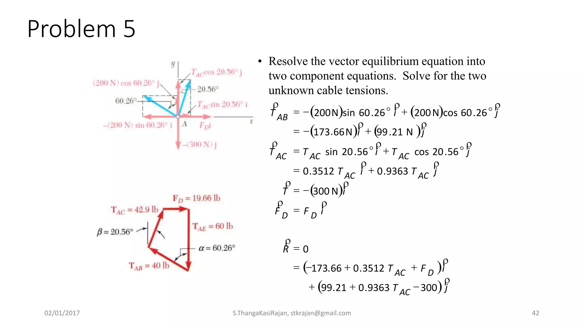
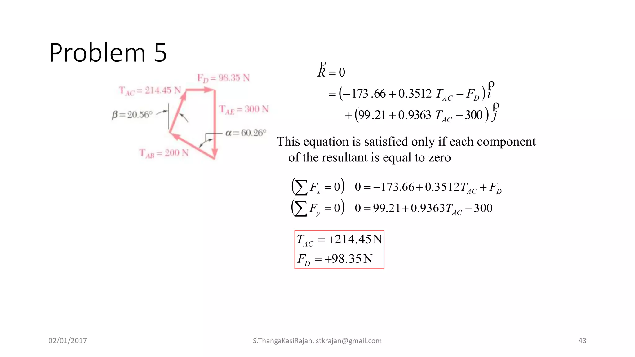

The document provides an overview of engineering mechanics, focusing on the basics of statics and the forces acting on particles and rigid bodies. It outlines the fundamental concepts of mechanics, such as mass, force, and equilibrium, along with key laws including Newton's laws and principles for vector addition. Additionally, it discusses methods for resolving and composing forces through graphical and analytical techniques, and includes problem-solving examples relevant to these concepts.


![Ctm 154[1]](https://cdn.slidesharecdn.com/ss_thumbnails/ctm1541-190506153756-thumbnail.jpg?width=640&height=640&fit=bounds)