Downloaded 1,557 times

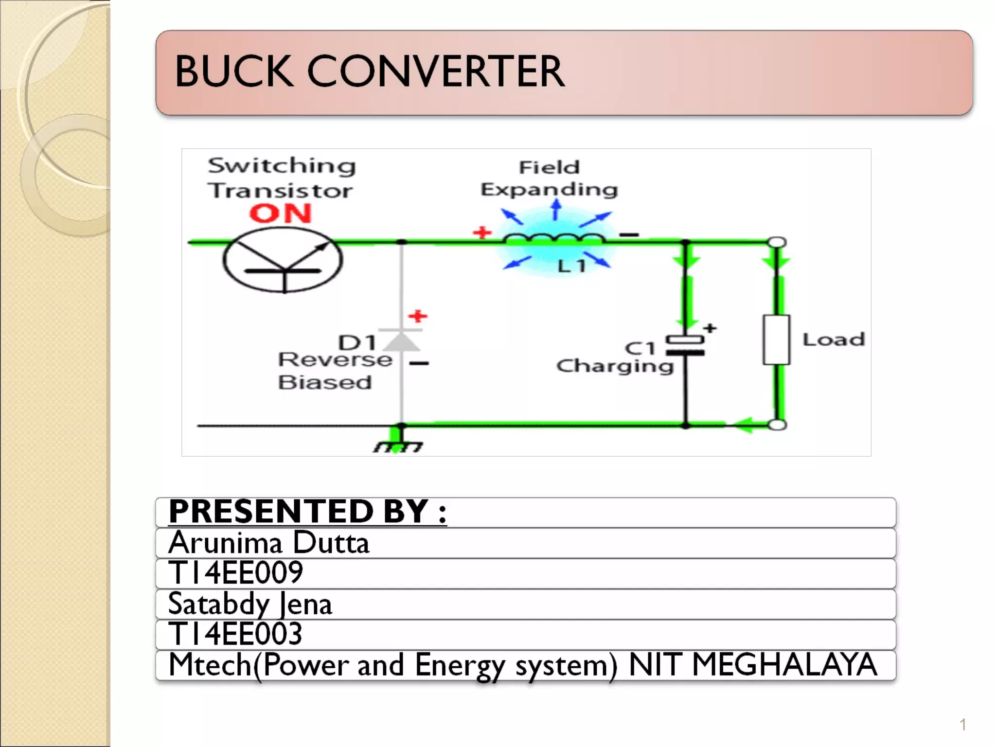
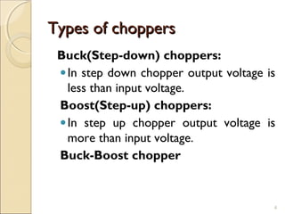
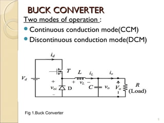
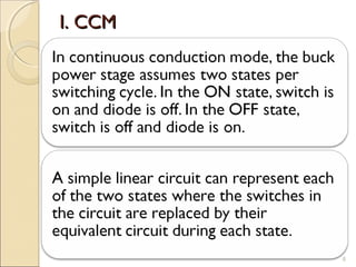
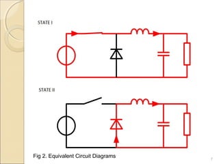
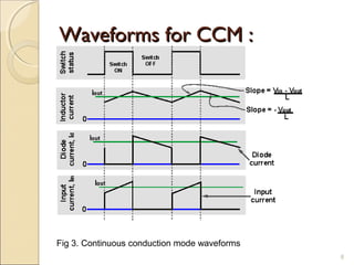
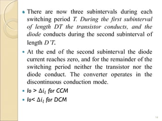
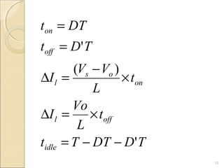
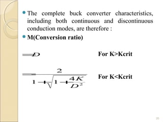


This document discusses buck converters, which are dc-to-dc converters that step down voltage from a constant dc source. It describes two modes of operation for buck converters: continuous conduction mode (CCM) and discontinuous conduction mode (DCM). CCM occurs when inductor current flows continuously, while DCM occurs when inductor current falls to zero for a period during each switching cycle. The document provides equations to calculate operating characteristics like output voltage and efficiency based on component values and switching duty cycle.


![[IJET V2I5P8] Authors: Lakshmi K R, Kavitha Issac, Kiran Boby](https://cdn.slidesharecdn.com/ss_thumbnails/ijet-v2i5p8-161107140749-thumbnail.jpg?width=640&height=640&fit=bounds)