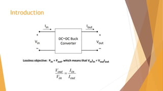
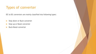
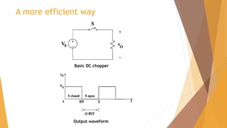
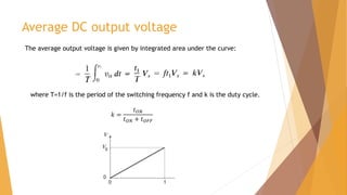
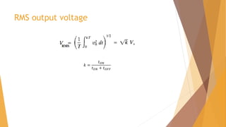
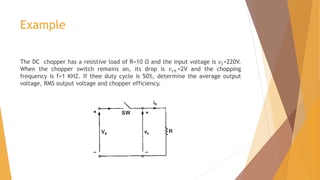
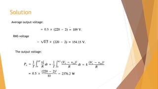
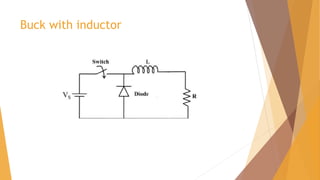
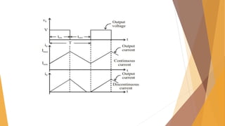
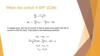
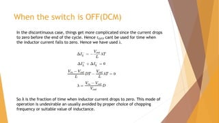
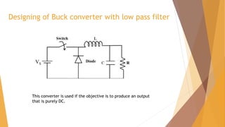
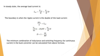
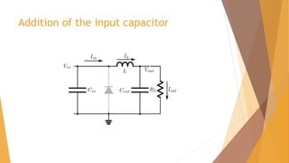
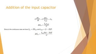
DC-DC converter
Introduction
Types of converter
DC to DC converters are mainly classified into following types:
 Step down or Buck converter
 Step up or Boost converter
 Buck-Boost converter
BUCK CONVERTER
Non-efficient way
A more efficient way
Basic DC chopper
Output waveform
Average DC output voltage
where T=1/f is the period of the switching frequency f and k is the duty cycle.
The average output voltage is given by integrated area under the curve:
𝑘 =
𝑡𝑂𝑁
𝑡𝑂𝑁 + 𝑡𝑂𝐹𝐹
RMS output voltage
𝑘 =
𝑡𝑂𝑁
𝑡𝑂𝑁 + 𝑡𝑂𝐹𝐹
Example
The DC chopper has a resistive load of R=10 Ω and the input voltage is 𝑣𝑠=220V.
When the chopper switch remains on, its drop is 𝑣𝑐ℎ =2V and the chopping
frequency is f=1 KHZ. If thee duty cycle is 50%, determine the average output
voltage, RMS output voltage and chopper efficiency.
Solution
Average output voltage:
RMS voltage
The output voltage:
The input power,
The chopper efficiency
Methods of controlling duty cycle
 Pulse Width Modulation: 𝑡𝑂𝑁 is varied keeping chopping frequency f and
chopping period T constant.
 Variable frequency control: chopping frequency f is varied keeping either 𝑡𝑂𝑁
or 𝑡𝑂𝐹𝐹 constant. This method produces harmonics in the output and for large
𝑡𝑂𝐹𝐹 load current may become discontinuous.
Buck with inductor
When the switch is ON
The current flowing through the inductor rises gradually with slope:
Modes of operation
Load current can be continuous or discontinuous depending on the values of ‘L’
and duty cycle ‘D’.
 For a continuous current operation, load current varies between two limits
𝐼𝑚𝑎𝑥 and 𝐼𝑚𝑖𝑛.
 When current becomes equal to 𝐼𝑚𝑎𝑥 the chopper is turned-off and it is
turned-on when current reduces to 𝐼𝑚𝑖𝑛.
When the switch if OFF (CCM)
In steady state, the rise in current in the on state must match the fall in
current in the off state. That leads to the following condition:
When the switch is OFF(DCM)
In the discontinuous case, things get more complicated since the current drops
to zero before the end of the cycle. Hence 𝑡𝑂𝐹𝐹 cant be used for time when
the inductor current falls to zero. Hence we have used λ.
So λ is the fraction of time when inductor current drops to zero. This mode of
operation is undesirable an usually avoided by proper choice of chopping
frequency or suitable value of inductance.
Designing of Buck converter with low pass filter
This converter is used if the objective is to produce an output
that is purely DC.
Assumptions
 Let the value of capacitance be so large that the output voltage
remains almost constant.
 The output current is constant and equal to Io
Waveform with filter
Continuous mode
Required capacitance in terms of
specified voltage ripple
From the graph in slide 18, the zero crossings (the base vertices of the triangle)
will be at exactly the middle of the on and off states.
The peak of ripple is
The charge, which is the integral of current, is the area of the triangle with
base:
Finding value of inductor to be in
continuous mode
Since from slide 12 the ripple inductor current in the continuous mode,
During continuous mode 𝑉𝑂𝑈𝑇 = 𝐷𝑉𝑖𝑛
The boundary is found when the inductor current drops to zero at exactly the
end of the off state. It is also the case when the ripple current is the double
of the load current.
In steady state, the average load current is:
The boundary is when the ripple current is the double of the load current:
The minimum combination of inductance and switching frequency for continuous
current in the buck converter can be calculated from above formula.
Addition of the input capacitor
 Without the input capacitor, the pulsating current produced by the switching
device would need to be completely supplied by the source.
 This generates an AC signal throughout the lines that increases the conducted
EMI on the board.
 The input capacitor is there to buffer the input current at a constant rate and
supply the requested bursts to the regulator.
 It is easy to see that during the off state, the capacitor is charged with input
current while during the off state it is discharged.
 In steady state, the charge added and removed are equal.
Addition of the input capacitor
Question
 A Chopper circuit is operating at a frequency of 2 kHz on a 460 V supply. If the
load voltage is 350 volts, calculate the conduction period of the thyristor in
each cycle.
References
 http://www.philadelphia.edu.jo/academics/fobeidat/uploads/Power%20Elect
ronic%20Course/8%20DC-DC%20Converters.pdf
 http://www.onmyphd.com/?p=voltage.regulators.buck.step.down.converter
 https://www.academia.edu/33316024/Buck_Converter_Design
 http://www.elg.uottawa.ca/~rhabash/ELG4139LNDCDC2012.pdf
 Power Electronics Handbook by Muhammad H.Rashid

Buck converter

  • 1.
  • 2.
  • 3.
    Types of converter DCto DC converters are mainly classified into following types:  Step down or Buck converter  Step up or Boost converter  Buck-Boost converter
  • 4.
  • 5.
  • 6.
    A more efficientway Basic DC chopper Output waveform
  • 7.
    Average DC outputvoltage where T=1/f is the period of the switching frequency f and k is the duty cycle. The average output voltage is given by integrated area under the curve: 𝑘 = 𝑡𝑂𝑁 𝑡𝑂𝑁 + 𝑡𝑂𝐹𝐹
  • 8.
    RMS output voltage 𝑘= 𝑡𝑂𝑁 𝑡𝑂𝑁 + 𝑡𝑂𝐹𝐹
  • 9.
    Example The DC chopperhas a resistive load of R=10 Ω and the input voltage is 𝑣𝑠=220V. When the chopper switch remains on, its drop is 𝑣𝑐ℎ =2V and the chopping frequency is f=1 KHZ. If thee duty cycle is 50%, determine the average output voltage, RMS output voltage and chopper efficiency.
  • 10.
    Solution Average output voltage: RMSvoltage The output voltage:
  • 11.
    The input power, Thechopper efficiency
  • 12.
    Methods of controllingduty cycle  Pulse Width Modulation: 𝑡𝑂𝑁 is varied keeping chopping frequency f and chopping period T constant.  Variable frequency control: chopping frequency f is varied keeping either 𝑡𝑂𝑁 or 𝑡𝑂𝐹𝐹 constant. This method produces harmonics in the output and for large 𝑡𝑂𝐹𝐹 load current may become discontinuous.
  • 13.
  • 14.
    When the switchis ON The current flowing through the inductor rises gradually with slope:
  • 15.
    Modes of operation Loadcurrent can be continuous or discontinuous depending on the values of ‘L’ and duty cycle ‘D’.  For a continuous current operation, load current varies between two limits 𝐼𝑚𝑎𝑥 and 𝐼𝑚𝑖𝑛.  When current becomes equal to 𝐼𝑚𝑎𝑥 the chopper is turned-off and it is turned-on when current reduces to 𝐼𝑚𝑖𝑛.
  • 17.
    When the switchif OFF (CCM) In steady state, the rise in current in the on state must match the fall in current in the off state. That leads to the following condition:
  • 18.
    When the switchis OFF(DCM) In the discontinuous case, things get more complicated since the current drops to zero before the end of the cycle. Hence 𝑡𝑂𝐹𝐹 cant be used for time when the inductor current falls to zero. Hence we have used λ. So λ is the fraction of time when inductor current drops to zero. This mode of operation is undesirable an usually avoided by proper choice of chopping frequency or suitable value of inductance.
  • 19.
    Designing of Buckconverter with low pass filter This converter is used if the objective is to produce an output that is purely DC.
  • 20.
    Assumptions  Let thevalue of capacitance be so large that the output voltage remains almost constant.  The output current is constant and equal to Io
  • 21.
  • 22.
  • 23.
    Required capacitance interms of specified voltage ripple From the graph in slide 18, the zero crossings (the base vertices of the triangle) will be at exactly the middle of the on and off states. The peak of ripple is The charge, which is the integral of current, is the area of the triangle with base:
  • 24.
    Finding value ofinductor to be in continuous mode Since from slide 12 the ripple inductor current in the continuous mode, During continuous mode 𝑉𝑂𝑈𝑇 = 𝐷𝑉𝑖𝑛 The boundary is found when the inductor current drops to zero at exactly the end of the off state. It is also the case when the ripple current is the double of the load current.
  • 25.
    In steady state,the average load current is: The boundary is when the ripple current is the double of the load current: The minimum combination of inductance and switching frequency for continuous current in the buck converter can be calculated from above formula.
  • 26.
    Addition of theinput capacitor  Without the input capacitor, the pulsating current produced by the switching device would need to be completely supplied by the source.  This generates an AC signal throughout the lines that increases the conducted EMI on the board.  The input capacitor is there to buffer the input current at a constant rate and supply the requested bursts to the regulator.  It is easy to see that during the off state, the capacitor is charged with input current while during the off state it is discharged.  In steady state, the charge added and removed are equal.
  • 27.
    Addition of theinput capacitor
  • 28.
    Addition of theinput capacitor
  • 29.
    Question  A Choppercircuit is operating at a frequency of 2 kHz on a 460 V supply. If the load voltage is 350 volts, calculate the conduction period of the thyristor in each cycle.
  • 30.
    References  http://www.philadelphia.edu.jo/academics/fobeidat/uploads/Power%20Elect ronic%20Course/8%20DC-DC%20Converters.pdf  http://www.onmyphd.com/?p=voltage.regulators.buck.step.down.converter https://www.academia.edu/33316024/Buck_Converter_Design  http://www.elg.uottawa.ca/~rhabash/ELG4139LNDCDC2012.pdf  Power Electronics Handbook by Muhammad H.Rashid