Downloaded 1,383 times

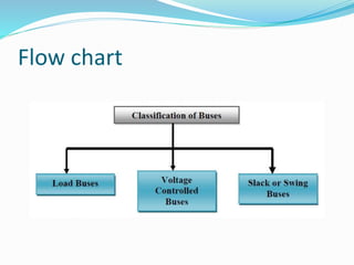
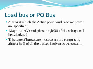
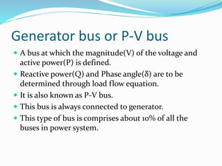
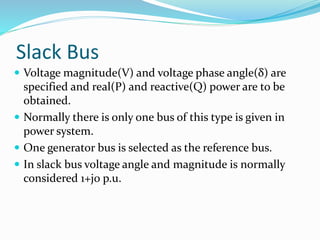
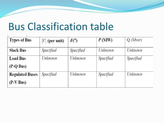
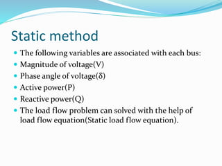
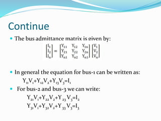
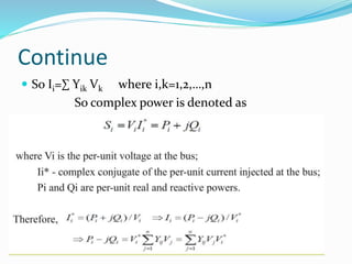
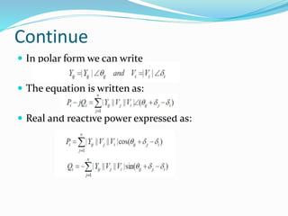
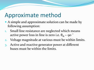
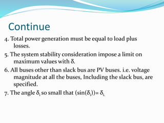
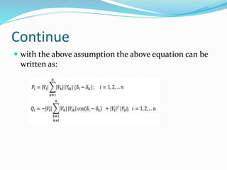


Load flow studies analyze power systems in steady state conditions, determining key parameters such as voltage, current, active, and reactive power. These studies are essential for designing, planning, and optimizing power system operations, with buses classified into load (pq), generator (p-v), and slack types based on specified and determined parameters. The load flow problem can be approached using static equations and bus admittance matrices, with assumptions for simplified calculations.


![[LEC-05] Load Flow Analysis Power System](https://cdn.slidesharecdn.com/ss_thumbnails/lec-05loadflowanalysis-241104145205-494fcb01-thumbnail.jpg?width=640&height=640&fit=bounds)


