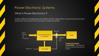
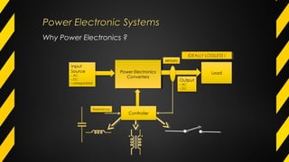
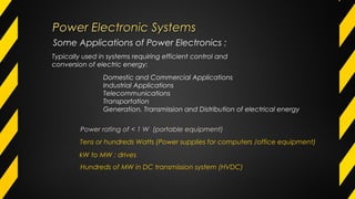
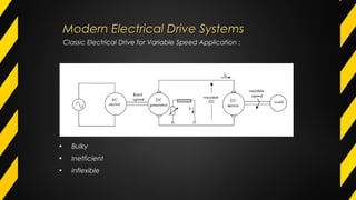
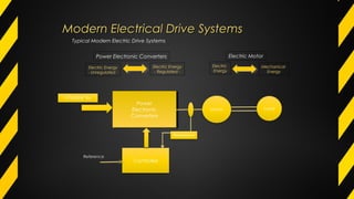
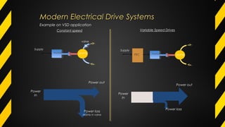
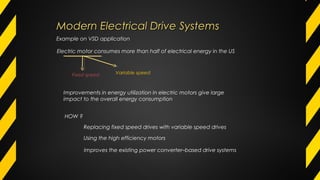
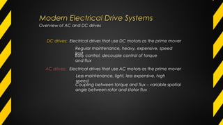
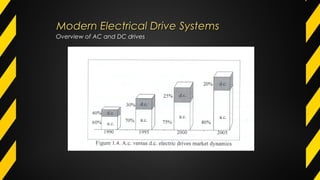
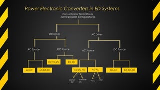
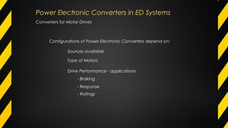
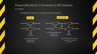
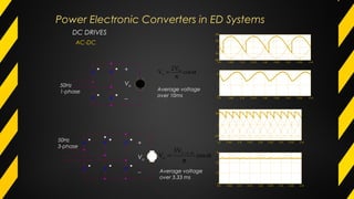
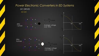
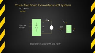
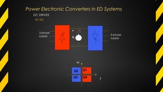
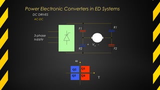
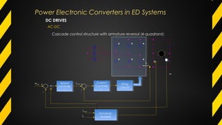
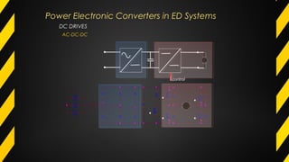
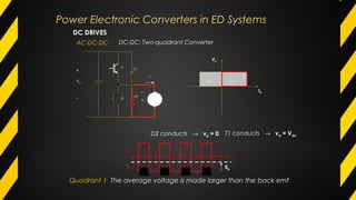
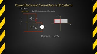
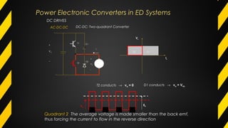
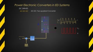
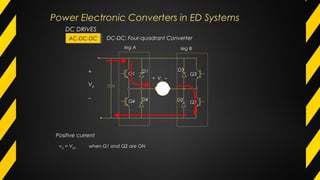
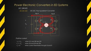
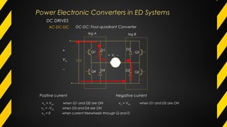
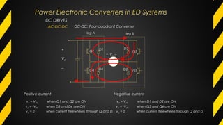
The document discusses power electronic systems and electrical drive systems. It provides an overview of power electronic converters, which are the heart of power electronics systems and are used to efficiently control and convert electric power. Modern electrical drive systems use power electronic converters with electric motors for variable speed applications, providing benefits like improved efficiency over classic fixed speed drives. The document describes different types of power electronic converters that can be used for DC drives and AC drives, including AC-DC, DC-DC, and voltage source converters.
These slides provide an elementary description of Power Electronics and its application domains. It also shows the different power devices and converters.
Applications of power electronics in HVDCKabilesh K
Role of Power electronics in HVDC and Transmission system. What are the components of Power electronics used in HVDC. Types of HVDC Links. Advantages of HVDC over HVAC.
The inverter is a static device. It can convert one form of electrical power into other forms of electrical power. But it cannot generate electrical power. Hence the inverter is a converter, not a generator.
DSTATCOM IS USED IN DISTRIBUTION SYSTEM TO IMPROVE POWER QUALITY LIKE PF CORRECTION,VOLTAGE SAG OR SWELL,HARMONICS ELEMINATION,ETC.VARIOUS CONTROL STRATEGY COMPARISION FOR DSTATCOM.ADVANTAGES AND DISADVANTAGES OF DSTATCOM.APPLICATION OF STASTCOM IN INDIA.
High Voltage Direct Current Transmission SystemNadeem Khilji
The development of HVDC (High Voltage Direct Current) transmission system dates back to the 1930s when mercury arc rectifiers were invented. Since the 1960s, HVDC transmission system is now a mature technology and has played a vital part in both long distance transmission and in the interconnection of systems. Transmitting power at high voltage and in DC form instead of AC is a new technology proven to be economic and simple in operation which is HVDC transmission. HVDC transmission systems, when installed, often form the backbone of an electric power system. They combine high reliability with a long useful life. An HVDC link avoids some of the disadvantages and limitations of AC transmission. HVDC transmission refers to that the AC power generated at a power plant is transformed into DC power before its transmission. At the inverter (receiving side), it is then transformed back into its original AC power and then supplied to each household. Such power transmission method makes it possible to transmit electric power in an economic way.
The world is changing with the a great speed and the speed is fastened with the help of the electronics and the technology created using the electronics.
This is to certify that the research entitled ((Performance of sustainable Mortar using Calcined clay, fly ash, Limestone powder and reinforced with hybrid fiber)) have been conducted at our Technical Engineering College and there is No funding resource for this research from our University.
IEEE REAL TIME PROJECTS FOR POWER ELECTRONICtema_solution
We are Offering the projects in quality and low price with free projects class and demonstration classes. Further Details visit our website TEMASOLUTION.COM
2013 NEW PROJECT TITLES LIST FOR POWER ELECTRONICS TITLEStema_solution
We are Offering the projects in quality and low price with free projects class and demonstration classes. Further Details visit our website TEMASOLUTION.COM
This is to certify that the research entitled ((Performance of sustainable Mortar using Calcined clay, fly ash, Limestone powder and reinforced with hybrid fiber)) have been conducted at our Technical Engineering College and there is No funding resource for this research from our University.
Applications of Smart Grid through Harmonic Current & Reactive Power Compensa...IJMTST Journal
Power factor correction (PFC) is a mandatory functionality of electronic products in the industrial and commercial market in order to mitigate grid harmonics and operate a power system economically. Since the load characteristics of most PFC applications such as home appliances, battery chargers, switched mode power supplies and other digital products support unidirectional power flow, the general ac-dc boost converter with step-up chopper is considered a popular topology. This is because they are low cost, simple, and their performance is well-proven. Its main task inside the system is to maintain dc-link voltage constantly in order to feed loads at different power ratings. In addition, it is necessary to control input current with a pure sinusoidal waveform in phase with input voltage. Active power filters (APF) are another approach capable of improving grid power quality. Many research endeavors have included APFs in their circuit topologies and control strategies. Unlike PFC circuits, the APF is a system in itself which provides compensation of harmonics and reactive power in order to reduce undesirable effects from non-linear loads and uncontrolled passive loads in power systems.
CFD Simulation of By-pass Flow in a HRSG module by R&R Consult.pptxR&R Consult
CFD analysis is incredibly effective at solving mysteries and improving the performance of complex systems!
Here's a great example: At a large natural gas-fired power plant, where they use waste heat to generate steam and energy, they were puzzled that their boiler wasn't producing as much steam as expected.
R&R and Tetra Engineering Group Inc. were asked to solve the issue with reduced steam production.
An inspection had shown that a significant amount of hot flue gas was bypassing the boiler tubes, where the heat was supposed to be transferred.
R&R Consult conducted a CFD analysis, which revealed that 6.3% of the flue gas was bypassing the boiler tubes without transferring heat. The analysis also showed that the flue gas was instead being directed along the sides of the boiler and between the modules that were supposed to capture the heat. This was the cause of the reduced performance.
Based on our results, Tetra Engineering installed covering plates to reduce the bypass flow. This improved the boiler's performance and increased electricity production.
It is always satisfying when we can help solve complex challenges like this. Do your systems also need a check-up or optimization? Give us a call!
Work done in cooperation with James Malloy and David Moelling from Tetra Engineering.
More examples of our work https://www.r-r-consult.dk/en/cases-en/
About
Indigenized remote control interface card suitable for MAFI system CCR equipment. Compatible for IDM8000 CCR. Backplane mounted serial and TCP/Ethernet communication module for CCR remote access. IDM 8000 CCR remote control on serial and TCP protocol.
• Remote control: Parallel or serial interface.
• Compatible with MAFI CCR system.
• Compatible with IDM8000 CCR.
• Compatible with Backplane mount serial communication.
• Compatible with commercial and Defence aviation CCR system.
• Remote control system for accessing CCR and allied system over serial or TCP.
• Indigenized local Support/presence in India.
• Easy in configuration using DIP switches.
Technical Specifications
Indigenized remote control interface card suitable for MAFI system CCR equipment. Compatible for IDM8000 CCR. Backplane mounted serial and TCP/Ethernet communication module for CCR remote access. IDM 8000 CCR remote control on serial and TCP protocol.
Key Features
Indigenized remote control interface card suitable for MAFI system CCR equipment. Compatible for IDM8000 CCR. Backplane mounted serial and TCP/Ethernet communication module for CCR remote access. IDM 8000 CCR remote control on serial and TCP protocol.
• Remote control: Parallel or serial interface
• Compatible with MAFI CCR system
• Copatiable with IDM8000 CCR
• Compatible with Backplane mount serial communication.
• Compatible with commercial and Defence aviation CCR system.
• Remote control system for accessing CCR and allied system over serial or TCP.
• Indigenized local Support/presence in India.
Application
• Remote control: Parallel or serial interface.
• Compatible with MAFI CCR system.
• Compatible with IDM8000 CCR.
• Compatible with Backplane mount serial communication.
• Compatible with commercial and Defence aviation CCR system.
• Remote control system for accessing CCR and allied system over serial or TCP.
• Indigenized local Support/presence in India.
• Easy in configuration using DIP switches.
Hierarchical Digital Twin of a Naval Power SystemKerry Sado
A hierarchical digital twin of a Naval DC power system has been developed and experimentally verified. Similar to other state-of-the-art digital twins, this technology creates a digital replica of the physical system executed in real-time or faster, which can modify hardware controls. However, its advantage stems from distributing computational efforts by utilizing a hierarchical structure composed of lower-level digital twin blocks and a higher-level system digital twin. Each digital twin block is associated with a physical subsystem of the hardware and communicates with a singular system digital twin, which creates a system-level response. By extracting information from each level of the hierarchy, power system controls of the hardware were reconfigured autonomously. This hierarchical digital twin development offers several advantages over other digital twins, particularly in the field of naval power systems. The hierarchical structure allows for greater computational efficiency and scalability while the ability to autonomously reconfigure hardware controls offers increased flexibility and responsiveness. The hierarchical decomposition and models utilized were well aligned with the physical twin, as indicated by the maximum deviations between the developed digital twin hierarchy and the hardware.
Overview of the fundamental roles in Hydropower generation and the components involved in wider Electrical Engineering.
This paper presents the design and construction of hydroelectric dams from the hydrologist’s survey of the valley before construction, all aspects and involved disciplines, fluid dynamics, structural engineering, generation and mains frequency regulation to the very transmission of power through the network in the United Kingdom.
Author: Robbie Edward Sayers
Collaborators and co editors: Charlie Sims and Connor Healey.
(C) 2024 Robbie E. Sayers
Water scarcity is the lack of fresh water resources to meet the standard water demand. There are two type of water scarcity. One is physical. The other is economic water scarcity.
Cosmetic shop management system project report.pdfKamal Acharya
Buying new cosmetic products is difficult. It can even be scary for those who have sensitive skin and are prone to skin trouble. The information needed to alleviate this problem is on the back of each product, but it's thought to interpret those ingredient lists unless you have a background in chemistry.
Instead of buying and hoping for the best, we can use data science to help us predict which products may be good fits for us. It includes various function programs to do the above mentioned tasks.
Data file handling has been effectively used in the program.
The automated cosmetic shop management system should deal with the automation of general workflow and administration process of the shop. The main processes of the system focus on customer's request where the system is able to search the most appropriate products and deliver it to the customers. It should help the employees to quickly identify the list of cosmetic product that have reached the minimum quantity and also keep a track of expired date for each cosmetic product. It should help the employees to find the rack number in which the product is placed.It is also Faster and more efficient way.
3. Power Electronic SystemsPower Electronic Systems
What is Power Electronics ?
A field of Electrical Engineering that deals with the application of power semiconductor
devices for the control and conversion of electric power
Power Electronics
Converters
Power Electronics
Converters
LoadLoad
ControllerController
Output
- AC
- DC
Input
Source
- AC
- DC
- unregulated
Reference
POWER ELECTRONIC
CONVERTERS – the heart of
power a power electronics
system
sensors
4. Why Power Electronics ?
Power Electronics
Converters
Power Electronics
Converters
IDEALLY LOSSLESS !IDEALLY LOSSLESS !
Power Electronic SystemsPower Electronic Systems
5. Why Power Electronics ?
Other factors:
• Improvements in power semiconductors fabrication
• Decline cost in power semiconductor
• Advancement in semiconductor fabrication
• ASICs • FPGA • DSPs
• Faster and cheaper to implement complex
algorithm
• Power Integrated Module (PIM), Intelligent Power
Modules (IPM)
Power Electronic SystemsPower Electronic Systems
6. Some Applications of Power Electronics :
Power rating of < 1 W (portable equipment)
Tens or hundreds Watts (Power supplies for computers /office equipment)
Typically used in systems requiring efficient control and
conversion of electric energy:
Domestic and Commercial Applications
Industrial Applications
Telecommunications
Transportation
Generation, Transmission and Distribution of electrical energy
kW to MW : drives
Hundreds of MW in DC transmission system (HVDC)
Power Electronic SystemsPower Electronic Systems
7. Modern Electrical Drive SystemsModern Electrical Drive Systems
Classic Electrical Drive for Variable Speed Application :
• Bulky
• Inefficient
• inflexible
9. Example on VSD application
Power
In
Power loss
Mainly in valve
Power out
motor pump
valve
Supply
motorPEC pump
Supply
Constant speed Variable Speed Drives
Power
In
Power loss
Power out
Modern Electrical Drive SystemsModern Electrical Drive Systems
10. Electric motor consumes more than half of electrical energy in the US
Fixed speed Variable speed
HOW ?
Improvements in energy utilization in electric motors give large
impact to the overall energy consumption
Replacing fixed speed drives with variable speed drives
Using the high efficiency motors
Improves the existing power converter–based drive systems
Example on VSD application
Modern Electrical Drive SystemsModern Electrical Drive Systems
11. DC drives: Electrical drives that use DC motors as the prime mover
Regular maintenance, heavy, expensive, speed
limit
AC drives: Electrical drives that use AC motors as the prime mover
Less maintenance, light, less expensive, high
speed
Overview of AC and DC drives
Easy control, decouple control of torque
and flux
Coupling between torque and flux – variable spatial
angle between rotor and stator flux
Modern Electrical Drive SystemsModern Electrical Drive Systems
12. Before semiconductor devices were introduced (<1950)
• AC motors for fixed speed applications
• DC motors for variable speed applications
After semiconductor devices were introduced (1960s)
• Variable frequency sources available – AC motors in
variable speed applications
• Coupling between flux and torque control
• Application limited to medium performance
applications – fans, blowers, compressors – scalar
control
• High performance applications dominated by DC motors –
tractions, elevators, servos, etc
Overview of AC and DC drives
Modern Electrical Drive SystemsModern Electrical Drive Systems
13. After vector control drives were introduced (1980s)
• AC motors used in high performance applications – elevators,
tractions, servos
• AC motors favorable than DC motors – however control is complex
hence expensive
• Cost of microprocessor/semiconductors decreasing –predicted 30
years ago AC motors would take over DC motors
Overview of AC and DC drives
Modern Electrical Drive SystemsModern Electrical Drive Systems
14. Overview of AC and DC drives
Modern Electrical Drive SystemsModern Electrical Drive Systems
15. Power Electronic Converters in ED Systems
Converters for Motor Drives
(some possible configurations)
DC Drives AC Drives
DC SourceAC Source AC Source
Const.
DC
Variable
DC
NCC FCC
DC Source
16. Converters for Motor Drives
Configurations of Power Electronic Converters depend on:
Sources available
Type of Motors
Drive Performance - applications
- Braking
- Response
- Ratings
Power Electronic Converters in ED Systems
17. DC DRIVES
Available AC source to control DC motor (brushed)
AC-DC-DCAC-DC-DCAC-DCAC-DC
Controlled Rectifier
Single-phase
Three-phase
Uncontrolled Rectifier
Single-phase
Three-phase
DC-DC Switched mode
1-quadrant, 2-quadrant
4-quadrant
Control Control
Power Electronic Converters in ED Systems
18. DC DRIVES
+
Vo
−
+
Vo
−
α
π
= cos
V2
V m
o
α
π
= −
cos
V3
V m,LL
o
Average voltage
over 10ms
Average voltage
over 3.33 ms
50Hz
1-phase
50Hz
3-phase
AC-DC
Power Electronic Converters in ED Systems
19. DC DRIVES
+
Vo
−
+
Vo
−
α
π
= cos
V2
V m
o
90o
180o
π
mV2
π
− mV2
90o
π
− m,LLV3
π
− − m,LLV3
α
π
= −
cos
V3
V m,LL
o
Average voltage
over 10ms
Average voltage
over 3.33 ms
50Hz
1-phase
50Hz
3-phase
180o
AC-DC
Power Electronic Converters in ED Systems
23. DC DRIVES
AC-DC
Cascade control structure with armature reversal (4-quadrant):
Speed
controlle
r
Speed
controlle
r
Current
Controlle
r
Current
Controlle
r
Firing
Circuit
Firing
Circuit
Armature
reversal
Armature
reversal
iD
iD,ref
iD,ref
iD,
w
wref + +
_
_
Power Electronic Converters in ED Systems
25. T1 conducts → va = Vdc
Q1Q2
Va
Ia
T1
T2
D1
+
Va
-
D2
ia
+
Vdc
−
DC DRIVES
AC-DC-DC DC-DC: Two-quadrant Converter
Power Electronic Converters in ED Systems
26. Q1Q2
Va
Ia
T1
T2
D1
+
Va
-
D2
ia
+
Vdc
−
D2 conducts → va = 0
Va Eb
T1 conducts → va = Vdc
Quadrant 1 The average voltage is made larger than the back emf
DC DRIVES
AC-DC-DC DC-DC: Two-quadrant Converter
Power Electronic Converters in ED Systems
28. Q1Q2
Va
Ia
T1
T2
D1
+
Va
-
D2
ia
+
Vdc
−
T2 conducts → va = 0
Va
Eb
D1 conducts → va = Vdc
Quadrant 2 The average voltage is made smaller than the back emf,
thus forcing the current to flow in the reverse direction
DC DRIVES
AC-DC-DC DC-DC: Two-quadrant Converter
Power Electronic Converters in ED Systems
29. DC DRIVES
AC-DC-DC DC-DC: Two-quadrant Converter
+
vc
2vtri
vc
+
vA
-
Vdc
0
Power Electronic Converters in ED Systems
30. leg A leg B
+ Va −
Q1
Q4
Q3
Q2
D1 D3
D2D4
+
Vdc
−
va = Vdc when Q1 and Q2 are ON
Positive current
DC DRIVES
AC-DC-DCAC-DC-DC DC-DC: Four-quadrant Converter
Power Electronic Converters in ED Systems
31. leg A leg B
+ Va −
Q1
Q4
Q3
Q2
D1 D3
D2D4
+
Vdc
−
va = -Vdc when D3 and D4 are ON
va = Vdc when Q1 and Q2 are ON
va = 0 when current freewheels through Q and D
Positive current
DC DRIVES
AC-DC-DC DC-DC: Four-quadrant Converter
Power Electronic Converters in ED Systems
32. va = -Vdc when D3 and D4 are ON
va = Vdc when Q1 and Q2 are ON
va = 0 when current freewheels through Q and D
Positive current
va = Vdc when D1 and D2 are ON
Negative current
leg A leg B
+ Va −
Q1
Q4
Q3
Q2
D1 D3
D2D4
+
Vdc
−
DC DRIVES
AC-DC-DC DC-DC: Four-quadrant Converter
Power Electronic Converters in ED Systems
33. va = -Vdc when D3 and D4 are ON
va = Vdc when Q1 and Q2 are ON
va = 0 when current freewheels through Q and D
Positive current
va = -Vdc when Q3 and Q4 are ON
va = Vdc when D1 and D2 are ON
va = 0 when current freewheels through Q and D
Negative current
leg A leg B
+ Va −
Q1
Q4
Q3
Q2
D1 D3
D2D4
+
Vdc
−
DC DRIVES
AC-DC-DC DC-DC: Four-quadrant Converter
Power Electronic Converters in ED Systems