Download as PDF, PPTX
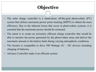
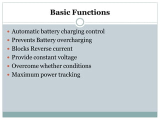
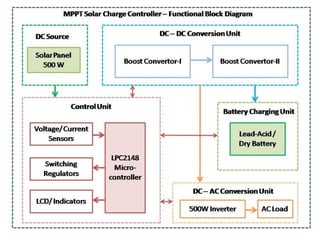


The document presents a solar charge controller utilizing maximum power point tracking (MPPT) technology for enhanced efficiency in off-grid photovoltaic systems. It describes the controller's ability to manage and optimize battery charging for various atmospheric conditions while supporting AC-DC devices of up to 500 watts. The system features include automatic battery control, reverse current blockage, and a microcontroller-based algorithm for maximizing solar energy usage.


