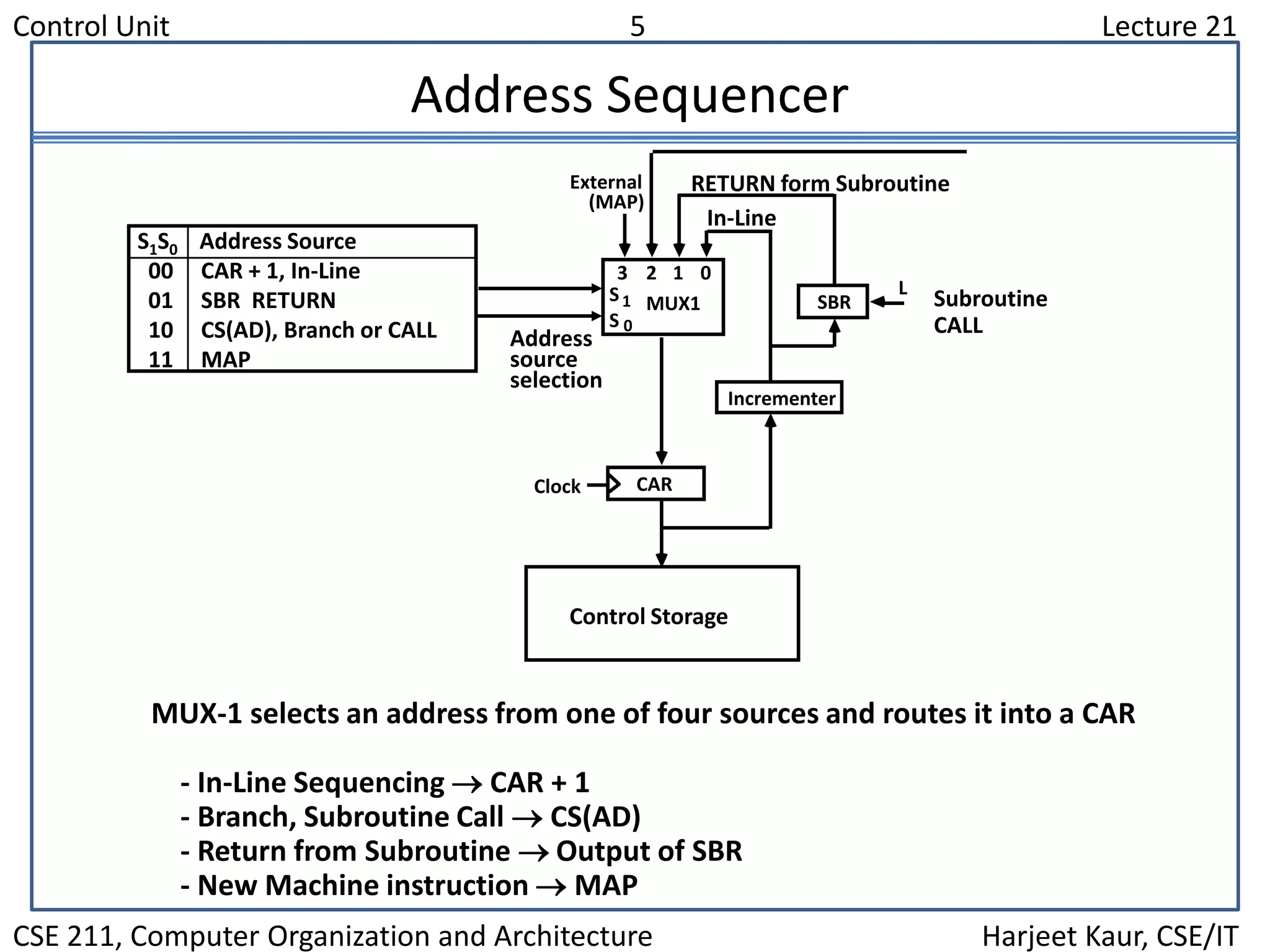
The document discusses the control unit of a computer. It covers control memory, microinstruction sequencing, the microinstruction format, design of the control unit, and the address sequencer. The address sequencer uses a multiplexer to select the next address from various sources like incrementing the current address, returning from a subroutine, branching to a new address, or mapping from the machine instruction.
![Control Unit 3 Lecture 21
CSE 211, Computer Organization and Architecture Harjeet Kaur, CSE/IT
Micro Instruction Format
Microinstruction Format
Symbol OP-code Description
ADD 0000 AC AC + M[EA]
BRANCH 0001 if (AC < 0) then (PC EA)
STORE 0010 M[EA] AC
EXCHANGE 0011 AC M[EA], M[EA] AC
Machine instruction format
I Opcode
15 14 11 10
Address
0
Sample machine instructions
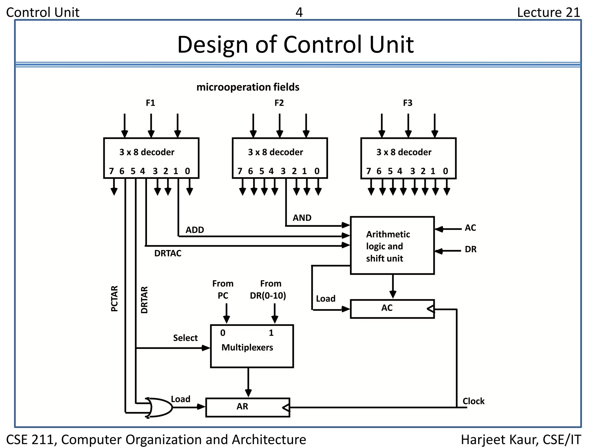
F1 F2 F3 CD BR AD
3 3 3 2 2 7
F1, F2, F3: Microoperation fields
CD: Condition for branching
BR: Branch field
AD: Address field](https://image.slidesharecdn.com/lecture21-130904040505-/75/Lecture-21-3-2048.jpg)


![Vibe Coding vs. Spec-Driven Development [Free Meetup]](https://cdn.slidesharecdn.com/ss_thumbnails/vibecodingvsspecdrivendevelopment-251209105622-43f455e7-thumbnail.jpg?width=640&height=640&fit=bounds)


