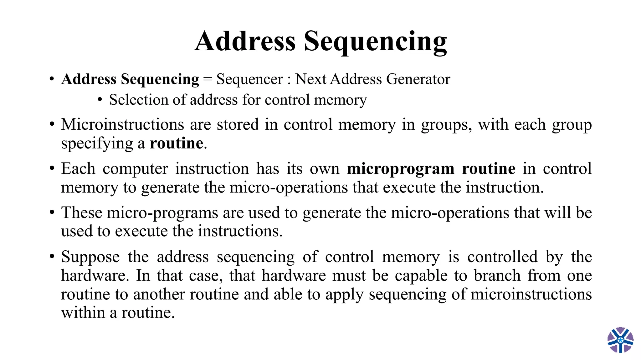
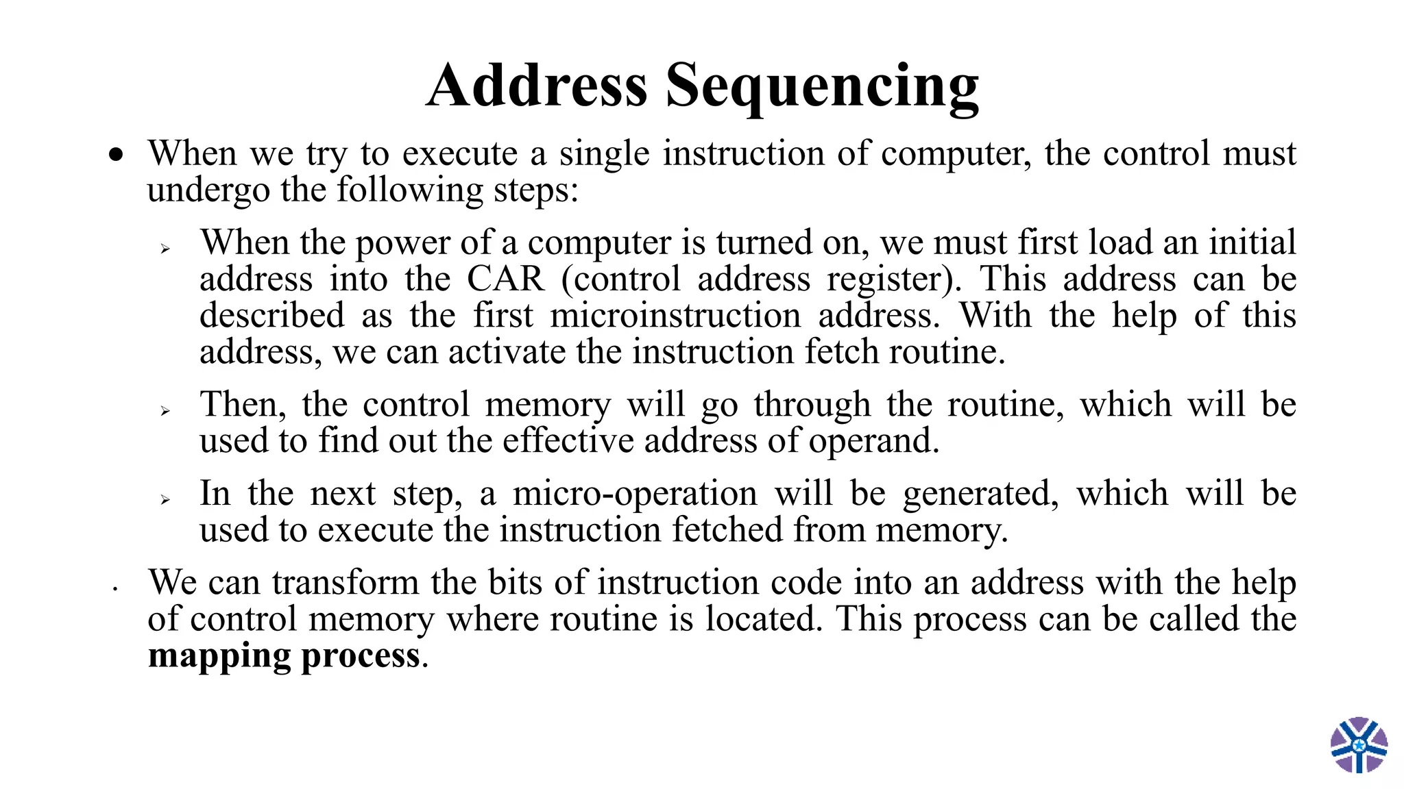
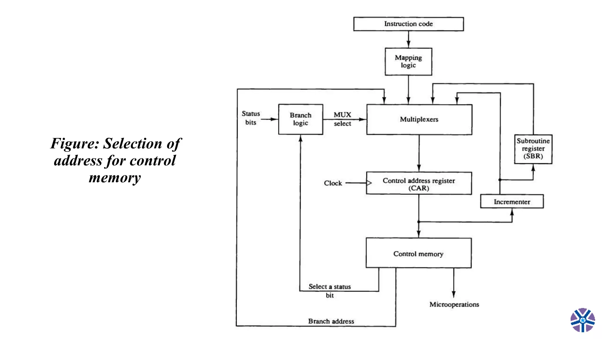
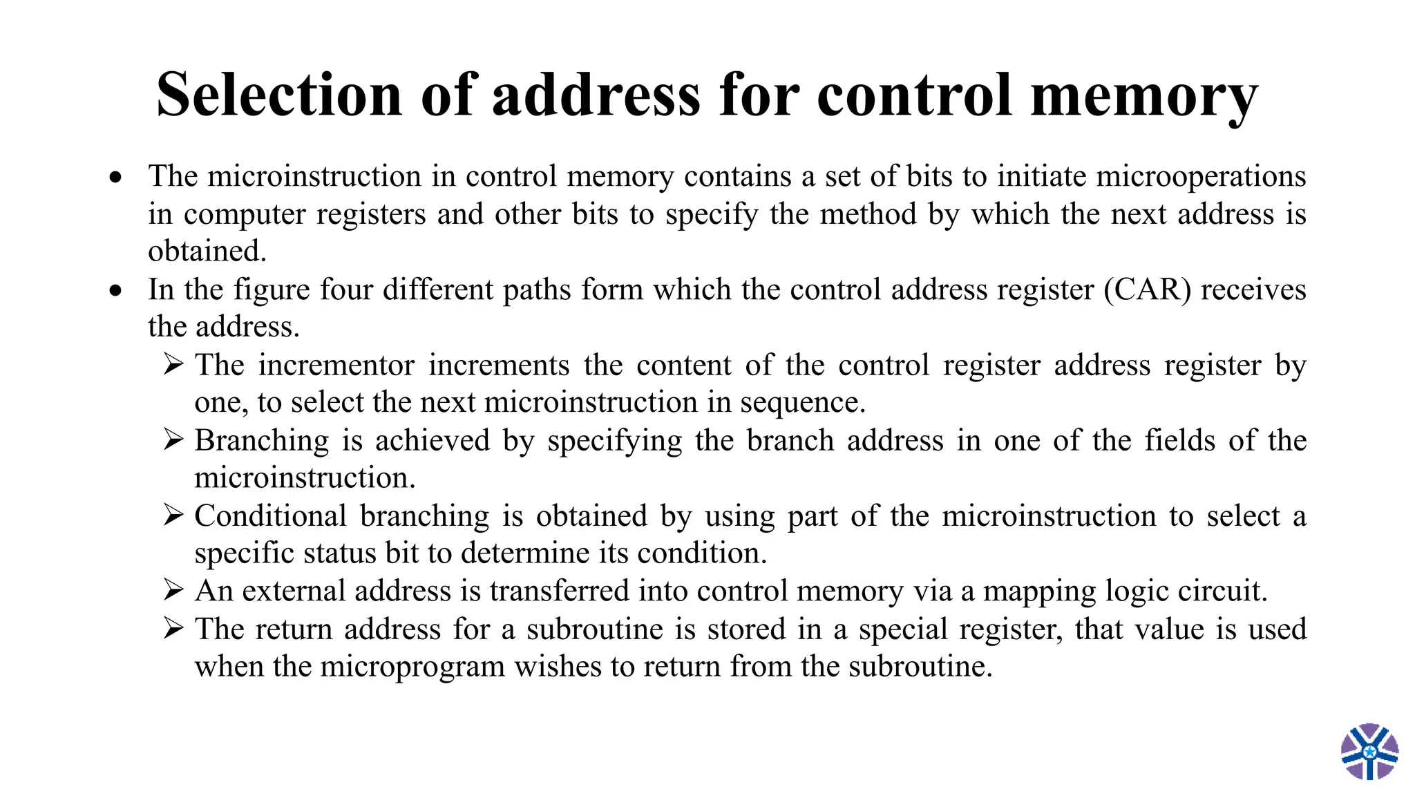
CS304PC:Computer Organization
and Architecture (R18 II(I sem))
Department of computer science and engineering
(AI/ML)
Session 9
by
Asst.Prof.M.Gokilavani
VITS
1/31/2023 Department of CSE (AI/ML) 1
TEXT BOOK:
• 1. Computer System Architecture – M. Moris Mano, Third Edition,
Pearson/PHI.
REFERENCES:
• Computer Organization – Car Hamacher, Zvonks Vranesic, Safea
Zaky, Vth Edition, McGraw Hill.
• Computer Organization and Architecture – William Stallings Sixth
Edition, Pearson/PHI.
• Structured Computer Organization – Andrew S. Tanenbaum, 4th
Edition, PHI/Pearson.
1/31/2023 Department of CSE (AI/ML) 2
Unit II
Microprogrammed Control: Control memory, Address sequencing,
micro program example, Design of Control unit .
Central Processing Unit : General Register Organization, Stack
organization, Instruction formats, Addressing modes, Data Transfer and
Manipulation, Program Control.
1/31/2023 Department of CSE (AI/ML) 3
Topics covered in session 8
1/31/2023 Department of CSE (AI/ML) 4
• Microprogrammed Control
• Control memory
• Address sequencing
• Micro program example
• Design of Control unit
Address Sequencing
• Address Sequencing = Sequencer : Next Address Generator
• Selection of address for control memory
• Microinstructions are stored in control memory in groups, with each group
specifying a routine.
• Each computer instruction has its own microprogram routine in control
memory to generate the micro-operations that execute the instruction.
• These micro-programs are used to generate the micro-operations that will be
used to execute the instructions.
• Suppose the address sequencing of control memory is controlled by the
hardware. In that case, that hardware must be capable to branch from one
routine to another routine and able to apply sequencing of microinstructions
within a routine.
Address Sequencing
 When we try to execute a single instruction of computer, the control must
undergo the following steps:
 When the power of a computer is turned on, we must first load an initial
address into the CAR (control address register). This address can be
described as the first microinstruction address. With the help of this
address, we can activate the instruction fetch routine.
 Then, the control memory will go through the routine, which will be
used to find out the effective address of operand.
 In the next step, a micro-operation will be generated, which will be
used to execute the instruction fetched from memory.
• We can transform the bits of instruction code into an address with the help
of control memory where routine is located. This process can be called the
mapping process.
Address Sequencing
 In brief the address sequencing capabilities required in a control memory
are:
Incrementing of the control address register.
Unconditional branch or conditional branch, depending on status bit
conditions.
A mapping process from the bits of the instruction to an address for
control memory.
A facility for subroutine call and return.
Figure: Selection of
address for control
memory
Selection of address for control memory
 The microinstruction in control memory contains a set of bits to initiate microoperations
in computer registers and other bits to specify the method by which the next address is
obtained.
 In the figure four different paths form which the control address register (CAR) receives
the address.
 The incrementor increments the content of the control register address register by
one, to select the next microinstruction in sequence.
 Branching is achieved by specifying the branch address in one of the fields of the
microinstruction.
 Conditional branching is obtained by using part of the microinstruction to select a
specific status bit to determine its condition.
 An external address is transferred into control memory via a mapping logic circuit.
 The return address for a subroutine is stored in a special register, that value is used
when the microprogram wishes to return from the subroutine.
Conditional Branching
 In the above diagram, the branch logic is used to provide the decision-
making capabilities in the control unit. There are special bits in the system
which is described by the status conditions. These bits are used to provide
the parameter information such as mode bits, the sign bit, carry-out, and
input or output status.
 If these status bits come together with the microinstruction field, they can
control the decision of a conditional branch, which is generated in the
branch logic.
 Here the microinstruction field is going to specify a branch address. The
multiplexer is used to implement the branch logic hardware. If the
condition is met, it will be branch to the initial address. Otherwise, it will
increment the address register.
Conditional Branching
 If we load the branch address into the control address register from
the control memory, we can implement the unconditional branch
microinstruction.
 If the condition is true, it will go to the branch, which is referred to as
the address from the next address field of the current
microinstruction. Otherwise, it will fall through. There are various
types of conditions that need to be tested: Z(zero), C(carry),
O(overflow), N(negative), etc.
Mapping of Instructions
 In the control memory, if the microinstruction specifies a branch to the first
work, in this case, there will be a special type of branch. Here an
instruction contains their micro-program routine. For this special branch,
the status bits will be the bits in the operation code, which is the part of
instruction.
 The above image shows a type of easy mapping process which are going to
convert the 4-bit operation code into the 7-bit address for control memory.
 In the mapping process, the 0 will be placed in the most significant bit of
address. After that, the four operation code bits will be transferred.
Mapping of Instructions
 Lastly, the two least significant bits of CAR will be cleared. With the help
of this process, a micro-program will be provided to each computer
instruction. The micro-program contains the capacity of four
microinstructions.
 If less than four microinstructions are used by the routine, the location of
unused memory can be used for other routines. If more than four
microinstructions are used by the routine, it will use the addresses 1000000
through 1111111.
• This concept can be extended to a more general mapping rule with the help
of PLD (Programmable logic device) or ROM (Read-only memory).
 The above image shows the mapping of address of microinstruction from the
OP-code of an instruction. In the execution program, this microinstruction is
the starting microinstruction.
SUBROUTINE
 Subroutines can be referred to as programs that are used to accomplish a
particular task by the other routines.
 With the help of employing subroutines, we can save the microinstructions.
These subroutines use the common sections of microcode, such as effective
address computation.
 The main routine can get the address for the return with the help of a
subroutine register. In another word, we can say that it becomes a source to
transfer the address to a main routine.
 The register file is used to store the addresses for subroutines. These
register files can be structured in a way that the register will be organized
in the 'Last in first out' (LIFO) stack.
Topics to be covered in next session 9
• Microprogramming Example
1/31/2023 Department of CSE (AI/ML) 18
Thank you!!!

CS304PC:Computer Organization and Architecture Session 8 Address Sequencing.pptx

  • 1.
    CS304PC:Computer Organization and Architecture(R18 II(I sem)) Department of computer science and engineering (AI/ML) Session 9 by Asst.Prof.M.Gokilavani VITS 1/31/2023 Department of CSE (AI/ML) 1
  • 2.
    TEXT BOOK: • 1.Computer System Architecture – M. Moris Mano, Third Edition, Pearson/PHI. REFERENCES: • Computer Organization – Car Hamacher, Zvonks Vranesic, Safea Zaky, Vth Edition, McGraw Hill. • Computer Organization and Architecture – William Stallings Sixth Edition, Pearson/PHI. • Structured Computer Organization – Andrew S. Tanenbaum, 4th Edition, PHI/Pearson. 1/31/2023 Department of CSE (AI/ML) 2
  • 3.
    Unit II Microprogrammed Control:Control memory, Address sequencing, micro program example, Design of Control unit . Central Processing Unit : General Register Organization, Stack organization, Instruction formats, Addressing modes, Data Transfer and Manipulation, Program Control. 1/31/2023 Department of CSE (AI/ML) 3
  • 4.
    Topics covered insession 8 1/31/2023 Department of CSE (AI/ML) 4 • Microprogrammed Control • Control memory • Address sequencing • Micro program example • Design of Control unit
  • 5.
    Address Sequencing • AddressSequencing = Sequencer : Next Address Generator • Selection of address for control memory • Microinstructions are stored in control memory in groups, with each group specifying a routine. • Each computer instruction has its own microprogram routine in control memory to generate the micro-operations that execute the instruction. • These micro-programs are used to generate the micro-operations that will be used to execute the instructions. • Suppose the address sequencing of control memory is controlled by the hardware. In that case, that hardware must be capable to branch from one routine to another routine and able to apply sequencing of microinstructions within a routine.
  • 6.
    Address Sequencing  Whenwe try to execute a single instruction of computer, the control must undergo the following steps:  When the power of a computer is turned on, we must first load an initial address into the CAR (control address register). This address can be described as the first microinstruction address. With the help of this address, we can activate the instruction fetch routine.  Then, the control memory will go through the routine, which will be used to find out the effective address of operand.  In the next step, a micro-operation will be generated, which will be used to execute the instruction fetched from memory. • We can transform the bits of instruction code into an address with the help of control memory where routine is located. This process can be called the mapping process.
  • 7.
    Address Sequencing  Inbrief the address sequencing capabilities required in a control memory are: Incrementing of the control address register. Unconditional branch or conditional branch, depending on status bit conditions. A mapping process from the bits of the instruction to an address for control memory. A facility for subroutine call and return.
  • 8.
    Figure: Selection of addressfor control memory
  • 9.
    Selection of addressfor control memory  The microinstruction in control memory contains a set of bits to initiate microoperations in computer registers and other bits to specify the method by which the next address is obtained.  In the figure four different paths form which the control address register (CAR) receives the address.  The incrementor increments the content of the control register address register by one, to select the next microinstruction in sequence.  Branching is achieved by specifying the branch address in one of the fields of the microinstruction.  Conditional branching is obtained by using part of the microinstruction to select a specific status bit to determine its condition.  An external address is transferred into control memory via a mapping logic circuit.  The return address for a subroutine is stored in a special register, that value is used when the microprogram wishes to return from the subroutine.
  • 10.
    Conditional Branching  Inthe above diagram, the branch logic is used to provide the decision- making capabilities in the control unit. There are special bits in the system which is described by the status conditions. These bits are used to provide the parameter information such as mode bits, the sign bit, carry-out, and input or output status.  If these status bits come together with the microinstruction field, they can control the decision of a conditional branch, which is generated in the branch logic.  Here the microinstruction field is going to specify a branch address. The multiplexer is used to implement the branch logic hardware. If the condition is met, it will be branch to the initial address. Otherwise, it will increment the address register.
  • 11.
    Conditional Branching  Ifwe load the branch address into the control address register from the control memory, we can implement the unconditional branch microinstruction.  If the condition is true, it will go to the branch, which is referred to as the address from the next address field of the current microinstruction. Otherwise, it will fall through. There are various types of conditions that need to be tested: Z(zero), C(carry), O(overflow), N(negative), etc.
  • 12.
  • 13.
    Mapping of Instructions In the control memory, if the microinstruction specifies a branch to the first work, in this case, there will be a special type of branch. Here an instruction contains their micro-program routine. For this special branch, the status bits will be the bits in the operation code, which is the part of instruction.  The above image shows a type of easy mapping process which are going to convert the 4-bit operation code into the 7-bit address for control memory.  In the mapping process, the 0 will be placed in the most significant bit of address. After that, the four operation code bits will be transferred.
  • 14.
    Mapping of Instructions Lastly, the two least significant bits of CAR will be cleared. With the help of this process, a micro-program will be provided to each computer instruction. The micro-program contains the capacity of four microinstructions.  If less than four microinstructions are used by the routine, the location of unused memory can be used for other routines. If more than four microinstructions are used by the routine, it will use the addresses 1000000 through 1111111.
  • 16.
    • This conceptcan be extended to a more general mapping rule with the help of PLD (Programmable logic device) or ROM (Read-only memory).  The above image shows the mapping of address of microinstruction from the OP-code of an instruction. In the execution program, this microinstruction is the starting microinstruction.
  • 17.
    SUBROUTINE  Subroutines canbe referred to as programs that are used to accomplish a particular task by the other routines.  With the help of employing subroutines, we can save the microinstructions. These subroutines use the common sections of microcode, such as effective address computation.  The main routine can get the address for the return with the help of a subroutine register. In another word, we can say that it becomes a source to transfer the address to a main routine.  The register file is used to store the addresses for subroutines. These register files can be structured in a way that the register will be organized in the 'Last in first out' (LIFO) stack.
  • 18.
    Topics to becovered in next session 9 • Microprogramming Example 1/31/2023 Department of CSE (AI/ML) 18 Thank you!!!