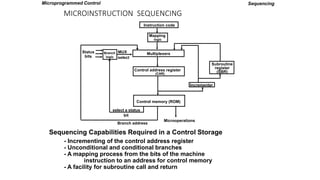
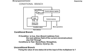
The document discusses microprogrammed control and compares it to hard-wired control implementations. It covers terminology like microprogram, microinstruction, control memory, and sequencing. It explains microinstruction sequencing capabilities like branching. It provides examples of symbolic microprograms and microinstruction formats.


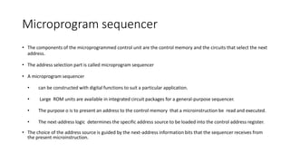
![MACHINE INSTRUCTION FORMAT
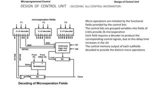
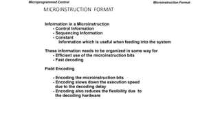
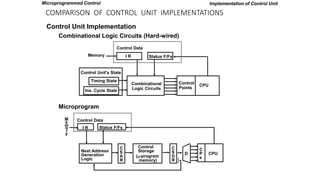
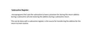
Microinstruction Format for control memory with 20 bits, divided into 4 functional parts , F1,F2,F3 – specify
microoperations, CD – status bit for conditions, BR type of branch, AD branch address 7 bit
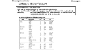
Microprogram
EA is the effective address
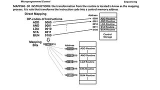
Symbol OP-code Description
ADD 0000 AC AC + M[EA]
BRANCH 0001 if (AC < 0) then (PC EA)
STORE 0010 M[EA] AC
EXCHANGE 0011 AC M[EA], M[EA] AC
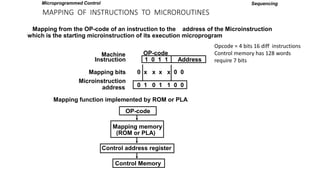
Machine instruction format : one bit for indirect addressing, 4 bits for opcode, 11 bits for address
I Opcode
15 14 11 10
Address
0
Sample machine instructions :
4 sample instructions out of 16 distinct possible instructions
F1 F2 F3 CD BR AD
3 3 3 2 2 7
F1, F2, F3: Microoperation fields
CD: Condition for branching
BR: Branch field
AD: Address field
Microprogrammed Control](https://image.slidesharecdn.com/microprogrammedcontrol-3-221129144221-b3926404/85/MICROPROGRAMMEDCONTROL-3-pptx-12-320.jpg)
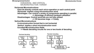
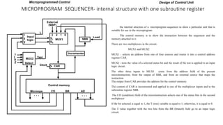
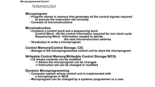
![MICROINSTRUCTION FIELD DESCRIPTIONS - F1,F2,F3
F1 Microoperation Symbol
000 None NOP
001 AC AC + DR ADD
010 AC 0 CLRAC
011 AC AC + 1 INCAC
100 AC DR DRTAC
101 AR DR(0-10) DRTAR
110 AR PC PCTAR
111 M[AR] DR WRITE
Microprogram
F2 Microoperation Symbol
000 None NOP
001 AC AC - DR SUB
010 AC AC DR OR
011 AC AC DR AND
100 DR M[AR] READ
101 DR AC ACTDR
110 DR DR + 1 INCDR
111 DR(0-10) PC PCTDR
F3 Microoperation Symbol
000 None NOP
001 AC AC DR XOR
010 AC AC’ COM
011 AC shl AC SHL
100 AC shr AC SHR
101 PC PC + 1 INCPC
110 PC AR ARTPC
111 Reserved
Microprogrammed Control
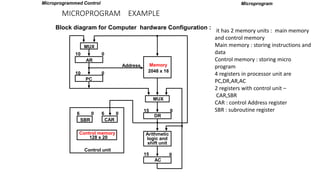
Microoperations are subdivided into 3 fields each 3 bits gives total 21 operations. A micro instruction can choose no
more than 3 operation one from each field. If less than 3 instructions are used then the binary code 000 is used for no
operation for either of the fields.
For example a micro instruction for 9 bits 000 100 101
as follows
DR M[AR] F2=100
PC <- PC + 1 F3=101](https://image.slidesharecdn.com/microprogrammedcontrol-3-221129144221-b3926404/85/MICROPROGRAMMEDCONTROL-3-pptx-13-320.jpg)
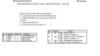
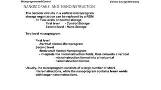
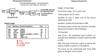
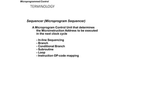
![SYMBOLIC MICROPROGRAM - FETCH ROUTINE
AR PC
DR M[AR], PC PC + 1
AR DR(0-10), CAR(2-5) DR(11-14), CAR(0,1,6) 0
Symbolic microprogram for the fetch cycle:
ORG 64
PCTAR U JMP NEXT
READ, INCPC U JMP NEXT
DRTAR U MAP
FETCH:
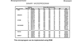
Binary equivalents translated by an assembler
1000000 110 000 000 00 00 1000001
1000001 000 100 101 00 00 1000010
1000010 101 000 000 00 11 0000000
Binary
address F1 F2 F3 CD BR AD
Microprogram
During FETCH, Read an instruction from memory
and decode the instruction and update PC
Sequence of microoperations in the fetch cycle:
Microprogrammed Control](https://image.slidesharecdn.com/microprogrammedcontrol-3-221129144221-b3926404/85/MICROPROGRAMMEDCONTROL-3-pptx-16-320.jpg)